
Spindle speed is one of the most fundamental parameters in plastic CNC machining, and also one of the easiest for beginners to get wrong. Experience from metal machining does not transfer directly to plastics—plastics have poor thermal conductivity and low melting points. A spindle speed that is even slightly too high can turn cutting into melting, and a smeared surface, material sticking to the tool, and dimensional drift can all happen within moments. At the same time, lower speeds are not automatically safer: overly low speeds lead to higher cutting forces, rougher surface finishes, and accelerated tool wear. The right spindle speed for plastic CNC machining must be determined by considering the material type, tool diameter, machining objectives, and machine capabilities together. There is no single number that fits all situations, but there are usable reference ranges and diagnostic principles.
Surface Speed Is More Important Than RPM
Converting Between RPM and Surface Speed
RPM is not an independent parameter. Together with tool diameter, it determines the cutting surface speed—the actual speed at which the tool edge moves relative to the material surface, expressed in meters per minute (m/min). At the same RPM, a larger tool diameter produces a higher surface speed; at the same surface speed, a smaller tool diameter requires a higher RPM.
The conversion formula is: RPM = Surface Speed (m/min) x 1000 / (Pi x Tool Diameter in mm). When switching from a 6 mm tool to a 3 mm tool, the RPM must be doubled to maintain the same surface speed. This also explains why smaller-diameter tools typically need higher spindle speeds—not to cut faster, but to achieve a reasonable surface speed.
Surface Speed Reference Ranges for Plastics
Unlike metal machining, which benefits from well-established cutting data handbooks, surface speed recommendations for plastics are largely built on practical experience. The recommended surface speed range for plastics is lower than that for aluminum but higher than that for steel, with most engineering plastics performing well between 100 and 400 m/min. Heat-sensitive materials should be run at the lower end of this range; materials with good self-lubricating properties can be run at the higher end.
Two scenarios arise outside the recommended range: if the surface speed is too high, frictional heat in the cutting zone cannot be carried away by the chips quickly enough, and the plastic surface temperature exceeds the glass transition temperature or melting point, resulting in melting, discoloration, or material sticking to the tool. If the surface speed is too low, the cutting edge cannot effectively penetrate the material and instead rubs and compresses it, leading to a rough surface, rapid tool wear, and low machining efficiency.
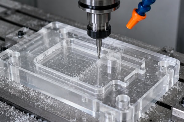
Recommended Spindle Speed Ranges for Common Plastics
The following figures assume a two-flute end mill with diameters of 3 mm and 6 mm, and a moderate depth of cut (axial depth no greater than 50 percent of tool diameter).
Acrylic (PMMA)—Recommended surface speed: 100 to 250 m/min. A 3 mm tool corresponds to approximately 10,000 to 26,000 RPM; a 6 mm tool corresponds to approximately 5,000 to 13,000 RPM. Acrylic is relatively brittle and prone to edge chipping at higher speeds. If compressed-air cooling is used, speeds near the upper end of the range can be adopted.
POM (polyoxymethylene)—Recommended surface speed: 150 to 400 m/min. A 3 mm tool corresponds to approximately 16,000 to 42,000 RPM; a 6 mm tool corresponds to approximately 8,000 to 21,000 RPM. POM is one of the best-machining plastics available, with a wide speed tolerance and stable surface quality even at higher RPM. For finishing small parts, speeds at the upper end can be used.
PC (polycarbonate)—Recommended surface speed: 80 to 200 m/min. A 3 mm tool corresponds to approximately 8,500 to 21,000 RPM; a 6 mm tool corresponds to approximately 4,200 to 10,500 RPM. PC is heat-sensitive; speeds should be kept on the conservative side. Exceeding the recommended range can readily cause stress whitening and edge hazing.
Nylon (PA)—Recommended surface speed: 100 to 250 m/min. A 3 mm tool corresponds to approximately 10,000 to 26,000 RPM; a 6 mm tool corresponds to approximately 5,000 to 13,000 RPM. Nylon is relatively soft and prone to producing stringy chips that wrap around the tool at high speeds. Running at the lower-to-middle portion of the speed range with a larger feed rate helps with chip breaking.
PEEK—Recommended surface speed: 50 to 150 m/min. A 3 mm tool corresponds to approximately 5,300 to 16,000 RPM; a 6 mm tool corresponds to approximately 2,600 to 8,000 RPM. PEEK is hard and generates high cutting forces; tool wear accelerates noticeably at high speeds. Lower speeds combined with smaller depths of cut are recommended.
PTFE—Recommended surface speed: 200 to 500 m/min. A 3 mm tool corresponds to approximately 21,000 to 53,000 RPM; a 6 mm tool corresponds to approximately 10,500 to 26,500 RPM. PTFE is extremely soft and has a very low coefficient of friction; high speeds generally do not cause melting problems, but the effect of material elastic deformation under cutting forces on dimensional accuracy should be taken into account.
Adjusting Speed Based on Tool Diameter
Tool diameter is the variable that most directly affects speed selection. The following are reference RPM values for common tool diameters when machining POM (surface speed taken as 250 m/min):
- 1 mm tool diameter—approximately 79,600 RPM (typically beyond the maximum speed of most spindles; surface speed expectations must be lowered)
- 2 mm tool diameter—approximately 39,800 RPM
- 3 mm tool diameter—approximately 26,500 RPM
- 4 mm tool diameter—approximately 19,900 RPM
- 6 mm tool diameter—approximately 13,300 RPM
- 8 mm tool diameter—approximately 9,900 RPM
- 10 mm tool diameter—approximately 8,000 RPM
For small-diameter tools (1 to 2 mm), the common problem in plastic machining is not insufficient speed; rather, the spindle’s maximum RPM limits the achievable surface speed. For example, a 1 mm tool running at 24,000 RPM—the upper limit of most conventional CNC spindles—delivers a surface speed of only about 75 m/min, well below the ideal range for POM. This means that surface finish with small-diameter tools may not match that achieved with larger tools. As a workaround, the feed rate can be reduced to compensate for the lower surface speed. For large-diameter tools (8 mm and above), the situation is reversed: even at modest RPM, the surface speed can easily exceed the recommended upper limit. In these cases the spindle speed must be actively lowered rather than following commonly quoted ranges. A 10 mm tool at 10,000 RPM already delivers a surface speed of 314 m/min, which is on the high side for most plastics.
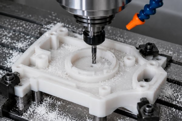
Common Signs of Incorrect Spindle Speed
Spindle speed too high—The plastic surface shows signs of melting, uneven gloss, or darkened color; chips change from uniform flakes to irregular sticky clumps; a coating of melted plastic builds up on the tool; the machining area gives off the odor of overheated plastic; acrylic edges turn white or develop micro-cracks.
Spindle speed too low—Poor surface roughness with pronounced, uneven tool marks; the cutting sound is low and dull, sometimes with a knocking quality; tool wear progresses faster than expected (because cutting forces are higher at low speed); chips are large irregular fragments, and brittle plastics in particular may produce shattered, crumbled chips; small-diameter tools are more likely to break at low speed because the cutting forces exceed what the tool can withstand.
If any of these signs appear during machining, adjusting the spindle speed is one direction to investigate—though not necessarily the only one. Feed rate, depth of cut, and tool condition also influence these outcomes.
Coordinating Spindle Speed with Feed Rate
Spindle speed cannot be discussed in isolation from feed rate. The spindle speed determines how frequently the cutting edge contacts the material; the feed rate determines how much material is removed with each contact. Together they produce the feed per tooth—the distance the tool advances per cutting edge per revolution. In plastic CNC machining, typical feed-per-tooth values range from 0.03 to 0.15 mm, with heat-sensitive materials at the lower end and free-cutting materials at the upper end.
A practical approach: once the spindle speed has been set based on the recommended material range, the feed rate can be calculated from the feed per tooth. The formula is: Feed Rate (mm/min) = RPM x Number of Flutes x Feed per Tooth (mm). Take a 6 mm two-flute end mill machining POM as an example: at 12,000 RPM with a feed per tooth of 0.08 mm, the feed rate = 12,000 x 2 x 0.08 = 1,920 mm/min.
The ratio between spindle speed and feed rate affects surface quality. At a given spindle speed, a higher feed rate means a larger chip load per tooth and more visible tool marks on the surface, but it also means higher efficiency and more heat carried away by the chips. A lower feed rate produces a finer surface, but if the feed is so low that the feed per tooth drops below 0.02 mm, the tool transitions from cutting to rubbing, and the surface actually deteriorates. Finding the balance point between speed and feed requires trial cuts on the actual machine with the specific material and tool.
Frequently Asked Questions
Does running the spindle at maximum speed give the highest productivity?
Not necessarily. Higher spindle speeds do allow higher feed rates and can shorten machining time, but only if the material can handle the additional cutting heat generated at those speeds. For materials such as POM, high speed combined with high feed can deliver both efficiency and surface quality. For PC and acrylic, however, the risk of heat damage at excessive speeds and the resulting rework costs can outweigh the time saved. The prerequisite for maximizing efficiency is first ensuring that machining quality is acceptable.
Do different brands of the same plastic require different spindle speeds?
Sometimes, yes. Even for the same nominal material such as POM or acrylic, different manufacturers may use different formulations, molecular-weight distributions, and additive packages, which can lead to variations in cutting behavior. The most notable example is acrylic—the machining speed for cast sheet and extruded sheet can differ by 20 percent or more. If the material supplier or batch has changed, it is advisable to run a trial cut to confirm whether the existing parameters still apply.
What if the spindle speed is insufficient for small-diameter tools?
Conventional CNC spindle speed limits typically fall between 18,000 and 24,000 RPM, which is indeed on the low side for tools under 2 mm in diameter. Mitigation options include: using a single-flute tool—at the same speed and feed, a single-flute tool delivers double the feed per tooth of a two-flute tool, improving cutting conditions; using a spindle speeder to multiply the spindle output speed by a factor of 3 to 5; or, if the part geometry permits, simply switching to a larger-diameter tool.
Conclusion
There is no single table of spindle speed values that covers every situation in plastic CNC machining. Surface speed is a more meaningful reference metric than RPM itself, and most engineering plastics machine well within a surface speed range of 100 to 400 m/min. For any given part, speed selection must also take tool diameter, feed rate, depth of cut, and cooling conditions into account. In practice, the most reliable method is to start from the material’s recommended surface speed range, convert to a starting RPM using the tool diameter, and then refine through trial cuts—adjusting gradually toward the optimum based on surface finish, chip form, and tool condition. This approach consistently outperforms blindly applying values from any pre-compiled table.
















