Limits, fits and tolerances define the acceptable dimensional variation and assembly relationships between mating mechanical components. Limits establish the maximum and minimum permitted sizes, tolerances define the allowable variation, and fits determine how two parts assemble or move together.
This guide explains limits, fits and tolerances, including their definitions, basic terminology, tolerance types, engineering fits, hole-basis and shaft-basis systems, ISO tolerance charts, and practical calculation examples.
What Are Limits, Fits and Tolerances?
Limits, fits and tolerances are engineering concepts used to control dimensional variation and ensure that manufactured components assemble and function correctly. Limits specify the maximum and minimum permissible dimensions, tolerances define the allowable size variation, and fits describe the resulting relationship between mating parts. Together, they support consistent manufacturing, component interchangeability, and reliable mechanical performance.
Definition of Limits, Fits, and Tolerances
The limits fits and tolerances definition begins with three related but different concepts. A limit defines a permitted dimensional boundary, a tolerance defines the range between allowable boundaries, and a fit describes the relationship between two mating features.
For example, consider a shaft designed with a nominal diameter of 25 mm and acceptable dimensions between 24.980 mm and 24.993 mm. The two values are its size limits, while their difference, 0.013 mm, is the dimensional tolerance.
When the shaft is assembled into a hole, the combined dimensional ranges determine whether the components have clearance, possible interference, or guaranteed interference. This is why fit selection must consider both components rather than a single part.
| Term | Definition | Engineering Example |
| Limit | Maximum or minimum permissible size | 24.980–24.993 mm shaft |
| Tolerance | Difference between upper and lower limits | 0.013 mm |
| Fit | Dimensional relationship between mating parts | Clearance or interference |
| Basic size | Theoretically exact reference dimension | 25.000 mm |
| Actual size | Measured size of the finished feature | 24.987 mm |
Differences Between Limits, Fits, and Tolerances
The main difference is that limits and tolerances describe an individual feature’s permitted dimensions, while fits describe the relationship between mating features. A shaft may satisfy its specified tolerance but still fail to assemble correctly if the corresponding hole does not meet its requirements.
Limits define the acceptable boundaries of size. Tolerance determines the width of that permitted range, and the fit establishes the combined functional result when two manufactured parts are assembled.
A useful way to define limits fits and tolerances is to connect them to the manufacturing workflow: limits guide acceptance, tolerances guide process capability, and fits guide assembly performance. All three must be considered during engineering design.
Why Limits, Fits, and Tolerances Matter in Manufacturing
Limits, fits and tolerances matter because they allow manufacturers to produce interchangeable components while maintaining mechanical function. Without defined dimensional variation, parts from different machines or production batches could require individual adjustment during assembly.
The question of why are tolerances important in manufacturing is closely connected to production efficiency. Appropriate tolerances reduce unnecessary precision requirements while ensuring that functional interfaces, bearing seats, shafts, and locating features operate correctly.
Overly tight tolerances can increase machining time, inspection effort, and rejection rates. Excessively loose tolerances may cause vibration, premature wear, poor alignment, or assembly failure. The goal is to specify the tolerance required by function.
What Are the Basic Terms Used in Limits, Fits and Tolerances?
The basic terms used in limits, fits and tolerances include basic size, nominal size, actual size, upper and lower limits, deviations, allowance, maximum material condition, and least material condition. These terms describe how dimensions are specified, manufactured, measured, and evaluated. Understanding them is necessary before reading tolerance charts or calculating hole-and-shaft fits.
Basic Size, Nominal Size, and Actual Size
Basic size is the theoretically exact dimension from which dimensional limits and deviations are established. In an ISO hole-and-shaft fit designation, both mating components typically share the same basic size.
Nominal size is a convenient size designation used to identify a component or product. In many engineering drawings, the nominal and basic sizes are numerically identical, but the terms are not always interchangeable in every technical context.
Actual size is the measured dimension of the manufactured feature. For example, a shaft specified at a basic size of 25 mm may have an actual measured diameter of 24.989 mm, which must be compared with its permissible limits.
| Dimension Term | Meaning | Example |
| Nominal size | Designated or identified size | 25 mm shaft |
| Basic size | Exact reference for deviations | 25.000 mm |
| Actual size | Measured manufactured dimension | 24.989 mm |
| Upper limit | Maximum acceptable dimension | 24.993 mm |
| Lower limit | Minimum acceptable dimension | 24.980 mm |
Upper and Lower Limits of Size
Upper and lower limits define the permissible dimensional boundaries of a manufactured feature. The upper limit is the largest accepted size, while the lower limit is the smallest accepted size.
For a hole specified between 25.000 mm and 25.021 mm, any diameter outside this range fails the stated size requirement. A measured diameter of 25.012 mm falls within the specified limits.
Limits of size alone do not fully control a feature’s geometry. A hole can satisfy its measured diameter requirement while still having unacceptable roundness, straightness, or position, depending on the drawing requirements and applicable tolerancing standard.
Upper, Lower, and Fundamental Deviations
Upper deviation is the algebraic difference between the maximum permissible size and the basic size. Lower deviation is the corresponding difference between the minimum permissible size and the basic size.
Fundamental deviation establishes the location of a tolerance zone relative to the zero line representing the basic size. In the ISO system, the letter in a tolerance designation identifies this zone position.
For example, an H hole has a zero lower deviation, while an h shaft has a zero upper deviation. A g shaft has a tolerance zone below the basic size, making it suitable for selected clearance fits.
The principal relationships are:
- Upper Deviation = Upper Limit − Basic Size
- Lower Deviation = Lower Limit − Basic Size
- Dimensional Tolerance = Upper Deviation − Lower Deviation
- Dimensional Tolerance = Upper Limit − Lower Limit
For a 25 mm H7 hole with dimensions of 25.000–25.021 mm, the upper deviation is +0.021 mm and the lower deviation is 0 mm. Its total tolerance is 0.021 mm.
Allowance, Maximum Material Condition, and Least Material Condition
Allowance is the intentional dimensional difference between mating parts at their maximum material conditions. For a clearance fit, it corresponds to the minimum clearance, for an interference fit, it represents the maximum interference when expressed as a negative signed difference.
Maximum Material Condition, or MMC, occurs when a feature contains the greatest amount of material within its permitted size limits. For a shaft, this is its largest diameter. For a hole, it is its smallest diameter.
Least Material Condition, or LMC, describes the opposite condition. A shaft reaches LMC at its smallest permissible diameter, while a hole reaches LMC at its largest permissible diameter.
| Feature | Maximum Material Condition | Least Material Condition |
| Shaft | Largest permissible diameter | Smallest permissible diameter |
| Hole | Smallest permissible diameter | Largest permissible diameter |
| External width | Largest permissible width | Smallest permissible width |
| Internal slot | Smallest permissible width | Largest permissible width |
For allowance and tolerance examples, consider a 25 mm H7/g6 fit. The minimum hole diameter is 25.000 mm, and the maximum shaft diameter is 24.993 mm. Their difference gives a minimum clearance, or positive allowance, of 0.007 mm.
What Are the Different Types of Engineering Tolerances?
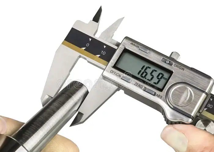
The main types of tolerance in engineering include unilateral tolerance, bilateral tolerance, limit dimensioning, and geometric tolerance. Unilateral and bilateral tolerances control dimensional variation relative to a reference size. Limit dimensions specify the allowable size boundaries directly, while geometric tolerances control characteristics such as form, orientation, location, and runout.
Unilateral Tolerance
Unilateral tolerance permits dimensional variation in only one direction from the specified reference size. The allowed deviation may be positive or negative, depending on the manufacturing and functional requirements.
For example, a hole specified as 25.000 +0.020/0.000 mm can range from 25.000 to 25.020 mm. Its lower limit equals the basic size, while the permitted variation extends in the positive direction.
The unilateral system of tolerance is useful when a feature must not cross a particular size boundary. However, the selected tolerance direction must be based on the intended fit and manufacturing requirements.
Bilateral Tolerance
Bilateral tolerance permits dimensional variation on both sides of a specified reference size. It may be symmetrical, with equal positive and negative deviations, or asymmetrical, with different allowable deviations.
For example, a shaft specified as 25.000 ±0.010 mm has acceptable dimensions from 24.990 to 25.010 mm. The total tolerance is therefore 0.020 mm.
Bilateral tolerances are common for general machining dimensions where variation in both directions is acceptable. However, symmetrical tolerances should not be applied automatically to mating features that require a specific clearance or interference relationship.
| Tolerance Type | Example | Lower Limit | Upper Limit |
| Unilateral positive | 25.000 +0.020/0.000 | 25.000 | 25.020 |
| Unilateral negative | 25.000 +0.000/−0.020 | 24.980 | 25.000 |
| Bilateral symmetrical | 25.000 ±0.010 | 24.990 | 25.010 |
| Bilateral asymmetrical | 25.000 +0.015/−0.005 | 24.995 | 25.015 |
| Limit dimensions | 24.980–25.000 | 24.980 | 25.000 |
Limit Dimensioning and Geometric Tolerances
Limit dimensioning specifies the maximum and minimum permissible dimensions directly rather than relying on plus-and-minus notation. This provides a clear acceptance range for manufacturing and inspection.
Geometric tolerancing controls characteristics that dimensional limits alone may not adequately describe. Depending on the drawing standard, these can include flatness, straightness, perpendicularity, position, circularity, and runout.
For example, a shaft may have an acceptable diameter but excessive runout. In that case, dimensional tolerance alone cannot guarantee the required bearing performance. A separate geometric control may be necessary to ensure functional assembly.
What Are the Three Main Types of Fits?
The three main types of engineering fits are clearance fits, transition fits, and interference fits. Clearance fits provide a gap between mating components, transition fits may produce either a small clearance or interference, and interference fits create a guaranteed dimensional overlap. The correct fit depends on whether the components must move, locate accurately, or remain securely joined.
Engineering fits are particularly important for shafts and holes, but the same principles also apply to certain mating widths, slots, and other features of size.
The three categories are determined by the relative positions of the two tolerance zones. Their labels alone do not specify a complete manufacturing requirement, the basic size and tolerance classes must also be defined.
| Fit Type | Dimensional Relationship | Typical Application |
| Clearance fit | Hole is at least as large as shaft at the limiting condition | Sliding or rotating components |
| Transition fit | Small clearance or interference is possible | Accurate locating assemblies |
| Interference fit | Shaft is always larger than hole | Pressed or shrink-fitted joints |
Clearance Fits: Running, Sliding, and Locational Fits
Clearance fits provide a nonnegative diametral difference between mating parts throughout the specified tolerance ranges. They are used when assembly, disassembly, sliding movement, or rotation requires a gap.
Running fits are used for components that move relative to one another. Depending on the required speed, load, lubrication, and accuracy, these may be described as loose, free, or close running fits.
Sliding and locational clearance fits are commonly selected for guided movement or accurate positioning. A close sliding fit may provide controlled movement, while a looser running fit allows greater freedom but may reduce positioning precision.
The appropriate clearance must account for operating temperature, lubrication, shaft deflection, surface finish, and the intended mechanical function.
Transition Fits: Close Assembly and Accurate Location
Transition fits have overlapping hole and shaft tolerance zones, meaning the assembled components may have either a small clearance or a small interference. The outcome depends on the actual dimensions of the parts.
These fits are useful for accurate location when excessive looseness is undesirable but a heavy permanent press fit is unnecessary. Typical applications include selected locating components, hubs, and precision mechanical assemblies.
A transition fit example is a 25 mm H7/k6 combination. Depending on the actual dimensions, the assembly can range from 0.015 mm interference to 0.019 mm clearance. The final assembly condition cannot be predicted from the nominal size alone.
Interference Fits: Press, Drive, and Force Fits
Interference fits create dimensional overlap because the minimum shaft diameter is greater than the maximum hole diameter. Assembly therefore requires the components to deform elastically, expand or contract thermally, or undergo another suitable controlled joining process.
Press fits are commonly used for bushings, gears, and selected mechanical joints. Drive fits and force fits generally describe progressively more demanding assembly conditions, although the terminology and classification details depend on the applicable standard.
An interference fit example is a 25 mm H7/p6 combination. The specified ranges produce a theoretical diametral interference between 0.001 and 0.035 mm.
The required interference must be checked against material strength, wall thickness, joint geometry, assembly force, operating temperature, and the required holding performance.
How Do Hole-Basis and Shaft-Basis Systems Work?
Hole-basis and shaft-basis systems are standardized methods for selecting mating tolerances. In a hole-basis system, the hole’s lower deviation is zero and different fits are obtained by changing the shaft tolerance zone. In a shaft-basis system, the shaft’s upper deviation is zero and the hole tolerance zone is adjusted to achieve the required fit.
Hole-Basis System
The hole-basis system uses a hole tolerance zone designated by the capital letter H, with its lower deviation positioned at the basic size. Different shaft tolerance zones are then selected to obtain the required fit.
For example, H7/g6 creates a clearance fit, H7/k6 produces a transition fit, and H7/p6 produces an interference fit at suitable basic sizes. The H7 hole specification remains unchanged while the shaft class changes.
Hole-basis systems are frequently preferred because standard drills, reamers, boring tools, and inspection gauges can support standardized hole dimensions. This can simplify manufacturing planning when several shaft configurations share a common hole requirement.
Shaft-Basis System
The shaft-basis system uses a shaft tolerance zone designated by the lowercase letter h, with its upper deviation located at the basic size. The hole tolerance zone changes to provide the desired assembly relationship.
This approach may be useful when a standard shaft diameter must be maintained, such as with certain purchased shafts, stock materials, or components that cannot be economically resized.
For example, a G7/h6 combination can provide a clearance relationship while retaining the shaft’s h6 tolerance class. The hole is adjusted rather than changing the shaft designation.
Differences Between Hole-Basis and Shaft-Basis Systems
The main distinction is the fixed reference feature. Hole-basis designs keep the H hole class constant, while shaft-basis designs keep the h shaft class constant.
Hole-basis systems often simplify manufacturing when holes are produced using standard-size tooling. Shaft-basis systems may be more practical when several mating components must work with one standardized shaft.
| Comparison | Hole-Basis System | Shaft-Basis System |
| Reference component | Hole | Shaft |
| Standard designation | H | h |
| Zero deviation | Hole lower deviation | Shaft upper deviation |
| Variable feature | Shaft | Hole |
| Typical advantage | Standardized hole production | Standardized shaft utilization |
| Example | H7/g6 | G7/h6 |
Neither system is universally more accurate. The preferred approach depends on component availability, machining methods, assembly requirements, and total manufacturing cost.
How Do You Read Limits, Fits and Tolerances Charts?
Limits, fits and tolerances charts are read by identifying the basic dimension, tolerance letter, tolerance grade, and corresponding upper and lower deviations. The letter determines the position of the tolerance zone, while the number identifies its standardized width. The values are then converted into actual dimensional limits to evaluate the intended fit.

ISO 286 provides a widely used system for standardized linear size tolerances and fits. Its tables help engineers specify consistent hole-and-shaft relationships without calculating every deviation independently.
ISO 286-1 establishes the underlying system and terminology, while ISO 286-2 provides tables of standard tolerance classes and limit deviations. These should not be confused with ASME B4.1 fit recommendations without checking the applicable standard.
ISO Tolerance Grades and Fundamental Deviations
ISO tolerance grades define the width of a standardized tolerance zone. A smaller numerical grade generally represents a tighter size tolerance for a given dimension range.
The grades of tolerance commonly encountered in precision machining include IT5, IT6, IT7, IT8, and IT9, although the appropriate grade depends on the feature and manufacturing process.
The fundamental deviation identifies where that tolerance zone lies relative to the basic size. The letter controls position, the grade number controls width. Both are required to determine the complete permissible dimensional range.
| ISO Size Range | IT6 | IT7 | IT8 |
| Over 6 to 10 mm | 9 µm | 15 µm | 22 µm |
| Over 10 to 18 mm | 11 µm | 18 µm | 27 µm |
| Over 18 to 30 mm | 13 µm | 21 µm | 33 µm |
| Over 30 to 50 mm | 16 µm | 25 µm | 39 µm |
| Over 50 to 80 mm | 19 µm | 30 µm | 46 µm |
The values above illustrate standard tolerance widths. The actual maximum and minimum dimensions also depend on the tolerance letter and basic size.
Understanding Hole and Shaft Tolerance Charts
Hole and shaft tolerance charts display permissible deviations for standardized dimensional ranges. Hole designations use capital letters, while shaft designations use lowercase letters.
To read a chart correctly, locate the basic diameter range first. Then identify the required tolerance class and convert the deviations from micrometers to millimeters when necessary.
For example, 21 µm equals 0.021 mm. If a 25 mm H7 hole has deviations of 0 and +21 µm, its permissible diameter is 25.000–25.021 mm.
Quick Reference: Selected ISO 286 Deviations for Basic Sizes Over 18 to 30 mm
| Designation | Feature | Lower Deviation | Upper Deviation |
| H7 | Hole | 0 µm | +21 µm |
| g6 | Shaft | −20 µm | −7 µm |
| h6 | Shaft | −13 µm | 0 µm |
| k6 | Shaft | +2 µm | +15 µm |
| p6 | Shaft | +22 µm | +35 µm |
These values apply to the stated size range and selected tolerance classes. Other diameters or classes must be checked against the corresponding standard tables.
Reading Common Fit Designations Such as H7/g6 and H7/p6
A fit designation combines the basic diameter with the hole and shaft tolerance classes. For example, Ø25 H7/g6 specifies a 25 mm basic diameter, an H7 hole, and a g6 shaft.
The capital H identifies the hole tolerance zone, while the lowercase g identifies the shaft tolerance zone. The numbers 7 and 6 indicate their respective tolerance grades.
At a 25 mm basic diameter, H7/g6 guarantees clearance, while H7/p6 produces interference. H7/k6 represents a transition fit where the actual dimensions determine whether clearance or interference occurs.
| Fit Designation | Hole Limits | Shaft Limits | Fit Type |
| Ø25 H7/g6 | 25.000–25.021 mm | 24.980–24.993 mm | Clearance |
| Ø25 H7/k6 | 25.000–25.021 mm | 25.002–25.015 mm | Transition |
| Ø25 H7/p6 | 25.000–25.021 mm | 25.022–25.035 mm | Interference |
How Do You Calculate Limits, Fits and Tolerances?
Limits, fits and tolerances are calculated by determining the upper and lower permissible dimensions of each mating feature, then comparing the extreme hole and shaft sizes. Subtracting the shaft diameter from the hole diameter gives a signed diametral difference: positive values indicate clearance, while negative values indicate interference.
These calculations allow engineers to evaluate assembly behavior before manufacturing. They are particularly useful when selecting shaft fits, checking purchased components, and verifying drawing requirements.
Formulas for Upper Limits, Lower Limits, and Tolerances
The dimensional limits of a feature are calculated by adding its permitted deviations to the basic size. The total tolerance is the difference between the upper and lower dimensional limits.
The basic formulas are:
- Upper Limit = Basic Size + Upper Deviation
- Lower Limit = Basic Size + Lower Deviation
- Tolerance = Upper Limit − Lower Limit
- Tolerance = Upper Deviation − Lower Deviation
For a limit tolerance example, consider a 25.000 mm dimension with deviations of +0.015 mm and −0.005 mm.
Upper Limit = 25.000 + 0.015 = 25.015 mm
Lower Limit = 25.000 − 0.005 = 24.995 mm
Tolerance = 25.015 − 24.995 = 0.020 mm
The finished feature must fall within the specified limits. A dimension outside this range does not satisfy the stated size tolerance.
Calculating Maximum and Minimum Clearance or Interference
Maximum and minimum clearance are calculated using the extreme sizes of the mating hole and shaft. The same calculation also identifies possible interference when the result becomes negative.
Maximum Clearance = Maximum Hole Size − Minimum Shaft Size
Minimum Clearance = Minimum Hole Size − Maximum Shaft Size
If the minimum clearance is negative, its absolute value represents the maximum possible interference.
For a guaranteed interference fit:
Minimum Interference = Minimum Shaft Size − Maximum Hole Size
Maximum Interference = Maximum Shaft Size − Minimum Hole Size
These are theoretical diametral size differences. They are not equal to assembly force or contact pressure, which require additional material and geometry considerations.
Worked Examples of Hole and Shaft Fits
Typical limits fits and tolerances problems involve calculating the extreme sizes of a hole and shaft to determine their assembly relationship.
The following examples use a common basic diameter of 25 mm. This allows the three fit categories to be compared directly.
Example 1: Clearance Fit — Ø25 H7/g6
Hole Limits = 25.000–25.021 mm
Shaft Limits = 24.980–24.993 mm
Minimum Clearance = 25.000 − 24.993 = 0.007 mm
Maximum Clearance = 25.021 − 24.980 = 0.041 mm
Result: The assembly always has between 0.007 and 0.041 mm of diametral clearance.
Example 2: Transition Fit — Ø25 H7/k6
Hole Limits = 25.000–25.021 mm
Shaft Limits = 25.002–25.015 mm
Maximum Clearance = 25.021 − 25.002 = 0.019 mm
Maximum Interference = 25.015 − 25.000 = 0.015 mm
Result: The assembly may have up to 0.019 mm clearance or up to 0.015 mm interference.
Example 3: Interference Fit — Ø25 H7/p6
Hole Limits = 25.000–25.021 mm
Shaft Limits = 25.022–25.035 mm
Minimum Interference = 25.022 − 25.021 = 0.001 mm
Maximum Interference = 25.035 − 25.000 = 0.035 mm
Result: The assembly always has between 0.001 and 0.035 mm of theoretical diametral interference.
| Fit Type | Minimum Signed Clearance | Maximum Signed Clearance | Result |
| H7/g6 | +0.007 mm | +0.041 mm | Guaranteed clearance |
| H7/k6 | −0.015 mm | +0.019 mm | Clearance or interference |
| H7/p6 | −0.035 mm | −0.001 mm | Guaranteed interference |
Positive values indicate clearance, while negative values indicate interference. The limits describe size combinations, not the resulting assembly force.
For readers searching for solved problems on limits fits and tolerances pdf, these worked calculations demonstrate the method directly. The same formulas can be applied to different basic sizes after obtaining the correct standard deviations.
How Are Limits, Fits and Tolerances Applied in CNC Machining?
Limits, fits and tolerances are applied in CNC machining by defining acceptable feature dimensions, selecting functional assembly fits, controlling manufacturing operations, and verifying finished parts through dimensional inspection. They are especially important for shafts, bearing seats, bushings, locating holes, and other components whose performance depends on accurate mating relationships.

Choosing Fits for Shafts, Bearings, and Bushings
Fit selection begins with the required function of the assembly. Components designed to rotate or slide generally need suitable clearance, while accurately positioned or permanently joined components may require transition or interference fits.
A shaft running inside a plain bushing may require controlled clearance to support lubrication and movement. A pressed bushing installed in a housing may need interference to prevent unwanted rotation or axial movement.
Bearing seats require particular care because the correct fit depends on loading direction, bearing design, operating temperature, and whether the load rotates relative to the bearing ring. Manufacturer recommendations should take priority over generic fit examples.
Key Factors in Fit Selection
Relative Motion: Determine whether the components must rotate, slide, or remain stationary.
Mechanical Load: Consider torque, radial forces, axial forces, and vibration.
Operating Temperature: Evaluate thermal expansion of both mating materials.
Assembly Method: Consider hand assembly, controlled pressing, or thermal assembly.
Service Requirements: Account for lubrication, wear, maintenance, and disassembly.
Specifying Functional Tolerances on Engineering Drawings
Functional tolerances should be specified according to assembly requirements rather than applying the tightest possible values to every dimension. The drawing should identify the basic size, tolerance designation, applicable standard, and critical geometric requirements.
For designers asking how to give tolerance on a drawing, a clear approach is to use standard ISO fit designations when appropriate or specify explicit upper and lower deviations. Dimensions that are not functionally critical can often use suitable general tolerances.
For example, a precision shaft may require an IT6 diameter tolerance, while a noncritical external length may allow substantially greater variation. Separating critical and noncritical dimensions improves manufacturing efficiency and prevents unnecessary cost.
Engineering drawings should also define relevant datums, surface finish, roundness, position, or runout requirements when these affect function. A correct diameter alone does not guarantee that mating components will assemble properly.
Measuring and Inspecting CNC-Machined Parts
Dimensional inspection confirms that finished CNC-machined components meet their specified size limits and geometric requirements. The inspection method depends on feature type, tolerance magnitude, material, and production volume.
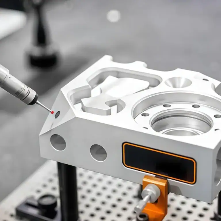
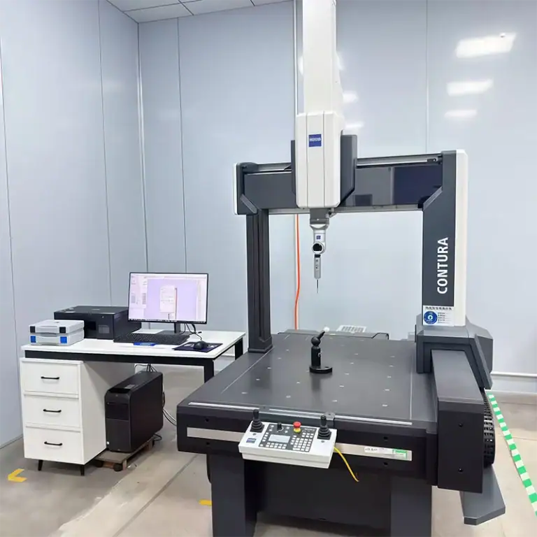
Micrometers are commonly used for precision shaft diameters, while bore gauges, calibrated plug gauges, and coordinate measuring machines can support hole inspection. High-volume production may use dedicated functional gauges or specialized measurement systems.
Temperature, part cleanliness, measuring force, calibration, and operator technique all influence measurement reliability. For tight fits, inspection uncertainty should be small enough to support meaningful acceptance decisions.
| Feature | Typical Inspection Method | Main Verification Purpose |
| Shaft diameter | Outside micrometer | Size limits |
| Hole diameter | Bore gauge or calibrated plug gauge | Internal dimensions |
| Hole position | CMM or suitable positional measurement | Assembly alignment |
| Shaft runout | Dial indicator or roundness equipment | Rotational accuracy |
| Flat mating surface | Surface plate or CMM | Flatness and contact |
| Production fit | Functional GO/NO-GO gauge | Limit verification |
A reliable CNC machining process combines controlled cutting with appropriate inspection. For critical assembly features, first-article measurement and ongoing process monitoring can help identify variation before large quantities of parts are produced.
FAQs
How Do You Calculate Minimum And Maximum Clearance Between A Hole And Shaft?
Minimum clearance is calculated by subtracting the largest permissible shaft diameter from the smallest permissible hole diameter. Maximum clearance is the largest hole diameter minus the smallest shaft diameter. For a 25 mm H7/g6 fit, the hole measures 25.000–25.021 mm and the shaft measures 24.980–24.993 mm. The minimum clearance is 0.007 mm, while the maximum is 0.041 mm. These are diametral values. Actual operating clearance also depends on temperature, geometry, and assembly conditions.
What Is The Difference Between Hole-Basis And Shaft-Basis Fit Systems?
The hole-basis system keeps the H hole tolerance class as the reference and changes the shaft tolerance class to obtain different fits. The shaft-basis system keeps the h shaft class as the reference and changes the hole tolerance class. Hole-basis systems are common because standardized hole machining can simplify production. Shaft-basis systems may be useful when working with standardized shaft stock or purchased components. The best approach depends on tooling availability, component design, assembly requirements, and manufacturing cost.
How Do You Read ISO Fit Designations Such As H7/g6?
An ISO fit designation identifies the basic dimension and tolerance classes of mating features. In Ø25 H7/g6, 25 mm is the basic diameter, H7 specifies the hole tolerance class, and g6 specifies the shaft tolerance class. Capital letters identify holes, while lowercase letters identify shafts. At 25 mm, H7 allows 25.000–25.021 mm and g6 allows 24.980–24.993 mm. This produces a clearance fit. Always check the appropriate ISO 286 tables because permissible deviations depend on the basic size range.
How Does Temperature Affect Clearance And Interference Fits?
Temperature changes fit dimensions because mating components expand or contract according to their thermal expansion coefficients. For example, aluminum expands approximately 23 × 10⁻⁶/K, while typical steel expands around 12 × 10⁻⁶/K. For a 25 mm aluminum housing with a steel shaft, a uniform 40°C temperature rise could increase diametral clearance by approximately 0.011 mm in a simple unconstrained model. Actual behavior depends on geometry, mechanical constraints, temperature gradients, and material properties. Thermal effects must therefore be considered in precision assemblies.
How Can You Verify That CNC-Machined Parts Meet The Required Fit Tolerances?
Verification requires measuring the mating features and comparing their actual dimensions with the specified tolerance limits. Shafts can be checked using calibrated micrometers, while holes may require bore gauges, plug gauges, or coordinate measuring equipment. For a 25 mm H7/g6 fit, both the hole and shaft must satisfy their individual permitted ranges. Critical assemblies may also require roundness, position, and runout inspection. Reliable verification depends on calibrated equipment, controlled measurement conditions, suitable inspection uncertainty, and documented results.
Conclusion
Limits, fits and tolerances establish the dimensional relationships that allow mechanical components to assemble, move, and operate reliably. Understanding size limits, deviations, tolerance grades, and the three major fit types helps engineers select appropriate hole-and-shaft combinations.
At TiRapid, we provide precision CNC machining and manufacturing services for custom metal and plastic components. Our team supports CNC milling, turning, tolerance evaluation, DFM analysis, and dimensional inspection to help customers achieve accurate features, reliable fits, and consistent component quality.