Smart manufacturing is driving the development of industrial robots, collaborative robots, vision inspection systems, and automated production lines. Robot components must provide accurate dimensions, stable structures, and compatibility with rapid changeovers, continuous operation, and complex workstation assembly. Components such as sensor brackets, vision module mounts, robot connectors, guide components, and precision fixtures often feature multiple holes, irregular contours, and strict positioning requirements. CNC machining uses digital control to perform precision milling, turning, drilling, and threading according to engineering drawings, providing reliable components for smart manufacturing equipment.
Key Advantages of CNC Machining for Smart Manufacturing Robot Components
Smart manufacturing equipment relies on different robot components working together. Machining accuracy directly affects assembly, positioning, and operational performance. CNC machining uses programmed tool movements to produce complex structures according to design specifications. Standardized manufacturing processes also help improve consistency, making CNC machining suitable for customized development and repeat batch production.
High-Precision Machining Improves Robot Component Positioning
Vision inspection robots, automated assembly robots, and precision handling systems often require mounting points for sensors, cameras, linear guides, and actuators. Hole spacing, mounting-surface flatness, and positioning references must meet design requirements. Otherwise, deviations may affect inspection positions, gripping accuracy, or equipment stability.
CNC machining controls critical dimensions according to engineering drawings. Finishing operations, dedicated fixtures, and dimensional inspection help improve manufacturing consistency. For example, a vision camera bracket must maintain a stable mounting position, a guide block must meet hole-position and fit requirements, and a robot connector plate must align with the specified assembly reference. Appropriate machining processes help reduce rework and improve overall assembly efficiency.
Customized Machining Supports Rapid Production Line Changeovers
Smart manufacturing lines frequently require changes to fixtures, positioning mechanisms, and robot end tools when switching between product models. Standard components may not meet every workstation’s structural requirements. Customized CNC machining can produce dedicated components based on equipment layout, available installation space, and functional needs.
For small-batch development projects, modifying a CNC program can adjust hole positions, contours, and dimensions without requiring a new mold. For established products, validated programs and inspection standards support repeat production and consistent dimensions across batches. Manufacturers should select suitable machining methods based on component complexity, order quantity, and delivery schedules.
Multiple Materials and Machining Processes Meet Different Equipment Requirements
Material selection for robot components depends on weight, stiffness, wear resistance, corrosion resistance, and the working environment. Different materials suit different equipment structures, and CNC machining parameters can be adjusted to match material characteristics.
Aluminum alloy components: Suitable for lightweight mounting bases, camera brackets, connector plates, and equipment housings. Aluminum alloys offer relatively low weight and good machinability.
- Stainless steel components: Suitable for interface parts, sensor mounts, and industrial fixture components that require corrosion resistance or higher structural strength.
- Alloy steel components: Suitable for transmission connectors and mechanical positioning parts exposed to higher loads or demanding wear conditions.
- Engineering plastic components: Can be used for certain insulating supports, light-duty guide components, and non-metallic parts for specialized environments. Material selection should account for temperature, loading, and wear requirements.
Matching materials to the component’s loading conditions and installation environment, then selecting appropriate machining and finishing processes, helps balance manufacturing efficiency, service performance, and product life.
CNC Machining Methods and Applications for Smart Manufacturing Robot Components
Smart manufacturing robot components are used in vision inspection, automated assembly, material handling, precision positioning, and workstation changeovers. Since component geometries vary, manufacturing plans should consider engineering drawings, tolerances, assembly references, and production quantities. This helps ensure accurate integration with sensors, drive mechanisms, and other equipment modules.
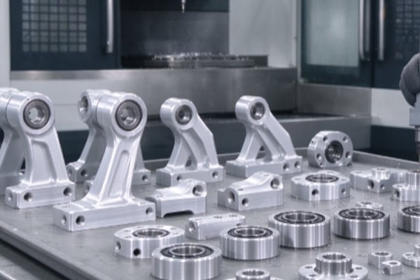
CNC Machining Workflow for Smart Manufacturing Robot Components
A well-defined machining workflow helps reduce programming errors, dimensional deviations, and assembly problems. For components with complex hole patterns, mounting interfaces, and irregular contours, critical dimensions and positioning references should be confirmed before machining. Roughing and finishing operations should then be arranged according to the actual geometry.
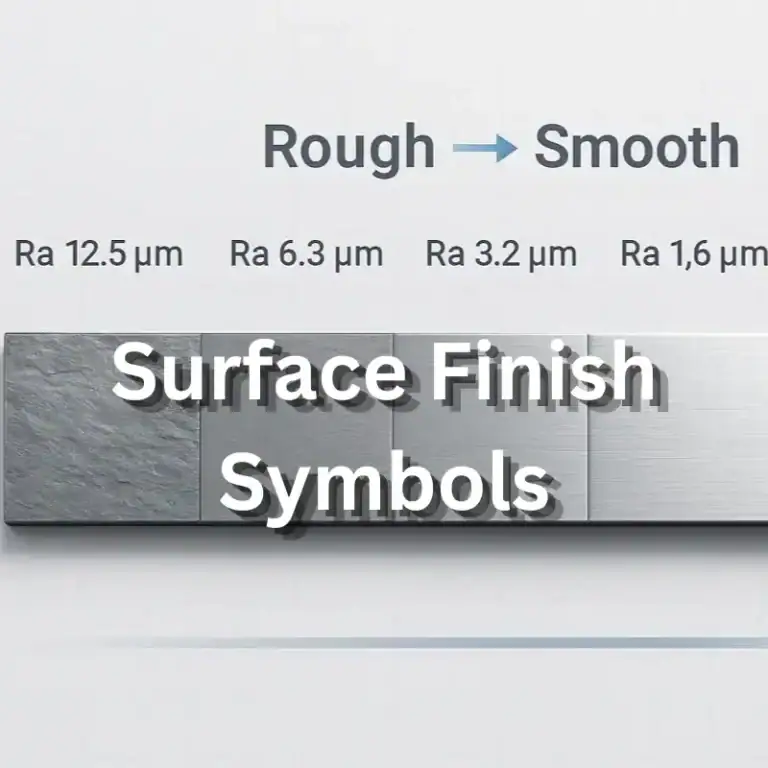
- Drawing and technical requirement review: Verify 3D models, dimensional tolerances, hole positions, thread specifications, surface roughness, and material requirements. Identify critical inspection items.
- Material and blank preparation: Select suitable materials and blanks according to component dimensions, structural strength, and machining allowances. Confirm that the material condition meets production requirements.
- Fixture and program design: Determine the clamping method, tool paths, machining references, and operation sequence to reduce errors caused by repeated positioning.
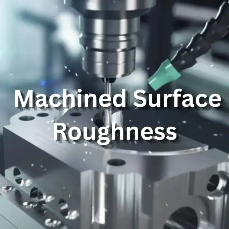
- CNC cutting operations: Perform milling, turning, drilling, boring, tapping, and any required finishing operations according to the component geometry.
- Deburring and surface treatment: Remove burrs around holes and edges. Apply anodizing, passivation, or other suitable treatments according to customer requirements.
- Dimensional inspection and delivery: Check critical dimensions, hole positions, appearance, and surface quality. Complete packaging and delivery after confirming compliance with the drawings.
For components with complex structures, a comprehensive first-article inspection can identify issues before batch production. Tool offsets and process parameters can then be adjusted based on measurement results. During production, manufacturers should monitor tool wear, machine condition, and material variations to maintain consistent quality.
Machining Applications for Vision Inspection and Intelligent Sensing Components
Intelligent vision systems use industrial cameras, sensors, and lighting modules to identify product positions, dimensions, and surface conditions. Camera mounts, lens holders, sensor brackets, and inspection equipment connector plates require stable mounting structures to prevent assembly deviations from affecting the working position of the vision system.
CNC machining can produce vision components with precision mounting holes, adjustment slots, and positioning surfaces for different camera specifications and equipment layouts. For inspection stations that require frequent adjustments, designers can incorporate standardized interfaces and adjustable structures to simplify installation, maintenance, and product changeovers.
During machining, manufacturers should pay close attention to mounting-surface flatness, hole relationships, and connection dimensions. Surface treatments should be selected according to the design and operating environment.
2.3 Components for Automated Assembly, Material Handling, and Modular Workstations
Automated assembly robots use fixtures, locating blocks, guide components, and connector bases to grip, move, and assemble workpieces. Material handling systems require stable mounting components to connect end effectors, sensors, and drive mechanisms. In modular production lines, components must also support quick installation and removal, along with interface compatibility between different workstations.
CNC machining is suitable for components with complex slots, mounting holes, locating steps, and non-standard interfaces. Designs should allow sufficient assembly clearance and account for fastener dimensions, cable routing, and maintenance access. This helps prevent interference after machining.
For fixtures and workstation components that require frequent replacement, standardized positioning references and interface dimensions can simplify installation and reduce changeover time.
| Robot Component Type | Common Materials | Main Machining Processes | Key Requirements | Typical Applications |
| Vision camera bracket | Aluminum alloy, stainless steel | CNC milling, drilling, tapping | Mounting accuracy, structural stability | Machine vision inspection |
| Sensor mounting base | Aluminum alloy, stainless steel | Milling, drilling, finishing | Hole-position accuracy, secure installation | Intelligent sensing systems |
| Automated assembly fixture | Aluminum alloy, alloy steel | Milling, boring, grinding or precision finishing | Positioning accuracy, wear resistance | Automated assembly stations |
| Guide and positioning components | Alloy steel, stainless steel | Milling, drilling, precision machining | Fit dimensions, wear performance | Precision positioning equipment |
| Modular connector plate | Aluminum alloy, stainless steel | Milling, drilling, tapping | Interface compatibility, flatness | Flexible automation lines |
Functional and Performance Control for Smart Manufacturing Robot Components
Robot components must meet dimensional requirements while providing stable positioning, connection, and support during equipment operation. Material properties, machining accuracy, surface condition, and assembly methods all influence performance. Establishing appropriate inspection procedures and quality standards for each component helps improve equipment reliability and reduce future maintenance and replacement costs.
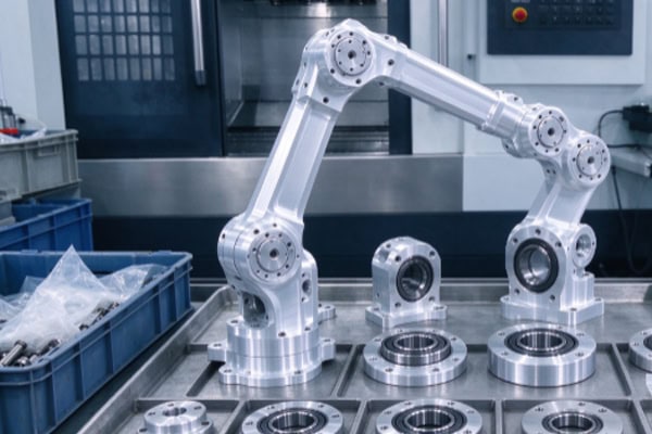
Control of Critical Dimensions, Surface Quality, and Batch Consistency
Smart manufacturing equipment often depends on multiple components working together. Dimensional deviations in a single part may affect the assembly of the entire mechanism. For precision interfaces, sensor mounts, and positioning fixtures, manufacturers should identify critical dimensions and inspection methods based on engineering drawings. First-article inspection and batch sampling can then be used to control quality.
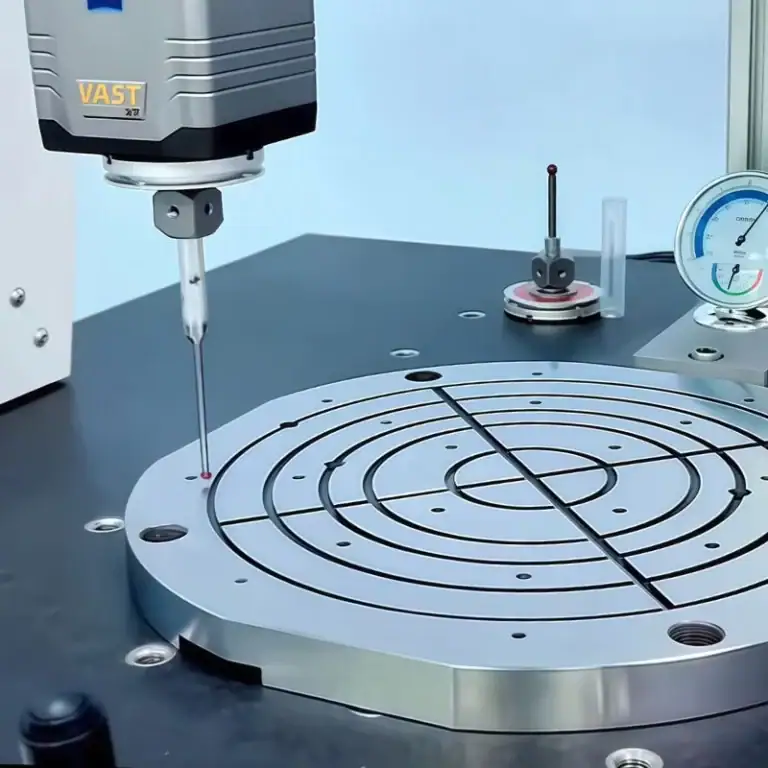
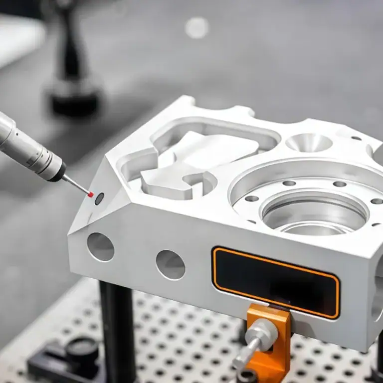
- Dimensional and hole-position inspection: Use calipers, micrometers, bore gauges, or dedicated gauges to inspect critical dimensions. Coordinate measuring machines may be used for position, flatness, and other geometric tolerances when required.
- Surface and edge inspection: Check for burrs, scratches, visible tool marks, and machining defects that could affect assembly or damage adjacent components.
- Assembly interface verification: Confirm that threads, mating holes, locating surfaces, and connection structures meet assembly requirements. Trial assembly or functional testing may be necessary.
- Batch quality traceability: Retain material information, CNC program versions, critical dimension records, and inspection results to help identify dimensional changes and trace production issues.
When components undergo anodizing, passivation, or other surface treatments, manufacturers should assess how the treatment affects final dimensions and fit. For holes and mounting surfaces with tight tolerances, appropriate machining allowances should be included during process planning to protect final assembly accuracy.
Long-Term Operational Stability and Compatibility with Smart Equipment
Smart manufacturing robot components may operate for extended periods under repetitive motion, continuous vibration, mechanical loads, or demanding industrial conditions. Brackets and connectors require adequate stiffness, guide components need suitable wear resistance, and sensor mounting structures must maintain reliable positioning. For moving components, manufacturers should also evaluate how fit clearance, deformation under load, and long-term wear may affect equipment accuracy.
CNC machining plans should match materials and structural designs to the component’s intended function. Thin-wall sections, sharp corners, and areas of concentrated stress require particular attention during manufacturing. For lightweight components, structural geometry can be optimized while maintaining the required strength and stiffness. Frequently used positioning components should be designed with contact-surface wear resistance and ease of maintenance in mind.
Modular components should also use consistent interface dimensions and positioning references to simplify connections with robot bodies, sensors, actuators, and automated workstations.
CNC machining solutions for smart manufacturing robot components support customized parts for vision inspection, automated assembly, precision positioning, and material handling. Through appropriate material selection, process planning, critical dimension inspection, and batch quality management, manufacturers can improve assembly consistency and operational reliability. Each manufacturing project should be planned according to component drawings, operating conditions, production volume, and acceptance criteria, providing precision components that support reliable smart manufacturing equipment.