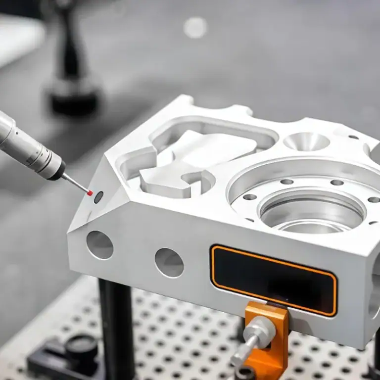
Surface finish symbols are a compact way to tell machinists, inspectors, and suppliers how a manufactured surface should perform. A small callout on an engineering drawing can define roughness, material removal, machining allowance, lay direction, and sometimes the required manufacturing process. Misreading that callout can lead to unnecessary polishing, incorrect machining, inspection disputes, or parts that meet dimensions but fail in service.
This guide explains surface finish symbols, drawing callouts, Ra and Rz values, common CNC surface levels, lay symbols, ISO and ASME practices, machining effects, inspection methods, cost considerations, and practical ways to specify surface finish correctly for CNC machined parts.
What Are Surface Finish Symbols?
Surface finish symbols are standardized drawing marks used to communicate surface texture requirements. They tell the manufacturer whether a surface needs controlled roughness, whether material removal is required or prohibited, and whether additional requirements such as lay direction or process notes apply.
What Surface Finish Symbols Tell A CNC Machinist
A surface finish symbol does more than describe appearance. It can indicate how smooth a surface must be and whether the specified result must be produced by machining.
For a CNC machinist, that requirement may influence tool selection, finishing allowance, cutting parameters, setup rigidity, and inspection planning.
A surface marked Ra 3.2 may be achievable directly from normal CNC machining, while Ra 0.4 may require grinding, polishing, or another finishing process.
Surface Finish Vs Surface Roughness Vs Surface Texture
Surface finish is a broad manufacturing term. It describes the overall condition of a surface after machining or finishing.
Surface roughness refers specifically to fine-scale peaks and valleys. Ra and Rz are commonly used to quantify these irregularities.
Surface texture includes roughness, waviness, lay, and other surface characteristics. For this reason, two surfaces can have the same Ra value but still look or behave differently.
Why Surface Finish Symbols Matter In Manufacturing
The correct surface condition can affect sealing, wear, friction, lubrication, fatigue life, coating adhesion, and appearance.
A shaft bearing surface, sealing face, and hidden structural pocket do not need the same finish.
Surface finish symbols allow designers to control critical areas without forcing the manufacturer to overfinish the entire part.
What Are The Main Types Of Surface Finish Symbols?
The basic surface texture symbol can be modified to show whether material removal is required, prohibited, or left open to the manufacturing process. Understanding these variations is the first step in reading machining surface finish symbols correctly.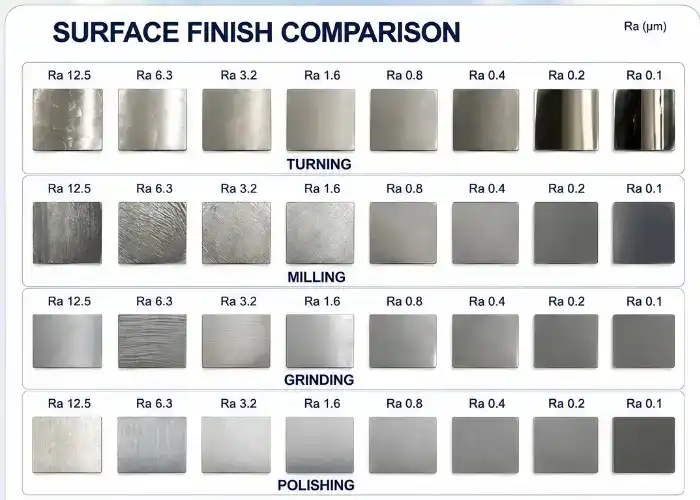
Basic Surface Texture Symbol
The basic symbol indicates that a surface texture requirement applies.
By itself, it does not necessarily state that machining is required.
Additional values, parameter names, or notes are added around the symbol to define the complete requirement.
Material Removal Required Symbol
When the symbol includes the machining bar, material removal is required.
This means the final surface must be produced through a material-removal process such as turning, milling, grinding, honing, or another controlled operation.
For CNC parts, this symbol is important because a cast or forged surface cannot simply be accepted in its original condition.
Material Removal Prohibited Symbol
A circle added to the surface texture symbol indicates that material removal is prohibited.
This is often relevant to cast, forged, molded, or otherwise near-net-shape surfaces.
Machining such a surface could remove an intentional skin, alter geometry, or violate the design requirement even if dimensional measurements remain acceptable.
Symbols Applied To Multiple Or All Surfaces
Some drawings use a general surface finish requirement that applies to all surfaces unless another finish is specified locally.
This saves drawing space but must be read carefully.
A local surface finish callout usually overrides the general requirement for that specific area.
How To Read A Surface Finish Callout
A complete surface finish callout may include the roughness parameter, limit value, process requirement, lay direction, machining allowance, and additional notes. The symbol must therefore be read as a complete package instead of focusing only on the Ra number.
Roughness Parameter And Limit
The most familiar parameter is Ra, but drawings may also specify Rz or other parameters.
The value defines the allowable texture level, usually in micrometers or microinches.
A callout such as Ra 1.6 therefore does not simply mean “make the surface look smooth.” It establishes a measurable acceptance requirement.
Manufacturing Process Or Treatment
A drawing can specify a required process when surface function depends on how the texture is created.
For example, grinding may be requested rather than simply asking for a low Ra value.
This can matter because a ground surface and a milled surface can have similar Ra values but different lay, waviness, and contact behavior.
Surface Lay Direction
Lay describes the predominant direction of the surface pattern.
The drawing may require the pattern to be parallel, perpendicular, crossed, circular, radial, or multidirectional relative to a reference.
This is especially important on sealing and sliding surfaces.
Machining Allowance
A surface finish callout may also state how much material should remain for a later finishing operation.
For example, rough machining may intentionally leave stock for grinding after heat treatment.
If the allowance is ignored, the finishing operation may not have enough material to correct distortion or achieve final dimensions.
Additional Surface Texture Requirements
Some surfaces need more information than a single Ra value.
The drawing may define multiple roughness parameters, production method, lay direction, or other functional notes.
When the callout becomes complex, the manufacturer should confirm interpretation before production rather than assume intent.
What Do Ra, Rz, Rq, And Rt Mean?
Ra is the most common surface roughness parameter, but it does not fully describe every surface. Rz, Rq, and Rt provide additional information about peak height, valley depth, and overall profile variation.
Ra: Arithmetic Average Roughness
Ra is the arithmetic average of the absolute deviations of the measured roughness profile from its mean line.
It is popular because it gives a simple numerical value that is easy to compare between surfaces.
However, averaging can hide isolated defects. Two surfaces can have the same Ra even when one has deeper valleys.
Rz: Peak-To-Valley Roughness
Rz evaluates peak-to-valley height over defined sampling lengths.
It is more sensitive to pronounced peaks and valleys than Ra.
For sealing, wear, or contact surfaces, Rz may provide more useful information when deep scratches or high peaks could affect performance.
Rq: Root Mean Square Roughness
Rq uses a root mean square calculation.
Because larger deviations have greater influence on the result, Rq responds more strongly to severe profile variation than Ra.
It is less common on ordinary CNC drawings but useful in detailed surface analysis.
Rt: Total Profile Height
Rt represents the total vertical distance between the highest peak and lowest valley in the evaluated profile.
This makes it sensitive to isolated scratches, gouges, or sharp peaks.
A surface can pass Ra while still showing an unusually high Rt if one major defect exists.
When To Use Ra Vs Rz
Ra works well for general machining specifications and routine inspection.
Rz becomes more useful when peak-to-valley behavior directly affects sealing, lubrication, wear, or contact.
The important point is that Ra and Rz should not be treated as direct equivalents.
What Surface Finish Values Are Common In CNC Machining?
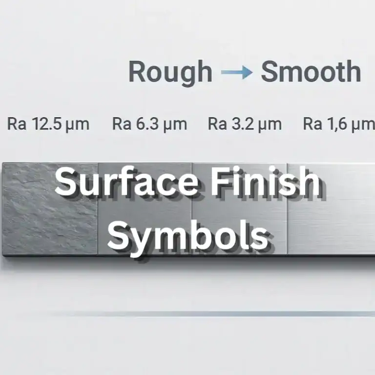
Common CNC surface finish values range from relatively rough machined surfaces around Ra 6.3 to fine functional finishes around Ra 0.8 or lower. The required value should match part function because lower Ra generally increases process time and cost.
| Typical Ra | General Use |
| 6.3 µm | Rough machining and noncritical surfaces |
| 3.2 µm | General CNC machined surfaces |
| 1.6 µm | Precision machined surfaces |
| 0.8 µm | Fine functional surfaces |
| 0.4 µm | High-quality precision finish |
| 0.2 µm And Below | Specialized finishing processes |
Ra 6.3 For Rough Machined Surfaces
Ra 6.3 can be suitable for hidden structural areas or surfaces that do not seal, slide, or require close visual control.
The main goal at this level is usually efficient material removal rather than appearance.
The actual finish can still vary depending on whether the surface is milled, turned, or produced by another process.
Ra 3.2 For General CNC Machining
Ra 3.2 is common for general machined components such as housings, brackets, plates, and structural features.
It provides a practical balance between machining speed and surface quality.
Many parts do not require a smoother finish unless the surface performs a specific functional role.
Ra 1.6 For Precision Machined Surfaces
Ra 1.6 usually requires more controlled finishing.
A dedicated finishing pass, sharp tool, stable workholding, lower feed, and good machine rigidity may be needed.
It is often suitable for more demanding mating surfaces, visible surfaces, and precision mechanical features.
Ra 0.8 For Fine Functional Surfaces
Ra 0.8 generally requires tighter control of cutting conditions.
Tool runout, vibration, coolant, cutting edge condition, and finishing allowance become more important.
This level may be used on shafts, bearing surfaces, sealing areas, or other functional interfaces.
Ra 0.4 And Below For High-Precision Finishing
Ra 0.4 or lower often pushes normal milling and turning toward their practical limits.
Grinding, honing, lapping, or polishing may provide a more stable and economical route.
The best process depends on geometry, tolerance, material, and required surface function.
Why Lower Ra Does Not Always Mean Better Performance
A smoother surface is not automatically better.
Some lubricated interfaces need enough texture to retain oil, while certain coatings need controlled roughness for adhesion.
The correct Ra value should therefore come from function, not from the assumption that a smaller number means higher quality.
What Do Surface Lay Symbols Mean?
Surface lay symbols define the dominant direction of machining marks. Lay direction can affect sealing, friction, lubrication, wear, and appearance even when the measured Ra value remains unchanged.
Parallel Lay
Parallel lay means the surface pattern runs parallel to the reference direction.
This may be created by grinding, milling, or another directional process.
Its suitability depends on how the mating part moves or seals against the surface.
Perpendicular Lay
Perpendicular lay runs across the reference direction.
This may improve or reduce functional performance depending on sliding direction or fluid flow.
For moving interfaces, the relationship between lay and motion should be considered carefully.
Crossed And Multidirectional Lay
Crossed lay contains intersecting surface patterns.
Multidirectional lay has no single dominant direction.
These patterns can be produced by polishing, certain grinding methods, or overlapping machining paths.
Circular And Radial Lay
Circular lay follows a circular path around a center.
Radial lay extends outward from a central point.
These are common on faced rotational components and can matter significantly for sealing applications.
Why Lay Direction Matters For Sealing, Wear, And Sliding
A sealing face may have an acceptable Ra but still leak if tool marks create a continuous path across the seal.
Similarly, sliding surfaces can behave differently depending on whether movement follows or crosses the machining marks.
This is why engineering drawings sometimes specify both roughness and lay.
How Are Surface Finish Symbols Shown On Engineering Drawings?
Surface finishing symbols in drawings may be attached directly to a surface, placed on a leader, or specified through a general note. Their location determines which surfaces are controlled and whether a local requirement overrides a general finish.
Symbols Placed Directly On A Surface
A symbol placed directly against a surface line normally applies to that specific surface.
This is common when only a few faces need special roughness.
The machinist should confirm exactly which edge or surface the symbol refers to.
Symbols On Leaders And Extension Lines
Leader lines allow a finish requirement to point clearly to a particular feature.
They are useful when the drawing is crowded or when the controlled surface is small.
Extension lines can also carry surface texture information depending on drawing practice.
General Surface Finish Notes
A general note may specify that all unspecified machined surfaces require, for example, Ra 3.2.
This avoids repeating the same callout many times.
Local symbols then define exceptions that require a different finish.
Different Finish Requirements On The Same Part
A single CNC part can contain several surface requirements.
A sealing face may require Ra 0.8, a bearing seat Ra 1.6, and noncritical pockets Ra 3.2 or rougher.
This is usually more economical than specifying the tightest finish everywhere.
How To Avoid Ambiguous Surface Finish Callouts
The drawing should clearly identify the roughness parameter, value, controlled surface, applicable standard, and any required lay or process.
Avoid relying on undocumented company conventions when suppliers may interpret the drawing differently.
A clear callout reduces both manufacturing risk and inspection disputes.
What Standards Apply To Surface Finish Symbols?
Surface finish symbols must be interpreted within the drawing standard that defines them. ISO and ASME systems use many similar concepts, but their notation and detailed rules are not always identical.
ISO 21920-1 Surface Texture Symbols
ISO 21920-1 provides the current ISO framework for indicating profile surface texture requirements on technical product documentation.
It defines how surface texture information is presented using graphical symbols.
Modern ISO-based drawings increasingly use this system.
Legacy ISO 1302 Surface Finish Drawings
Many existing drawings still follow ISO 1302 conventions.
Manufacturers therefore need to understand older symbols when working with legacy parts and long-running production programs.
The safest approach is to identify the standard stated on the drawing rather than assume the newest system automatically applies.
ASME Surface Texture Callouts
North American engineering drawings may follow ASME surface texture practices.
The graphical language is similar in purpose but may differ in presentation and interpretation details.
Suppliers working internationally should be comfortable reading both systems.
Why The Drawing Standard Must Be Confirmed Before Machining
A roughness value without context can be interpreted incorrectly.
Parameter notation, filtering rules, lay symbols, and default assumptions may depend on the specified standard.
Confirming the standard before programming helps avoid expensive rework later.
How Do Surface Finish Symbols Affect CNC Machining?
Machining surface finish symbols influence the entire process plan. They can change tool selection, cutting parameters, finishing passes, stock allowance, setup strategy, and whether a secondary process is needed after CNC machining.
Tool Selection And Cutting Geometry
Finishing tools need stable cutting edges and appropriate geometry.
Turning insert nose radius, milling cutter runout, flute geometry, and edge preparation all influence the resulting texture.
A tool chosen only for material removal rate may not be suitable for a tight roughness requirement.
Feed Rate, Speed, And Step-Over
Feed directly affects the spacing and height of tool marks.
In turning, higher feed per revolution generally produces a rougher theoretical profile.
In milling, smaller step-over can reduce scallop height, particularly on curved surfaces.
Cutting speed also affects chip formation and built-up edge.
Finishing Passes And Machining Allowance
A dedicated finishing pass allows the tool to remove a consistent amount of material under lower cutting load.
This improves repeatability.
If grinding or another secondary process follows, enough machining allowance must remain to correct distortion and reach the final dimension.
Milling Vs Turning Surface Patterns
Milling and turning can achieve similar Ra values but leave different tool marks.
Turning typically creates a helical pattern, while milling may create arcs, parallel passes, or scallops.
The process should therefore be selected based on both roughness and functional lay.
Grinding, Honing, Lapping, And Polishing Requirements
Very low roughness values may require processes beyond standard CNC cutting.
Grinding is useful for hardened precision surfaces.
Honing is common for bores, while lapping and polishing can create very fine finishes.
These additional processes should be considered during quotation rather than treated as unexpected rework.
How Are Surface Finish Requirements Measured And Inspected?
Surface finish inspection must match the drawing callout. Measurement method, direction, sampling length, and location can all affect the result, so inspection should be planned before production rather than after parts are complete.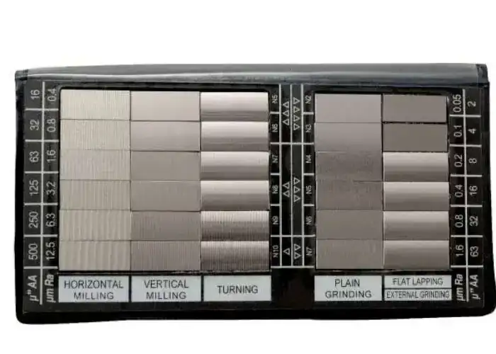
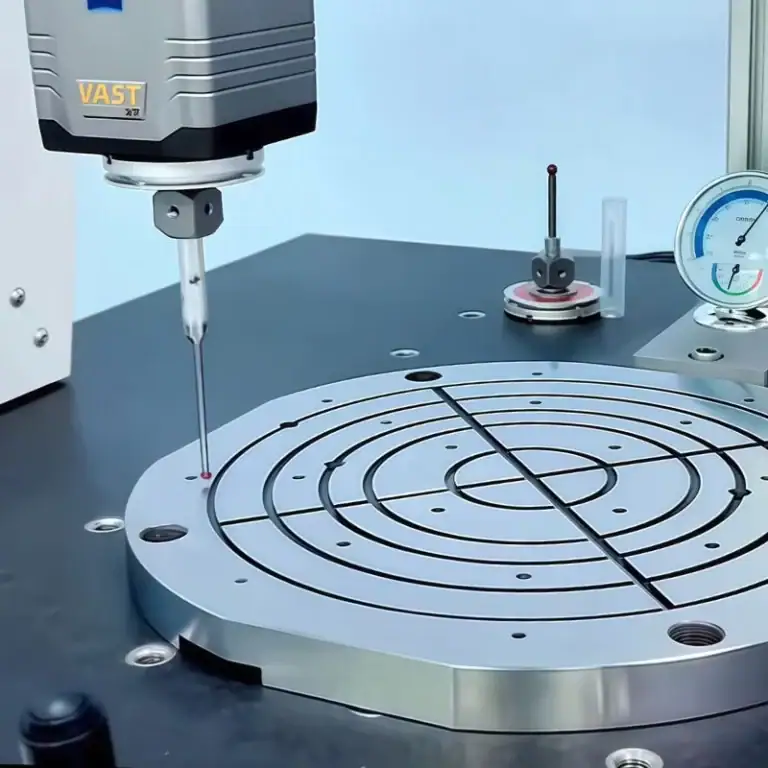
Contact Profilometer Measurement
A contact profilometer uses a stylus to trace the surface.
The instrument records height variation and calculates parameters such as Ra or Rz.
It is widely used for machined metal surfaces because it is practical and repeatable.
Optical And Non-Contact Measurement
Optical systems measure surface topography without physically touching the part.
They are useful for small features, soft materials, delicate surfaces, or shapes that are difficult to reach with a stylus.
The selected method should still be compatible with the drawing requirement.
Measurement Direction And Surface Lay
Measurement direction matters.
If the stylus moves parallel to the lay, it may record a lower roughness than when crossing the machining marks.
Critical inspection should therefore use a defined direction relative to the surface pattern.
Sampling Length And Evaluation Length
The instrument must use an appropriate sampling and evaluation length.
If the length is too short, the result may not represent the actual surface.
If inappropriate filtering is used, waviness may be included or meaningful roughness may be removed.
Matching Inspection To The Drawing Callout
The inspection plan should identify which parameter is measured, where it is measured, which direction is used, and which equipment is acceptable.
This is especially important when customer and supplier use different measurement systems.
Agreement before production prevents disputes later.
How Do Surface Finish Requirements Affect CNC Machining Cost?
Tighter surface finish requirements usually increase cost because they reduce process freedom. Lower Ra may require slower feeds, smaller step-over, dedicated tooling, secondary finishing, and more detailed inspection.
Lower Roughness Values Increase Machining Time
Reducing feed or step-over increases machining time.
On large faces or freeform five-axis surfaces, small changes in step-over can multiply the number of toolpaths.
A very fine finish can therefore have a major cycle-time impact.
Additional Tooling And Finishing Operations
A normal cutter may meet Ra 3.2, while Ra 0.4 may require grinding or polishing.
Each additional process adds setup, handling, tooling, and quality-control cost.
The part may also need transport between different machines or departments.
Inspection And Measurement Cost
Critical surface texture requires appropriate inspection equipment.
Measuring several surfaces with a profilometer or optical system takes more time than visually accepting ordinary machined surfaces.
Tighter specifications therefore increase both manufacturing and inspection effort.
When A Tighter Surface Finish Adds Little Functional Value
A hidden pocket that never seals, slides, or contacts another part may not benefit from Ra 0.8.
Specifying that finish anyway adds cost without improving function.
Engineering drawings should reserve demanding surface requirements for areas where they create measurable value.
What Are Common Surface Finish Drawing Mistakes?
Most surface finish specification problems come from over-specification, unclear callouts, incorrect parameter use, or failure to consider how the surface will actually be manufactured and measured.
Specifying A Lower Ra Than The Function Requires
Selecting Ra 0.4 because it looks more precise does not automatically improve the part.
If Ra 3.2 would perform equally well, the lower requirement only increases machining effort.
Surface finish should always have a functional reason.
Confusing Ra And Rz
Ra and Rz measure different characteristics.
Using one as a direct substitute for the other can lead to incorrect acceptance decisions.
The manufacturer should control the parameter actually specified on the drawing.
Applying One Finish Requirement To Every Surface
A single tight finish across an entire part is rarely economical.
Different surfaces perform different functions.
The drawing should distinguish critical sealing, sliding, bearing, cosmetic, and ordinary structural areas.
Ignoring Surface Lay Direction
Ra alone cannot describe directional texture.
For seals, sliding surfaces, or fluid interfaces, machining marks may influence performance even when roughness meets the numeric requirement.
Lay should be specified when function depends on it.
Using Legacy Symbols Without Confirming The Standard
Older drawings may follow different surface texture conventions.
If the manufacturing team assumes a newer interpretation without checking the drawing standard, the callout may be misunderstood.
Legacy drawings should therefore be reviewed carefully before production.
Specifying A Finish That Is Difficult To Measure
Deep pockets, narrow grooves, tiny bores, and complex curved surfaces can be difficult to inspect with a standard stylus profilometer.
A requirement that cannot be measured reliably creates acceptance problems.
Measurement access should therefore be considered during design.
How To Specify Surface Finish Correctly For CNC Parts
A good surface finish specification begins with function. Identify the surfaces that truly control sealing, wear, sliding, fit, coating, or appearance, then choose a roughness parameter and process requirement that can be manufactured and inspected consistently.
Identify Functional Surfaces First
Start by identifying which surfaces actually affect part performance.
These may include bearing seats, seal faces, sliding guides, mating interfaces, optical surfaces, or cosmetic areas.
Noncritical faces should generally remain under a normal machining finish unless another reason requires tighter control.
Select The Appropriate Roughness Parameter
Use Ra when an average roughness requirement is sufficient.
Use Rz or another parameter when peak-to-valley characteristics are more important.
Avoid adding multiple parameters unless they each control a real functional concern.
Match Roughness To The Manufacturing Process
The requested roughness should be realistic for the intended process.
A typical milled surface should not be forced to meet a polishing-level specification unless that additional operation is actually needed.
Design and manufacturing should work together to choose an achievable requirement.
Define Lay Direction Only When Function Requires It
Lay should be specified when it affects sealing, friction, lubrication, wear, or visual appearance.
If direction has no functional importance, leaving unnecessary restrictions off the drawing gives the manufacturer more flexibility.
Confirm The Applicable Drawing Standard
Clearly state whether the drawing follows the relevant ISO, ASME, or other standard.
This establishes how the symbol and parameter should be interpreted.
It is especially important when multiple suppliers or countries are involved.
Define Inspection And Acceptance Requirements
The drawing should make the requirement measurable.
For critical surfaces, the customer and supplier should agree on parameter, measurement method, location, direction, and acceptance criteria.
This turns a surface finish symbol from a vague visual target into a clear manufacturing requirement.
FAQs
Is Surface Finish The Same As Surface Roughness?
No. Surface roughness is one measurable part of surface texture, while surface finish is a broader term that can include roughness, waviness, lay, visual appearance, and process characteristics.
Does A Lower Ra Always Mean A Better CNC Surface?
No. Lower Ra means a smoother average profile, but it may not improve function. Some sliding, lubricated, coated, or sealing applications require controlled texture rather than the lowest possible roughness.
Can Milling And Turning Produce The Same Surface Finish?
They can achieve similar Ra values, but the surface patterns and lay direction are usually different. That difference can matter for sealing, wear, friction, and appearance.
Can Surface Finish Be Checked Visually?
Visual comparison can help with general production checks, but critical Ra or Rz requirements should be verified with an appropriate surface measurement instrument.
Conclusion
Surface finish symbols provide a compact way to communicate roughness, material removal, lay direction, machining allowance, and inspection requirements. Correct interpretation requires more than recognizing the symbol itself,Ra or Rz values, drawing standards, manufacturing process, functional surface behavior, and measurement conditions must all be considered together. Clear specifications help manufacturers achieve the required surface without adding unnecessary machining time or cost.
At TiRapid, we provide precision CNC machining and manufacturing services for prototypes and production parts. Our team reviews surface finish callouts, tolerances, materials, machining processes, and inspection requirements before production to help customers achieve reliable surface quality while balancing function, manufacturability, lead time, and cost.