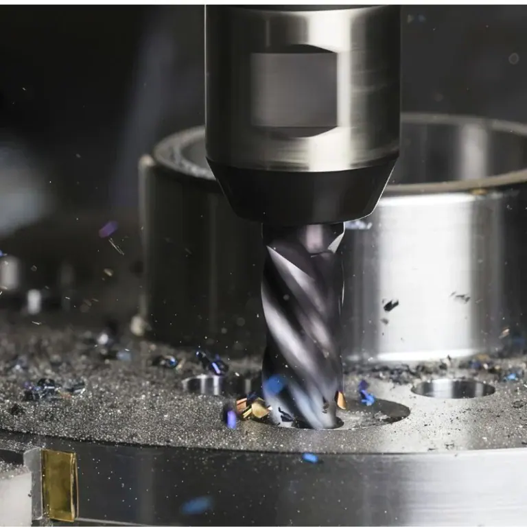
A CNC-machined plate can meet its thickness limits and still cause problems when it is bolted into an assembly. A bowed mounting face may leave gaps, distort a supported component, or distribute clamping loads unevenly. The drawing needs to communicate the surface shape that the assembly requires.
GD&T flatness provides that control. It defines an allowable zone for a surface without tying its orientation to another feature. Understanding the callout also means understanding what it leaves uncontrolled, how it interacts with size tolerances, and how inspection can separate actual form error from setup effects.
This guide explains the drawing rules, practical tolerance choices, and measurement decisions that engineers and buyers should resolve before ordering CNC parts.
What Is GD&T Flatness?
GD&T flatness is a form tolerance that requires the entire specified surface to lie between two parallel planes separated by the stated tolerance. The zone can change position and orientation to contain the surface, so flatness does not reference a datum.

What The Tolerance Zone Controls
Imagine placing two ideal, parallel sheets around the surface without bending either sheet. The smallest separation that contains the whole surface represents its minimum-zone flatness error. The drawing specifies the maximum permitted separation.
This is an area requirement. A surface can look straight along its edges yet contain a central crown, depression, or twist that violates flatness. Inspecting a few convenient lines does not necessarily reveal the worst variation across the face.
The zone is also independent of gravity. A surface does not need to be horizontal to satisfy flatness. Tilting a rigid part changes its orientation, but it does not change the shape of its surface.
Where Flatness Matters In Assemblies
Flatness is useful on mounting faces, sealing interfaces, fixture contact surfaces, and other areas where distributed contact matters. A more planar face can reduce unwanted gaps and the deformation needed to pull mating parts together.
The functional requirement still depends on the complete interface. A gasketed joint also depends on gasket behavior, fastener loading, and surface texture. Flatness alone does not establish leak tightness or guarantee assembly alignment.
A face can also serve as a datum feature while having its own flatness requirement. The datum designation identifies its reference role for other controls. The flatness callout controls that face’s form without referencing the datum it helps establish.
How To Read A Flatness Callout
A basic surface flatness callout contains the parallelogram symbol and a tolerance value, with an attachment identifying the controlled surface. Read the value as the total width of the tolerance zone, use the drawing’s units, and do not add a datum reference.
Symbol, Value, And Surface Attachment
The flatness symbol resembles a slanted parallelogram, commonly represented in text as ▱. In the feature control frame, it precedes the tolerance value. The leader or drawing attachment determines which feature the requirement controls.
For a teaching example, consider a surface callout with a value of 0.05 on a drawing that uses millimeters. All points of the specified surface must fit between parallel planes separated by 0.05 mm. The value is not a plus-or-minus allowance, and the zone is not automatically centered on the nominal CAD face.
Three details deserve attention when reviewing the drawing:
- The leader identifies the intended face rather than a neighboring edge or size dimension.
- The drawing defines the units, applicable standard, and revision.
- Any limited area, local requirement, or inspection condition is identified clearly.
A datum letter in an ordinary flatness feature control frame signals a problem to resolve. If the intended requirement is orientation relative to another face, parallelism or another orientation control may be appropriate.
Surface Flatness And Derived Median Plane Flatness
Surface flatness controls one actual face. Under ASME rules, flatness can also be applied to the derived median plane of an appropriate feature of size, such as a plate’s width or thickness.
In that application, the controlled feature is the collection of derived median points between opposing surfaces. It is not either individual face. The attachment to the size dimension is therefore a meaningful part of the specification.
Material condition modifiers require this distinction. An ordinary single-surface flatness requirement does not accept maximum material condition (MMC) or least material condition (LMC) modifiers. Eligible derived median plane controls can use these modifiers under the applicable ASME rules. Departure from the specified material condition can permit additional geometric tolerance, often called bonus tolerance.
Do not transfer that additional allowance to a surface callout. Nor should a passing median plane result be treated as proof that both physical faces satisfy separate surface flatness requirements.
Flatness Vs Parallelism, Straightness, And Surface Roughness
Choose the control that matches the functional problem. Flatness limits the form of a surface, parallelism relates its orientation to a datum, surface straightness controls individual line elements, and roughness describes surface texture using its specified parameters and evaluation conditions.

What Each Requirement Answers
| Requirement | Main Question | Datum Needed? | Typical Reason To Use It |
| Surface flatness | Is the specified face sufficiently planar? | No | Support or mating contact |
| Surface parallelism | Is the face properly oriented to a reference? | Yes | Alignment to a mounting datum |
| Surface straightness | Is a specified line element sufficiently straight? | No | Form along a defined direction |
| Surface roughness | Does the texture meet the specified parameter? | Not applicable to this comparison | Friction, wear, or sealing behavior |
A uniformly tilted planar face can satisfy flatness while failing parallelism to a mounting datum. Conversely, an ordinary surface parallelism zone consists of parallel planes oriented to the datum. Containment within that zone also limits surface form to the same zone width.
Adding a separate, equally large flatness requirement to that same surface may therefore add no useful restriction. A tighter flatness control can be justified if local contact demands better form than the orientation tolerance provides.
A smooth face can still be bowed. A planar face can still have rough machining marks. A roughness value such as Ra is not a substitute for a flatness requirement, and flatness is not a surface texture specification.
How Size Tolerances Affect Form
Thickness and flatness describe different characteristics, but their requirements are not always independent. Under ASME Y14.5, Rule 1 generally imposes a perfect-form boundary at maximum material condition for a regular feature of size, unless an applicable exception or override applies.
Local thickness measurements alone therefore do not establish compliance with all ASME size requirements. A statement that thickness tolerances never control form would be misleading.
ISO GPS uses the independency principle as its general basis, with additional requirements where indicated. Read the governing standard and drawing notes before deciding what form control the size limits already provide. Avoid applying a universal flatness-to-size inequality across every drawing system and feature type.
How To Specify Flatness For CNC Parts
Select flatness from the interface’s functional needs, identify exactly where it applies, and define the condition in which the part must comply. A useful specification gives manufacturing and inspection teams the same target without tightening unrelated surfaces.
Start With Contact And Assembly Behavior
Ask what happens if the face is bowed, twisted, or crowned. Does the component rock during installation? Can a mating part tolerate a gap? Will tightening the bolts bend a sensitive housing or disturb a sliding assembly?
These questions connect the tolerance to an observable failure mode. They also reveal when another control is needed. If the critical issue is the angle between a mounting face and a reference face, flatness alone will leave the relationship uncontrolled.
For purchasing teams, this distinction helps clarify supplier questions. A request to change flatness should explain the affected contact or assembly function. A blanket request for the tightest achievable value gives little basis for evaluating cost or feasibility.
Define The Controlled Area
An ordinary full-surface requirement applies across the identified surface. Do not assume that each milling pass, probe path, or selected patch gets its own independent acceptance zone.
Interrupted contact areas need particular care. If several separated pads must support one rigid component together, individually controlling each pad’s flatness does not establish that the pads are coplanar. Their mutual relationship needs an appropriate shared requirement under the selected standard.
Local or per-unit flatness can address shorter-scale variation, but it must be specified correctly. A local requirement alone does not necessarily limit the overall bow of a long face. Where both effects matter, define the overall and local controls explicitly.
Define The Inspection Condition
A thin plate can change shape under its own weight, probe contact, or clamping. The drawing and inspection plan should establish whether compliance is required in a free state or under a defined restrained condition.
If restraint represents the intended assembly, document the support locations and relevant loading or fastening conditions. Otherwise, one supplier may measure a freely supported part while another pulls it against a fixture, producing results that answer different questions.
Also clarify the acceptance stage. A requirement intended for the delivered component needs to be evaluated after the specified operations. Inspection before a later treatment is not automatically evidence of final compliance.
Align The Drawing With The Purchase Request
Send suppliers the same drawing revision and identify which interfaces are critical to acceptance. Include the material condition, finishing sequence, quantity, and required inspection documentation so that quotations address equivalent work.
If a supplier proposes a different tolerance or a restricted measurement area, ask how the change affects assembly function and acceptance. Review the proposal before issuing an approved drawing revision. An email agreement about a convenient probe path should not silently redefine a full-surface requirement.
Also distinguish a one-time sample result from evidence supporting repeat production. A satisfactory first article shows what was measured on that article. For ongoing orders, discuss how the supplier will maintain the setup, verify relevant characteristics, and respond to process changes. The required evidence should reflect the interface’s importance and the purchasing agreement.
How To Measure Flatness Correctly
Reliable flatness measurement combines suitable equipment, representative surface coverage, controlled support, and an evaluation method that matches the specification. A precision instrument alone cannot correct an unsuitable setup or a sampling plan that misses the surface’s worst regions.
Prepare The Surface And Supports
Clean the measurement surface and support points. Remove loose chips and contamination without altering the part’s actual geometry. Inspect suspicious burrs or raised damage rather than treating every unexpected high reading as instrument noise.
Support the part consistently and avoid forcing it into shape. For flexible components, support placement and gravity direction belong in the measurement procedure. The aim is to measure the specified condition reproducibly.
Allow the part and measurement system to reach a suitable thermal condition. A recently machined component and an inspection room may be at different temperatures. Changing temperatures and temperature gradients can affect the geometry or the measurement result, particularly when the permitted variation is small.
Surface Plate And Indicator Measurement
A calibrated surface plate and indicator can support useful flatness checks. The setup must separate the surface’s form from its overall tilt relative to the plate.
Simply resting a part on its opposite face and sweeping the top can include errors from the supporting face and the part’s orientation. The raw maximum-minus-minimum reading is a height range in that setup, not automatically the minimum-zone flatness error of the upper face.
Adjustable supports allow the operator to change orientation and seek the smallest containing range. Coverage must extend across the controlled area, including likely crowns, depressions, and edges where appropriate. Manual methods require a documented procedure and care with contact force and reading consistency.
CMM Measurement
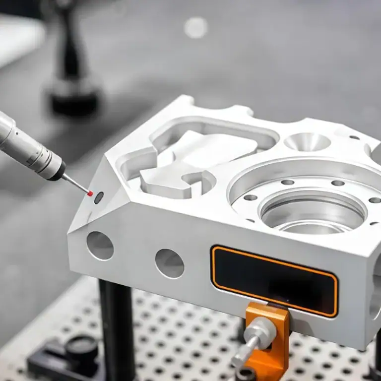
A coordinate measuring machine collects surface coordinates for geometric evaluation. It can be useful when the inspection also includes dimensions, hole locations, and relationships to datums.
Point distribution matters as much as convenience. Measuring only corners can miss a central crown. Sampling only the center can miss edge lift. Probe paths should reflect the face’s size, shape, machining pattern, and likely deformation.
Three non-collinear measured points define a plane and cannot reveal deviation among themselves from that plane. More extensive sampling is needed to assess surface form. No single point count is adequate for every part, and a sparse passing result does not demonstrate that unsampled areas comply.
Optical And Scanning Methods
Optical profilers, suitable scanning systems, and interferometric techniques can provide denser surface information without conventional point-by-point contact. This can help reveal spatial patterns that a sparse probe program misses.
Select the system for the actual surface and tolerance. Field of view, surface reflectivity, access, achievable uncertainty, and data processing all matter. A larger point cloud is useful only when the data represent the surface reliably.
Agree on filtering and invalid-data handling before acceptance testing. Removing a genuine high spot changes the evaluated geometry. A documented optical artifact can require correction, but deleting inconvenient points is not a valid way to make a part pass.
Minimum Zone Vs Least-Squares Evaluation
Minimum-zone evaluation seeks the smallest separation between parallel planes containing the measured surface points. Least-squares evaluation first finds a plane that minimizes squared point deviations. These methods solve different problems and can produce different reported flatness values from the same data.
Why The Fitting Method Matters
For a basic minimum-zone requirement, the containing planes may rotate as well as translate to enclose the points as tightly as possible. A least-squares plane represents an averaging objective rather than directly minimizing the containing zone.
If a report calculates a peak-to-valley range normal to the least-squares plane, that range cannot be smaller than the optimal minimum-zone range for the identical point set. It can therefore report a value above the limit even when minimum-zone evaluation of those points would be below it.
The software setting should match the drawing’s evaluation requirements. A label such as “best fit” is not sufficiently precise because software can use that phrase for different algorithms. Confirm the actual fitting objective and report parameter.
Neither algorithm recovers missing surface information. A mathematically correct minimum-zone fit to sparse or distorted data can still misrepresent the actual part.
A Flatness Calculation Example
Consider an illustrative dataset evaluated in its minimum-zone orientation. The extreme signed distances, measured normal to the evaluated plane, are as follows.
| Item | Illustrative Value |
| Highest signed distance | +0.018 mm |
| Lowest signed distance | −0.014 mm |
| Containing zone width | 0.032 mm |
| Drawing flatness limit | 0.05 mm |
The width is calculated by subtracting the lowest signed distance from the highest: 0.018 − (−0.014) = 0.032 mm. This is the total range, not either individual distance or their average.
The sampled result is below the stated limit. Acceptance should follow the agreed decision rule and account for measurement uncertainty and surface coverage.
What Affects Flatness During CNC Machining?
Final flatness depends on the interaction of workholding, material stress, cutting forces, machine condition, and temperature. Choose the manufacturing route for the actual geometry and required acceptance condition rather than assigning a universal capability to CNC milling.
Workholding And Material Stress
A fixture needs to resist cutting loads without bending the component. Unsupported spans can deflect under the cutter, while excessive clamping can hold a flexible blank in an artificial shape. A surface machined in that condition may change after release.
Place supports and clamps so that loads travel through adequately supported regions. For thin sections or broad plates, compare the supported condition with the condition required for acceptance before finalizing the setup.
Residual stress is a separate concern. Removing material changes the balance of stress within a blank, and machining can introduce additional stresses near the surface. These effects can distort thin aluminum components even when the tool follows its programmed path accurately.
The process plan may therefore require staged material removal, a different stock condition, or an appropriate stabilization step. Such choices depend on material and geometry. Thermal stabilization and stress relief are different operations and should be specified separately.
Cutting Strategy And Finishing Route
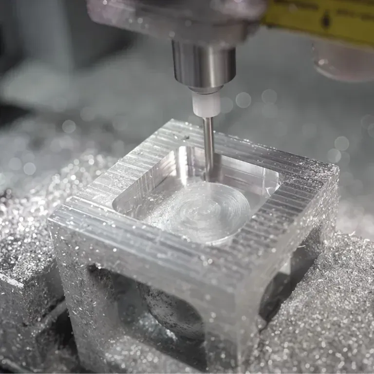
Face milling is commonly used to generate planar surfaces. Cutter selection, tool condition, runout, engagement, and the direction of cutting forces influence the result. Machine alignment and stability also affect the surface produced.
Improve rigidity and cutting behavior before assuming that a lighter finishing pass will solve the problem. A pass that reduces visible tool marks may still leave overall bow or setup-related distortion.
Where milling cannot meet the required form economically, a compatible grinding or lapping route may be considered. Those processes still require suitable support, material compatibility, and inspection. A process name alone does not guarantee a specific flatness value.
Evaluate feasibility using the complete part: material, span, thickness, pockets, remaining stock, finishing sequence, and inspection condition. The same numerical tolerance can present very different challenges on a compact block and a broad, thin plate.
What To Include In A Flatness Inspection Report
A useful inspection report connects the measured result to the correct drawing requirement and records enough of the method to make the result understandable. Reporting a flatness number without its surface, condition, or evaluation basis can leave an acceptance dispute unresolved.
For critical interfaces, agree on the following information before production:
- Part number, drawing revision, and governing standard.
- Identification of the controlled face or derived feature.
- Flatness limit and measurement units.
- Equipment and applicable calibration status.
- Support, restraint, and environmental conditions relevant to the result.
- Point distribution, scan coverage, and agreed data exclusions or filters.
- Evaluation method and reported flatness value.
- Measurement uncertainty information and the acceptance decision rule where required.
A deviation map can help identify whether variation concentrates near a pocket, edge, or unsupported region. It supplements the numerical result, but the color scale and evaluation settings must be understood before comparing reports.
For procurement, the most useful supplier discussion happens before machining. Resolve whether both parties are measuring the same feature, at the same production stage, under equivalent conditions. This makes a report actionable if a result approaches or exceeds the limit.
FAQs
How Do You Measure Flatness On CNC-Machined Parts?
Measure flatness using a suitable indicator setup, CMM, or optical measurement system. Clean the surface, support the part without distorting it, and collect measurements across the controlled area. For minimum-zone evaluation, determine the smallest distance between two parallel planes containing the measured points. Simply resting the part on its opposite face and sweeping the top can include tilt and support effects, so the raw indicator range is not automatically the flatness error.
What Is The Difference Between Flatness And Parallelism?
Flatness controls the form of a surface without referencing a datum. Parallelism controls its orientation relative to a specified datum. A planar surface can meet flatness requirements while failing parallelism because it is tilted relative to the reference. A surface parallelism tolerance also limits form within its oriented tolerance zone, so a separate flatness requirement is useful when the surface needs tighter form control.
Why Do Different Measurement Methods Give Different Flatness Results?
Flatness results can differ because of measurement coverage, support conditions, contact force, temperature, and evaluation settings. Sparse measurements may miss a crown or depression, while clamping can distort a flexible part. Software using a least-squares plane can also report a larger peak-to-valley range than minimum-zone evaluation of the same points. Before comparing results, confirm that both methods evaluate the same surface under equivalent conditions using compatible sampling and calculation procedures.
Conclusion
GD&T flatness turns a general request for a flat face into a defined geometric requirement. Apply it to the correct feature, distinguish form from orientation and texture, and choose a tolerance that supports the interface’s function.
Manufacturing and inspection need to work toward that same requirement. Support conditions, surface coverage, evaluation settings, and the stage of acceptance can matter as much as the number in the callout.
TiRapid provides CNC machining services for custom parts. Send your drawing and 3D model with the material, critical flatness requirements, finishing requirements, and intended assembly conditions for a project-specific manufacturing assessment. Clear requirements provide a stronger basis for discussing the production route and inspection expectations before ordering.