A turbine blade is a shaped component that helps convert energy from a moving fluid into mechanical power. In a gas or steam turbine, rotating blades work with stationary vanes to direct the flow and turn a rotor.
Although blades may look similar, their designs vary with the turbine type, operating stage, material, and working environment. An aircraft engine blade exposed to hot combustion gas faces different requirements from a steam turbine blade operating in a wet-steam region.
This guide explains turbine blade function, types, key design features, materials, and inspection considerations. It also outlines what engineers and buyers should review when discussing a blade project with a manufacturer.
What Is A Turbine Blade?
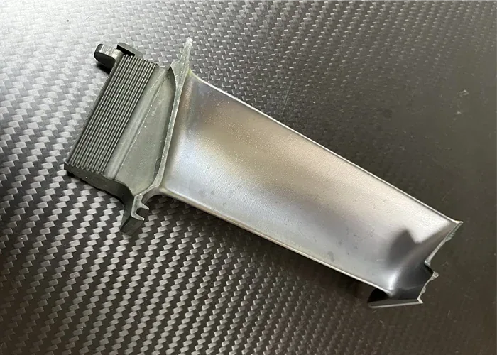
A turbine blade is an airfoil-shaped component that interacts with a flowing fluid. A rotating blade transfers energy from the flow to the rotor, while a stationary vane directs and conditions the flow entering or leaving a blade row.
Rotating Blades And Stationary Vanes
A rotating blade is attached to a disk, drum, or another rotor structure. As gas or steam passes through the blade row, the flow changes direction and transfers energy to the rotating assembly. The shaft can then drive a compressor, generator, propeller, or other equipment.
A stationary vane does not rotate with the shaft. It is supported by the surrounding structure and guides the working fluid toward the next row. In a turbine, the vane passage may also accelerate the flow as pressure falls.
How Are Blades Identified?
In everyday use, the word “blade” may refer to either rotating or stationary airfoils. For engineering and purchasing, the distinction matters because the two components have different mounting arrangements, loads, and functions.
The airfoil’s shape is only part of the component. Its root, platform, tip, and any cooling or sealing features must also suit the surrounding assembly.
What Is A Turbine Blade Used For?
A turbine blade is used to extract energy from moving gas or steam and transfer that energy to a rotating shaft. The shaft power supports the function of the larger system, such as aircraft propulsion or electricity generation.
Aircraft And Industrial Gas Turbines
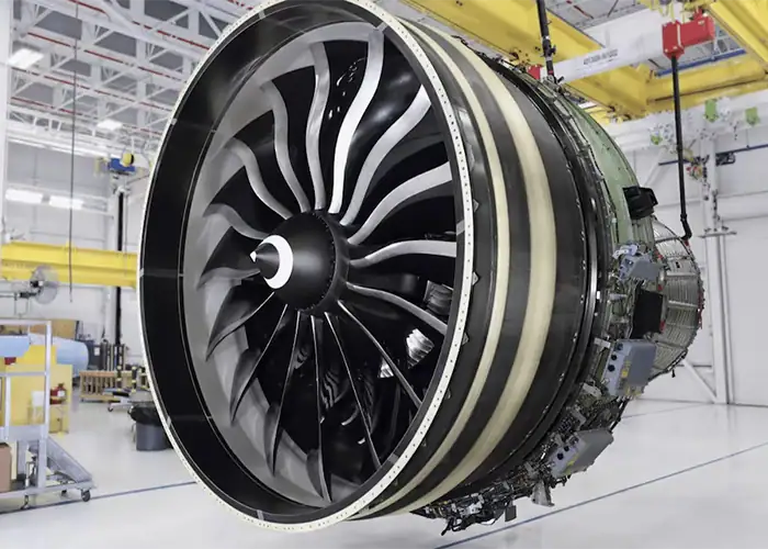
In an aircraft gas turbine, fuel burns in compressed air before the hot gas enters the turbine. The turbine extracts part of that gas energy to drive the compressor and, depending on the engine design, a fan, propeller, or other equipment.
In an industrial gas turbine, shaft power may drive a generator or a mechanical load. The blade design must suit the machine’s operating profile, fuel environment, maintenance strategy, and required output.
Steam Turbines
A steam turbine blade performs an energy-transfer role using steam rather than combustion gas. Stationary and rotating rows guide and turn the steam as it expands through the turbine. The shaft can drive an electrical generator or other machinery.
Turbine Blades And Compressor Blades
Turbine and compressor blades can both have airfoil shapes, but their roles differ.
A compressor receives shaft power and uses rotating blades to increase the pressure of the incoming gas. A turbine extracts energy from the flow and delivers shaft power. Their blade shapes, materials, temperatures, and loading conditions are designed around these different tasks.
A fan blade at the front of an aircraft engine is also a different component from a turbine blade in the hot section. When discussing a drawing or a replacement part, identify the actual engine section rather than relying only on the word “blade.”
What Are The Main Types Of Turbine Blades?
Turbine blades can be classified by their movement, turbine stage, working fluid, and energy-conversion design. These classifications describe different aspects of a component, so a single blade can belong to more than one category.
Rotating Blades And Stationary Vanes
Rotating blades form part of the rotor assembly. They receive force from the working fluid and transfer torque to the shaft. Their roots or integral connections must carry the resulting loads while maintaining the intended airfoil position.
Stationary vanes are fixed to a casing or support structure. They direct the flow into a rotating row and help establish the required inlet conditions. They also experience thermal and aerodynamic loads, but they do not carry the same rotational loading as a moving blade.
The terms used on drawings vary by manufacturer. A stationary airfoil may be called a vane, nozzle vane, guide vane, or fixed blade. Confirm the component’s location and mounting arrangement when interpreting the terminology.
High-Pressure And Low-Pressure Turbine Blades
Aircraft gas turbines commonly contain high-pressure and low-pressure turbine sections. The exact arrangement depends on the engine.
High-pressure turbine blades are located closer to the combustor and can face particularly severe thermal conditions. Their designs may include internal cooling and protective coatings.
Low-pressure turbine blades operate farther downstream. Their temperature and loading environment differs, and their geometry may be longer or more strongly twisted in some designs. Selected low-pressure turbine applications use titanium aluminide materials where the design and manufacturing route support them.
These categories identify the component’s location. They do not define one universal material or geometry for all engines.
Impulse And Reaction Blading
Impulse and reaction describe how pressure changes and energy transfer are distributed through a turbine stage.
In an idealized impulse stage, most of the pressure drop occurs in the stationary nozzle. The resulting flow then changes direction through the moving blade row and produces force.
In a reaction stage, pressure also falls through the moving blade passage. The rotor therefore experiences the effects of both flow turning and expansion through the moving row.
Practical turbine stages are not always purely impulse or purely reaction. Their degree of reaction can vary with the design and, in some cases, along the blade span. The terms are useful for understanding the stage, but they do not replace the complete design definition.
Gas Turbine And Steam Turbine Blades
A gas turbine blade interacts with hot gas produced by a combustion process. Material selection, cooling, oxidation, and thermal fatigue can be important concerns, especially in hot sections.
A steam turbine blade interacts with steam as it expands through the machine. Conditions change from the inlet to the exhaust. Depending on the stage, designers may need to address high-temperature strength, corrosion, moisture, or droplet erosion.
A steam turbine blade should therefore be identified by its stage and operating environment. A blade from a relatively dry, hot region may not have the same design priorities as a long blade operating near the wet-steam end.
How Do The Classifications Relate?
The following categories describe different aspects of a turbine blade. For example, one component can be a rotating blade in a low-pressure turbine and also belong to a stage with a particular degree of reaction.
| Classification | Examples | What It Describes |
| Movement | Rotating blade or stationary vane | Whether the component turns with the rotor |
| Engine section | High-pressure or low-pressure turbine | Location within the turbine |
| Stage behavior | Impulse or reaction | Distribution of pressure drop and flow turning |
| Working fluid | Combustion gas or steam | The operating environment |
What Are The Main Parts Of A Turbine Blade?
The main features of a turbine blade are the airfoil, root, platform, and tip. Some blades also have a shroud, cooling passages, or other features required by the assembly and operating environment.
Airfoil
The airfoil is the shaped section that interacts with the working fluid. It includes pressure and suction surfaces, a leading edge, and a trailing edge.
The shape changes the direction and velocity of the flow. Its section, thickness, curvature, and orientation affect both aerodynamic behavior and structural strength.
A blade can have several defined airfoil sections along its span. Inspecting only the overall length and width cannot establish whether those sections meet the design.
Root
The root connects an individual rotating blade to the rotor. It must transmit loads while maintaining the blade’s location and orientation.
Root designs include dovetail and fir-tree forms, among others. The choice depends on loading, assembly requirements, material, and the manufacturer’s design.
The relationship between the root and the airfoil is critical. A correct airfoil measured in isolation does not guarantee proper performance if it is incorrectly positioned relative to the mounting features.
Some bladed components are manufactured with blades and disk as an integrated structure. In that case, the individual attachment root is replaced by the relevant integral geometry.
Platform
The platform forms part of the boundary between the working-fluid path and the blade attachment region. Its geometry can affect flow-path continuity and how adjacent components fit together.
The platform may also contain features that contribute to the intended assembly or sealing arrangement. Its exact form depends on the blade design.
Tip And Shroud
The tip is the outer end of the airfoil. Depending on the design, a clearance or sealing arrangement controls leakage between the rotating blade and the surrounding structure.
Some blades include a shroud or tip feature. A shroud can contribute to leakage control or vibration behavior, depending on the assembly. Not every turbine blade has one, so it should be identified in the actual drawing.
How Does Turbine Blade Design Affect Performance?
Turbine blade design controls how the working fluid enters, turns through, and leaves the blade passage while keeping stresses and clearances within the intended limits. Engineers must consider aerodynamic shape, structural loading, temperature, assembly, and manufacturing together.
Airfoil Shape And Flow Direction
The airfoil profile determines how the blade interacts with the incoming flow. Designers consider the inlet and exit angles, local curvature, thickness, and the shape of the leading and trailing edges.
If the actual shape differs from the design, the flow may encounter unintended incidence, local losses, or changes in load distribution. The exact effect depends on the blade and its position in the turbine.
The profile must also have enough material to support the expected stresses. Making an edge thinner may affect the flow, but it can also change durability and manufacturing difficulty. The required shape should therefore be defined rather than described only as “sharp” or “smooth.”
Blade Twist Along The Span
Many blades are twisted because the blade’s circumferential speed changes with radius. As a result, the flow angle seen by the rotating blade can vary between the root and tip.
Twist allows the local airfoil sections to be oriented for their intended flow conditions. The required distribution depends on the turbine’s aerodynamic design and the way work is extracted across the span.
Not every blade has obvious twist. A shorter blade or a different flow design may require relatively little change in section angle. The correct geometry comes from the design model and drawing, not from a general rule that every turbine blade must be twisted.
Loads And Vibration
Rotating blades experience centrifugal loading as well as aerodynamic and thermal loads. Vibration can introduce repeated stresses, so designers assess the blade and its attachment as part of the complete assembly.
The expected operating cycle also matters. Starting, shutdown, and changes in load can introduce repeated mechanical and thermal stresses that must be considered alongside the steady operating condition.
Tip Clearances And Leakage
Clearances are important to the interaction between a rotating blade and its surrounding structure. Excessive leakage can affect performance, while insufficient clearance can create contact under some operating conditions.
Expansion, deflection, manufacturing variation, and assembly position all influence the available clearance. These requirements connect directly to manufacturing because tip geometry and its relationship to the root must be controlled in the condition specified for acceptance.
What Materials Are Used For Turbine Blades?
Turbine blade materials are selected for their operating environment and loading. Common choices include nickel-based superalloys for demanding gas turbine stages, heat-resistant steels for many steam turbine applications, and selected titanium-based materials for suitable applications.
Nickel-Based Superalloys
Nickel-based superalloys are used in many hot-section gas turbine blades because they can provide high-temperature strength and creep resistance.
The actual properties depend on the alloy, material condition, and manufacturing route. Some designs require controlled casting structures and heat treatment to achieve the specified behavior.
Heat-Resistant And Stainless Steels
Heat-resistant and stainless steels are used in many steam turbine blade applications. Their selection depends on temperature, steam conditions, corrosion exposure, and the required material condition.
Different turbine stages can face different conditions. A material selected for a high-temperature stage should not automatically be assumed suitable for a wet-steam region.
Titanium-Based Materials
Titanium aluminides are used in selected low-pressure turbine blade designs where lower density is valuable and the material is suitable for the operating conditions.
Conventional titanium alloys are also common in fan and compressor components, but those components should not be confused with hot-section turbine blades.
Material Specification Requirements
Material names alone are not sufficient for a production drawing. The specification may also need to define the exact grade, heat treatment, grain structure, coatings, and verification requirements.
For a more detailed comparison, seeWhat Are Turbine Blades Made Of?.
Why Do Some Turbine Blades Need Cooling And Coatings?
Some hot-section blades use cooling passages, surface holes, and protective coatings to manage their operating environment. The need for each feature depends on the blade’s temperature, material, location, and approved design.
Internal Cooling And Film Cooling
Internal cooling passages carry cooling fluid through selected blades to remove heat. In some gas turbines, cooling air is supplied from the compressor.
Film cooling uses small surface holes to deliver cooling air near the external surface. The hole position, direction, and condition matter because they influence how the cooling air reaches the intended region.
For manufacturing and inspection, a smooth exterior does not prove that internal passages are clear or that cooling holes meet the drawing. Those requirements need appropriate verification methods.
Thermal Barrier Coatings
A thermal barrier coating is a protective coating system. It is not the same feature as an internal cooling passage, although both may be used on the same blade.
Coating performance depends on the substrate, preparation, layer system, and operating conditions. The required coating should be specified as part of the complete component design.
Cooling Requirements Vary By Design
Not every turbine blade requires the same cooling arrangement. Some designs have no internal cooling passages, while others combine internal and external cooling with coatings.
When reviewing a blade drawing, identify the required cooling features and their acceptance methods instead of assuming that every blade uses the same arrangement.
How Are Turbine Blades Manufactured And Inspected?
Turbine blades can be produced from castings, forgings, or solid stock, depending on the design and material requirements. Machining, finishing, and inspection then establish and verify the specified features and material condition.

Starting Materials And Manufacturing Routes
Some high-temperature turbine blades start as investment castings. A casting route can create a near-net airfoil and, where designed, internal passages. Certain blades require directionally solidified or single-crystal structures.
Other blades or development components may be machined from solid stock or produced from forgings. The selected route must match the material specification and intended use. A similar external shape does not by itself reproduce a required cast grain structure.
Machining And Finishing
Machining can produce or finish attachment features, platforms, tips, and selected airfoil surfaces. Thin sections and changing curvature require attention to workholding, tool access, cutting forces, and surface condition.
The process must also preserve the relationship between the airfoil and attachment features. Finishing requirements should identify the surfaces involved and any limits on material removal.
Inspection And Acceptance
Inspection may combine coordinate measurement, optical scanning, material verification, and other specified tests. The method must suit the feature being evaluated. External profile inspection, for example, does not automatically verify internal passages or material condition.
A useful inspection plan defines the datum system, measurement coverage, acceptance criteria, and condition of the part when measured. This helps connect the reported geometry to the way the blade will be assembled.
For more detail on the manufacturing sequence, see How Are Turbine Blades Made? and Blade Machining: Materials, Toolpaths, And Inspection.
How Should You Evaluate Turbine Blade Manufacturers?
Evaluate a turbine blade manufacturer against the specific part, material, manufacturing route, inspection requirements, and intended application. The most useful comparison is based on the same drawing revision and scope for every supplier.
Define The Manufacturing Scope
Start by identifying whether the supplier is being asked to machine a supplied blank, produce a complete component, or support a development sample. Each scope requires different equipment, documentation, and process controls.
Discuss the material form and condition before comparing prices. A quotation for machining customer-supplied stock is not directly equivalent to a quotation that includes a qualified casting, heat treatment, coating, and final inspection.
Review Supplier Capabilities And Documents
The questions below help define the required scope and identify which operations are included in a proposal.
| Evaluation Area | Questions To Clarify |
| Component | Is the part a rotating blade, stationary vane, or integrated bladed component? |
| Material | What exact grade, starting form, heat treatment, and grain structure are specified? |
| Manufacturing | Which operations are included, and which require an approved specialist? |
| Geometry | How will the airfoil, root, tip, and their relationships be controlled? |
| Inspection | Which features will be measured, and what reports are required? |
| Special Features | Are cooling passages, coatings, or other processes part of the order? |
| Documentation | What traceability, material certificates, and customer approvals are required? |
| Project Status | Is the part a visual model, process trial, prototype, or service-intended component? |
Compare Proposals Against The Same Requirements
For existing equipment, the drawing and responsible engineering organization define the acceptance requirements. An alternative material or process should be reviewed and approved through the applicable process before it is used.
A clear request allows a supplier to identify which work it can perform and which requirements need further review. It also gives buyers a better basis for comparing quotations.
FAQs
What Is The Difference Between A Turbine Blade And A Vane?
A turbine blade rotates with the rotor and transfers energy from the flow to the shaft. A vane remains stationary and directs the flow toward or away from a blade row.
Why Are Some Turbine Blades Twisted?
Blade speed and the flow angle seen by the rotating blade change from root to tip. Twist helps orient each airfoil section for its local flow conditions. The required twist depends on the design.
What Is The Difference Between Gas And Steam Turbine Blades?
Gas turbine blades interact with hot combustion gas, while steam turbine blades interact with expanding steam. Their materials, cooling needs, and exposure to corrosion or erosion depend on the operating stage.
Conclusion
A turbine blade converts energy from gas or steam into rotor power. Its function depends on the complete stage, including the stationary vanes, airfoil geometry, attachment, material, and operating environment. Understanding these features helps engineers and buyers define the part and its acceptance requirements.
TiRapid provides custom CNC machining services for engineered components. Send your drawing and CAD model with the material, blank condition, quantity, critical features, and inspection requirements for a project-specific review.