Ejector pins are small mold components, but they play a major role in whether an injection molded part can leave the mold cleanly and consistently. After plastic cools around the core, the molded part often grips the mold surface because of shrinkage, friction, and geometry. The ejection system must overcome this resistance without cracking, warping, scratching, or leaving unacceptable marks on the part.
This guide explains how ejector pins work, the main pin types, ejector sleeves and other ejection methods, placement and sizing rules, materials, pin marks, failure modes, design considerations, and maintenance. Understanding these factors helps improve part quality, reduce mold damage, and maintain stable injection molding production.
What Is An Ejector Pin?
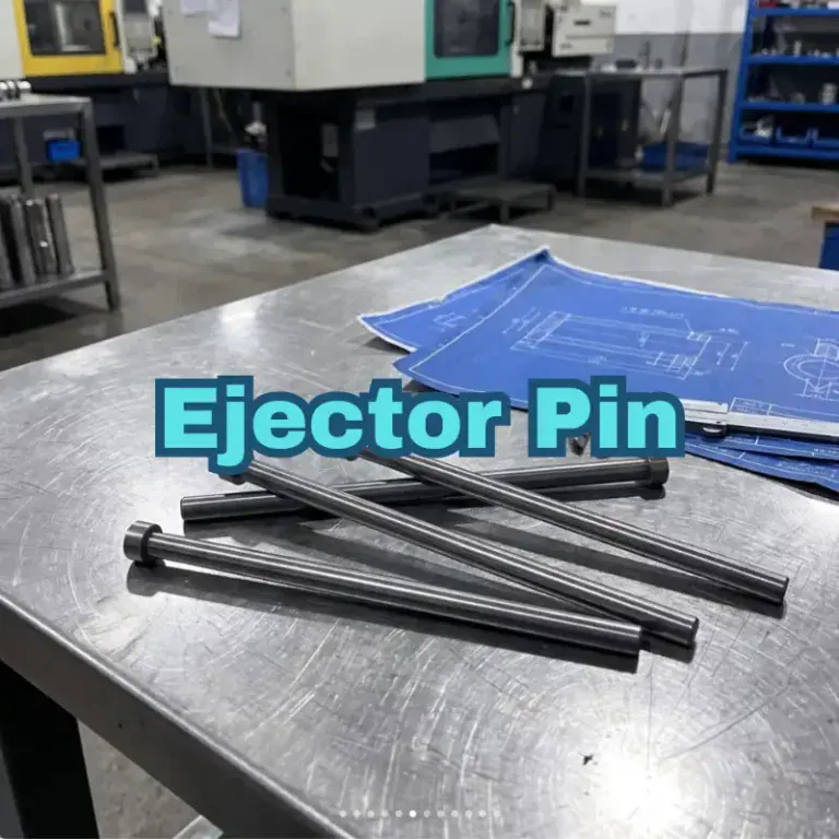
An ejector pin is a hardened mold component that pushes a cooled plastic part away from the mold core after the mold opens. It normally moves with an ejector plate and transfers mechanical force directly to selected areas of the molded part.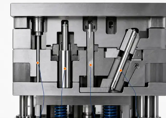
What Ejector Pins Do In Injection Molding
During injection molding, molten plastic fills the cavity and cools around the mold core. As the material shrinks, it often holds tightly to the core side.
Ejector pins apply a controlled pushing force to release the molded part after the mold opens. Several pins are normally distributed across the part so the force is shared instead of concentrated at one point.
Good ejection should remove the part smoothly while maintaining geometry and surface quality. Poor ejection can cause deformation, stress whitening, cracks, scratches, or visible pin marks.
Where Ejector Pins Are Located In An Injection Mold
Ejector pins are usually installed on the moving half, or core side, of an injection mold because the molded part is generally designed to remain on that side after mold opening.
The rear ends of the pins are held by the ejector plate system. Their front ends pass through accurately machined holes and contact the molded part.
The pin locations must be coordinated with cooling channels, inserts, slides, lifters, core pins, and other mold components. A suitable contact point on the plastic part is not always a suitable location inside the mold structure.
Why Mold Ejection Affects Part Quality
The part is still relatively warm when ejection occurs, so it may not yet have reached full stiffness.
If ejection force is too high or concentrated over too small an area, local deformation can occur. Thin walls can bend, bosses can crack, and cosmetic surfaces may show round pin impressions.
Reliable mold ejection therefore depends on both the ejector system and the molded part design. Draft angle, shrinkage, texture, wall thickness, ribs, and core depth all influence how difficult the part is to release.
How Does An Ejector Pin Work?
The ejector pin operates near the end of the molding cycle. After filling, packing, cooling, and mold opening, the ejector mechanism moves forward, pushes the part off the core, and then returns before the next molding cycle begins.
Mold Filling And Cooling
Molten resin first enters the mold cavity under pressure and fills the available geometry.
During packing and cooling, the plastic begins to solidify and shrink. Shrinkage can make the component grip core surfaces tightly, particularly around deep ribs, bosses, textured surfaces, and vertical walls.
The amount of retention depends on material shrinkage, mold finish, draft, part depth, and cooling conditions.
Mold Opening And Part Retention On The Core Side
Once the part has cooled sufficiently, the mold opens along the parting line.
The mold is normally designed so the component remains on the moving core side rather than staying inside the cavity side. This allows the ejector system to push the part forward.
If the part remains on the wrong side, the molding process can become unstable and may require different draft, surface treatment, geometry, or mold-release strategies.
Ejector Plate Movement And Pin Extension
After the mold reaches the required open position, the machine activates the ejector mechanism.
The ejector plate moves forward, carrying the ejector pins with it. The pin faces contact the molded part and transfer force into the plastic.
All pins should advance in a controlled relationship. Uneven pin movement or poor support can tilt the part, concentrate stress, or jam the ejector system.
Part Release And Ejector Pin Return
Once the part separates from the core, it falls or is removed by a robot or operator.
The ejector plate then returns to its original position, pulling the pins back until their faces become flush with the core or other designed surface.
Full return is critical. If an ejector pin remains extended when the mold closes, it can damage the cavity, core, or pin itself.
What Are The Main Types Of Ejector Pins?
Ejector pins are available in several constructions and hardness conditions. The correct type depends on temperature, wear, pin diameter, unsupported length, molding material, cycle rate, and the geometry of the area being ejected.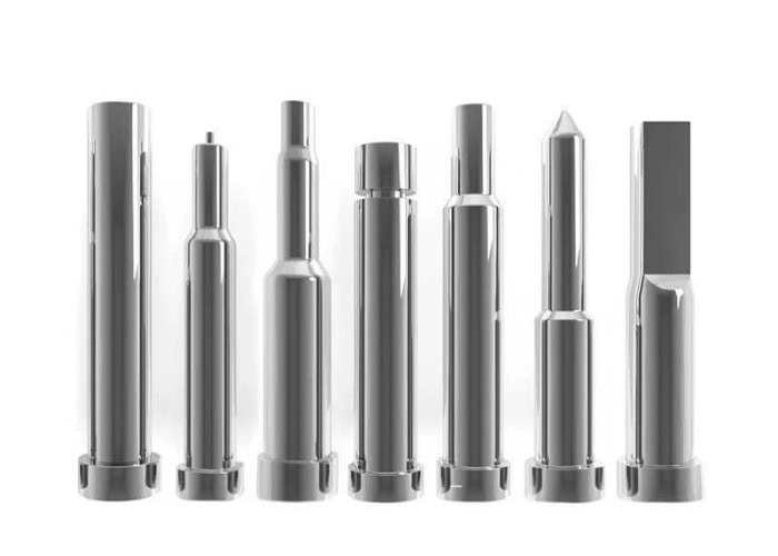
Through-Hardened Ejector Pins
Through-hardened pins are hardened across most or all of their cross-section.
They offer good strength and resistance to bending, which makes them useful in demanding applications where mechanical loading is significant.
Because the entire section is hardened, care is required when machining or modifying the pin. Excessive hardness can also reduce toughness if the material and heat treatment are not suitable.
Nitrided And Case-Hardened Ejector Pins
Nitrided or case-hardened ejector pins use a hard wear-resistant outer surface with a comparatively tougher core.
The hard surface reduces sliding wear as the pin repeatedly moves through the mold plate or guide bore.
This combination is common in injection molds because the pin requires both surface wear resistance and enough core toughness to resist breakage.
Shoulder Ejector Pins
Shoulder ejector pins have a larger supporting diameter behind a smaller working section.
The shoulder provides additional rigidity and reduces the unsupported length of the narrow tip.
These pins are useful when the contact area must be small but a fully small-diameter pin would be too flexible or vulnerable to buckling.
Flat Ejector Pins And Ejector Blades
Flat ejector pins, often called ejector blades, use a rectangular or blade-shaped section instead of a round pin.
They are useful for narrow ribs, thin slots, and other areas where a conventional round pin cannot provide enough contact area.
Because their cross-section is thin, blade guidance and orientation are important. Poorly supported blades can bend or wear more quickly.
Custom Ejector Pins For Special Mold Features
Standard ejector pins cover many applications, but some molds require custom diameters, shoulders, heads, lengths, flats, or shaped contact faces.
Custom pins can improve support or match unusual molded geometry.
However, special components increase manufacturing and replacement cost, so customization should solve a clear mechanical or part-quality problem.
Ejector Pins Vs. Other Mold Ejection Methods
Round ejector pins are the most common ejection solution, but they are not always the best choice. Ejector sleeves, blades, blocks, and stripper plates can distribute force more effectively when part geometry does not provide suitable pin contact areas.
Ejector Sleeves For Bosses And Cylindrical Features
Ejector sleeves are hollow cylindrical ejectors that move around a core pin.
They are especially useful for cylindrical bosses, tubular features, and parts that need ejection force distributed around a central core.
Because an ejector sleeve provides a larger annular contact area than a small round pin, it can reduce local stress on the molded feature.
Ejector Blades For Ribs And Narrow Areas
Ejector blades are well suited to narrow ribs or thin rectangular features.
A blade can provide a longer contact area along the rib while fitting into a narrow space that cannot accept a large round pin.
The design must still provide sufficient blade support because a thin blade can bend under excessive load.
Ejector Blocks For Larger Contact Areas
Ejector blocks contact a larger area of the molded part than pins or blades.
They are useful when high ejection force must be transferred without creating severe local pressure.
Larger contact areas can reduce marks and deformation, but the block requires more mold space and more complex machining.
Stripper Plates For Thin-Walled And Circular Parts
Stripper plates eject the part around a broad perimeter instead of pushing at individual points.
They are commonly used for caps, containers, rings, and thin-walled cylindrical components.
Because the load is distributed over a large area, stripper plates can reduce localized deformation where individual ejector pins would leave unacceptable marks.
How To Choose The Right Ejection Method
The ejection method should match the part geometry, expected release force, appearance requirements, and available mold space.
Round pins are economical and easy to replace. Sleeves suit bosses, blades suit narrow ribs, blocks increase contact area, and stripper plates provide broad uniform ejection.
Many molds use more than one method when different areas of the part require different types of support.
How Should Ejector Pins Be Positioned In A Mold?
Ejector pin placement should follow the actual resistance to mold release. Pins need to distribute force through strong areas of the part while avoiding cosmetic surfaces, fragile walls, and conflicts with other mold components.
Place Pins Where Ejection Resistance Is Highest
Deep cores, tall ribs, bosses, textured surfaces, and areas with limited draft often create high release resistance.
These regions usually need stronger ejection support than shallow, open geometry.
Placing pins near high-resistance zones reduces the distance over which the plastic must transfer ejection force and helps prevent bending.
Distribute Ejection Force Evenly
Using many pins is not automatically better. The objective is balanced ejection.
If most pins are concentrated on one side, the part can rotate, bend, or jam during release.
A balanced pattern allows the component to leave the core approximately parallel to the mold-opening direction.
Position Pins On Ribs, Bosses, And Stronger Areas
Ribs, thicker sections, and supported bosses often provide stronger surfaces for transmitting ejector force.
Placing pins on these areas can reduce local indentation compared with pushing against thin unsupported walls.
However, the exact location still depends on geometry. A poorly supported boss can crack if excessive force is applied directly beneath it.
Avoid Thin Walls And Critical Cosmetic Surfaces
Thin sections are easily deformed while the plastic remains warm.
Likewise, ejector pin marks may be unacceptable on Class-A or other visible surfaces.
Where possible, ejectors should be placed on hidden faces, internal ribs, or areas that will later be covered by another component.
Consider Cooling Channels, Inserts, And Slides
The mold interior places practical limits on pin location.
Cooling channels, screws, inserts, slides, lifters, core pins, and support pillars may already occupy the space behind an ideal ejection point.
Ejector layout therefore needs to be developed together with the overall mold design rather than added after every other system is complete.
How Do You Determine Ejector Pin Size And Quantity?
Ejector pin diameter and quantity should provide enough total contact area and compressive capacity to overcome release resistance without causing excessive local pressure, buckling, or part deformation.
Pin Diameter And Contact Area
A larger ejector pin provides more contact area.
For the same total ejection force, increasing contact area reduces the local pressure applied to the plastic surface.
However, large pins require more mold space and may interfere with other components. The correct diameter balances part strength, available area, and structural requirements inside the mold.
Number Of Pins And Total Ejection Force
Total ejection force should be distributed among enough pins to prevent any single location from carrying excessive load.
Parts with large surface area, deep cores, or limited draft generally require more ejection support.
Pin count should therefore follow actual release resistance rather than a simple rule based only on overall part dimensions.
Unsupported Length And Buckling Risk
Long, slender ejector pins can buckle under compression.
The risk increases as pin diameter decreases and unsupported length increases.
Small-diameter pins may therefore require improved guidance, shorter unsupported sections, or shoulder designs that provide a larger supporting diameter.
Pin Length And Ejection Stroke
Pins must be long enough to reach the molded surface from the ejector plate while maintaining the required support and installation geometry.
Ejection stroke must also be sufficient to separate the component completely from the core.
Excessive stroke adds unnecessary movement and may increase the risk of pin deflection, while insufficient stroke can leave the part partially trapped.
When To Use Small-Diameter Or Shoulder Pins
Small pins are sometimes unavoidable when ejecting narrow features.
If a small working diameter is required, a shoulder ejector pin can improve rigidity by limiting the length of the reduced section.
Designers should avoid using long, unsupported small pins when a larger supported section can be incorporated.
What Materials Are Used For Ejector Pins?
Ejector pin materials need to combine strength, wear resistance, toughness, dimensional stability, and surface quality. The best material depends on mold temperature, resin type, production volume, corrosion risk, and expected maintenance interval.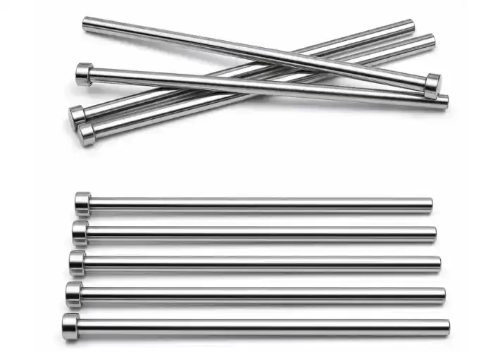
H13 Tool Steel
H13 is widely used in mold tooling because it combines toughness, hot strength, and wear resistance.
It is particularly useful in molds that experience elevated temperatures or repeated thermal cycling.
Heat treatment and finishing quality strongly influence actual ejector pin performance, so material grade alone does not determine service life.
High-Speed And Hardened Tool Steels
High-speed and other hardened tool steels can provide greater wear resistance or strength for demanding applications.
They may be selected for high-cycle molds, abrasive molding compounds, or small pins subjected to significant mechanical loading.
Higher hardness should still be balanced with toughness because an overly brittle pin can fracture instead of bending.
Stainless Steel Ejector Pins
Stainless ejector pins may be used where corrosion resistance is particularly important.
This can include molds exposed to humid environments or corrosive gases released by certain plastic materials.
The selected stainless grade must still provide sufficient hardness and wear resistance for repeated sliding contact.
Heat Treatment And Nitriding
Heat treatment increases hardness and mechanical strength, while nitriding can create a hard surface layer that improves wear resistance.
The treatment must be controlled to avoid distortion because ejector pins rely on tight dimensional and straightness requirements.
Poorly controlled heat treatment can create more problems than the additional hardness solves.
Surface Finish And Wear Resistance
The sliding surface of an ejector pin should be smooth enough to reduce friction and wear.
Rough surfaces can damage the mating bore and increase the risk of seizure.
A consistent finish also supports reliable movement over repeated molding cycles.
What Causes Ejector Pin Marks And Part Deformation?
Ejector pin marks are usually caused by excessive local pressure, insufficient cooling, poor placement, low draft, or weak part geometry. The solution is rarely just changing the pin,the full relationship between the molded part and ejection system should be reviewed.
Excessive Ejection Force
High release resistance requires greater force.
If this force is transferred through too few or too-small pins, contact pressure rises and the pin face can leave a visible impression.
Increasing draft, improving surface release, or increasing ejector contact area can reduce the required local pressure.
Poor Pin Placement And Uneven Load Distribution
A pin located far from high-resistance areas may bend the part before it releases.
Uneven pin spacing can also cause one side to move before the other.
Better force distribution often improves both cosmetic quality and ejection stability.
Insufficient Draft Angle
Low draft increases friction between the molded part and the core.
Textured surfaces may require even more draft because the material must release from the surface texture during ejection.
Increasing draft can significantly reduce ejection force and reduce the chance of pin marks.
Early Ejection And Inadequate Cooling
A part that is still too hot is softer and more vulnerable to deformation.
If ejection starts before enough stiffness has developed, pin faces can sink into the plastic or distort nearby walls.
Longer cooling can improve ejection quality, although cycle-time impact must also be considered.
Thin Walls And Soft Plastic Materials
Thin sections provide less resistance to local pressure.
Soft or flexible materials can also deform easily around ejector contact points.
In these cases, larger pins, more pins, ejector sleeves, blocks, or stripper systems may provide better support.
How To Reduce Pin Marks And Ejection Damage
The first step is reducing unnecessary release resistance through adequate draft, correct mold finish, and appropriate cooling.
Next, distribute force over larger or stronger areas through better pin placement and sufficient contact area.
Where appearance is critical, pin marks should be moved to hidden surfaces or replaced with a different ejection method.
What Are Common Ejector Pin Failures?
Ejector pins can bend, break, seize, wear, or fail to return correctly. Most failures are related to excessive load, insufficient guidance, poor clearance, contamination, misalignment, or inadequate maintenance.
Bent Ejector Pins
Slender pins can bend when compressive load exceeds their stability.
Misalignment also creates side loading, which increases bending risk even when the total ejection force is not especially high.
Shorter unsupported length, larger diameter, improved guidance, or shoulder pins can help.
Broken Ejector Pins
Pins may fracture after repeated bending, impact, fatigue, or excessive loading.
Hard but brittle pins can be particularly sensitive to shock.
If breakage repeats in the same position, the root cause should be corrected rather than simply installing another identical pin.
Pin Seizure And Excessive Friction
Poor clearance, contamination, corrosion, or inadequate lubrication can cause the pin to drag or seize in its bore.
A seized pin can damage the ejector plate, bend the pin, or prevent full mold closure.
Pin straightness, surface condition, and bore alignment should all be checked when friction increases.
Wear Between The Pin And Ejector Hole
Repeated sliding gradually wears both surfaces.
Excessive clearance can allow plastic flash to enter the gap or cause the pin to move laterally.
Wear rates increase when abrasive resin, contamination, or poor surface finish is present.
Poor Return And Ejector Plate Problems
The ejector system must return fully before mold closing.
Broken return components, contamination, plate misalignment, or a stuck pin can prevent complete retraction.
Machine interlocks and ejector return sensors can reduce risk, but mechanical inspection remains necessary.
How To Design And Select A Reliable Ejector Pin System
A reliable ejector system matches pin type, diameter, length, material, location, and contact area to the molded part and expected release load. Design should balance reliable ejection, cosmetic quality, mold life, maintenance, and manufacturing cost.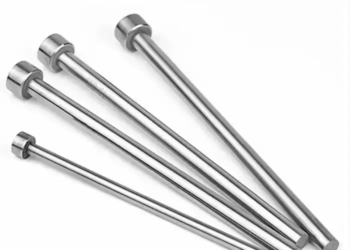
Match Pin Type To Part Geometry And Plastic Material
Round pins suit many general surfaces.
Sleeves are better around bosses, while blades work well on ribs and narrow features.
Plastic stiffness and shrinkage also matter because a rigid engineering resin may transfer ejection force differently from a soft elastomeric material.
Match Diameter And Length To Ejection Load
The pin must provide enough contact area and compressive stability.
A pin that is too small may mark the part or buckle. A pin that is unnecessarily large may occupy valuable mold space.
Length should provide the required stroke without creating excessive unsupported slenderness.
Balance Part Appearance With Ejection Reliability
Cosmetic requirements should be established early.
If ejector marks are unacceptable on one side of the part, the mold must provide usable alternatives on hidden areas.
Trying to relocate pins after the mold is already designed may conflict with cooling lines, slides, or inserts.
Provide Proper Clearance, Guidance, And Lubrication
The pin must slide freely but without excessive looseness.
Clearance should account for operating temperature, pin material, mold material, and production conditions.
Proper guidance reduces side loading, while appropriate lubrication helps reduce friction and wear where the mold design permits it.
Choose Between Standard And Custom Ejector Pins
Standard pins are economical, easy to source, and easy to replace.
Custom ejector pins are justified when geometry, size, shoulder design, contact shape, temperature, or wear requirements cannot be met with standard components.
Whenever possible, maintenance and replacement availability should be considered before specifying a special design.
Consider Mold Life, Production Cycles, And Maintenance Cost
A prototype mold and a high-volume production mold do not need identical ejector systems.
High-cycle molds benefit from stronger materials, controlled wear surfaces, replaceable components, and easier maintenance access.
The lowest initial-cost pin is not necessarily the lowest-cost choice over the complete mold life.
How To Maintain Ejector Pins And The Ejection System
Preventive maintenance keeps ejector pins moving freely and reduces the chance of sudden mold damage. Inspection should focus on wear, straightness, surface condition, clearance, lubrication, and full ejector-plate movement.
Inspect Pins For Wear, Bending, And Surface Damage
Pins should be checked for scoring, discoloration, bending, mushrooming, and uneven wear.
One-sided wear often indicates misalignment or side loading rather than normal service.
Damaged pins should be replaced before they begin to damage the surrounding mold bore.
Check Pin Clearance And Ejector Plate Movement
The ejector plate should move smoothly without binding.
Pins should extend and return together unless the mold intentionally uses staged ejection.
Increasing clearance, irregular movement, or scraping may indicate wear or plate misalignment.
Maintain Proper Lubrication
Lubrication reduces friction between moving mold components.
However, excess lubricant can attract contamination or migrate into areas where it affects molded part quality.
The type and amount should follow the mold design and operating conditions rather than a universal rule.
Replace Worn Pins Before They Damage The Mold
Ejector pins are usually less expensive to replace than damaged mold plates, inserts, or cavities.
Replacing a worn pin early prevents excessive clearance, seizure, and secondary damage.
Maintenance records can also reveal repeated failures that indicate a deeper design or alignment problem.
FAQs
Do Ejector Pins Always Leave Marks On Injection Molded Parts?
Most ejector pins can leave some evidence of contact, but the mark can often be minimized through correct pin size, placement, cooling, draft, and ejection-force distribution. Cosmetic parts usually require ejectors to be placed on hidden or noncritical surfaces.
When Should Ejector Sleeves Be Used Instead Of Ejector Pins?
Ejector sleeves are especially useful around cylindrical bosses or core pins where force needs to be distributed around a circular feature. They provide a larger contact area than a single small pin and can reduce localized deformation.
Why Do Small Ejector Pins Bend Or Break?
Small pins have lower resistance to buckling, particularly when their unsupported length is large. Excessive ejection force, side loading, poor guidance, misalignment, or repeated fatigue can further increase the risk of bending and breakage.
How Many Ejector Pins Does An Injection Mold Need?
There is no fixed number. Pin quantity depends on part size, release resistance, geometry, draft, material, contact area, and allowable surface pressure. The goal is to distribute enough ejection force evenly without damaging the molded part.
Conclusion
A reliable ejector pin system must do more than simply push a molded part out of the tool. Pin type, size, quantity, placement, material, guidance, cooling, and release resistance all influence whether ejection is smooth and repeatable. Good design distributes force through strong areas, limits visible marks, reduces deformation, and prevents pin bending, wear, and seizure throughout the mold’s service life.
At TiRapid, we provide precision CNC machining and manufacturing services for custom mold components, ejector pins, sleeves, inserts, and other precision tooling parts. Our team combines material selection, controlled machining, dimensional inspection, and practical manufacturing support to help produce reliable components for mold development, maintenance, and production.