A compressor impeller is a high-speed rotating component that transfers mechanical energy to gas in a centrifugal compressor. Its blades accelerate the gas through carefully designed flow passages, helping the compressor generate the required pressure. Blade geometry, material properties, and manufacturing accuracy directly affect efficiency, stability, and service life.
This guide explains how a compressor impeller works, the main impeller types, important design features, and factors affecting performance. It also covers material selection, CNC machining, quality inspection, industrial applications, and maintenance considerations to help engineers understand and manufacture reliable compressor components.
What Is a Compressor Impeller?
A compressor impeller is the rotating aerodynamic component of a centrifugal compressor that transfers energy from the drive shaft to incoming gas. It consists of a central hub and specially shaped blades that accelerate gas toward the outer diameter, creating the energy needed for pressure generation within the compressor stage.
To answer the common question, what is an impeller, it is useful to distinguish the rotating part from the complete compression system. The impeller adds energy to the gas, while stationary components such as the diffuser and volute help convert and collect that energy as useful pressure.
Unlike screw or reciprocating compressors, which compress gas through positive displacement, centrifugal compressors use a continuous high-speed flow process. Their main components include the impeller, diffuser, casing, shaft, bearings, seals, and inlet system.
The impeller is particularly important because small changes in blade geometry, surface condition, or rotational accuracy can influence aerodynamic losses and mechanical reliability. Its design must therefore account for both fluid behavior and the demands of high-speed rotation.
How Does a Compressor Impeller Work?
A compressor impeller works by using rotating blades to transfer mechanical energy to gas and accelerate it outward. The gas gains velocity and total pressure inside the impeller, then enters a stationary diffuser, where part of its kinetic energy is converted into additional static pressure.
The Role of the Impeller in a Centrifugal Compressor
The impeller provides the main energy input to the gas in a centrifugal compressor stage. It is connected to a rotating shaft driven by an electric motor, turbine, or other power source. As the shaft turns, the blades transfer mechanical energy to the flowing gas.
The compressor is designed around specific operating conditions, including inlet pressure, temperature, gas composition, flow rate, and rotational speed. These conditions determine the required aerodynamic geometry and help establish the mechanical loads acting on the impeller.
An appropriately designed impeller delivers the energy needed for compression while limiting unnecessary flow losses. However, the impeller cannot be evaluated independently of the diffuser and surrounding casing because the complete stage determines the final pressure rise and efficiency.
How the Impeller Accelerates Gas
Gas enters the compressor through the inlet and approaches the central opening of the impeller, commonly called the eye. Rotating blades guide the gas through curved passages toward the outer diameter, increasing its energy and changing its velocity direction.
The impeller’s outer diameter and rotational speed determine its tip speed, a key parameter in energy transfer. For example, an impeller with a 200 mm outer diameter rotating at 30,000 RPM has a calculated tip speed of approximately 314 m/s.
This value is an illustrative calculation, not a universal operating requirement. Actual gas velocity depends on the blade exit angle, flow conditions, slip, and compressor design. Engineers must also check stresses and aerodynamic limitations before selecting a rotational speed.
How the Diffuser and Volute Increase Pressure
The diffuser is a stationary component located downstream of the impeller. It reduces gas velocity in a controlled manner, recovering part of the kinetic energy as static pressure. This is an essential part of the centrifugal compressor impeller and diffuser relationship.
After leaving the diffuser, gas moves into a volute or another collection passage. In a single-stage compressor, the volute collects flow around the circumference and directs it toward the outlet. In multistage machines, return passages may guide the gas toward the next impeller.
A centrifugal compressor diagram typically shows the following flow sequence:
- Inlet:Gas enters through the compressor inlet.
- Impeller:Rotating blades add energy and accelerate the gas.
- Diffuser:Gas slows down and static pressure increases.
- Volute or Return Channel:Gas is collected and directed toward the outlet or next stage.
The impeller, diffuser, and downstream passages must be designed together to achieve the required pressure rise without excessive aerodynamic losses.
What Are the Types of Compressor Impellers?
The main centrifugal compressor impeller types can be classified by blade exit direction into backward-curved, forward-curved, and radial-blade designs. These configurations influence energy transfer, aerodynamic efficiency, pressure characteristics, and operating stability.
Understanding the different types of impeller is important because no single blade configuration is ideal for every operating condition. Blade orientation must match the compressor’s aerodynamic requirements and mechanical limits.
Backward-Curved Impellers
Backward-curved impellers have blades that lean opposite to the direction of rotation at the outlet. This design is widely used in modern centrifugal compressors because it can provide high aerodynamic efficiency and favorable operating characteristics.
The backward-swept blade shape helps control discharge velocity and reduces the pressure recovery burden on the diffuser. Depending on the overall compressor design, it can also contribute to a practical operating range and improved resistance to flow instability.
The main engineering challenge is achieving the required pressure rise while controlling blade stress, passage geometry, and manufacturing complexity. Backward-curved designs often involve complex three-dimensional surfaces that require precise machining and aerodynamic verification.
Forward-Curved Impellers
Forward-curved impellers have blades that lean in the same direction as rotation at the outlet. This configuration can produce a higher theoretical energy transfer at a given tip speed than a backward-curved design under comparable idealized conditions.
However, forward-curved blades often generate higher discharge velocities, increasing the amount of diffusion required downstream. This can introduce additional aerodynamic losses and make it more difficult to achieve high compressor-stage efficiency.
Forward-curved designs are relatively uncommon in modern high-efficiency centrifugal gas compressors. They may be considered for specific aerodynamic requirements, but their benefits must be evaluated against power consumption, diffuser performance, and operating stability.
Radial-Blade Impellers
Radial-blade impellers have blade exits oriented approximately in the radial direction rather than leaning forward or backward. Their outlet geometry provides a different balance of theoretical work input, aerodynamic behavior, and structural loading.
Radial designs can offer useful mechanical characteristics in applications involving high rotational stresses. However, their performance still depends on inlet geometry, blade thickness, passage design, and the behavior of the downstream diffuser.
These impellers are not automatically stronger or more efficient in every application. Engineers must evaluate material stress limits, aerodynamic requirements, blade geometry, and operating speed before deciding whether a radial configuration is suitable.
Comparison of Compressor Impeller Types
The following table summarizes the general characteristics of the three blade configurations.
| Impeller Type | Blade Direction | General Characteristics | Main Consideration |
| Backward-Curved | Opposite rotation | Generally high efficiency and favorable operating range | Complex aerodynamic design |
| Forward-Curved | With rotation | Potentially higher ideal work input at a given tip speed | Higher discharge velocity and losses |
| Radial-Blade | Radial at outlet | Useful mechanical and aerodynamic characteristics | Efficiency and stress tradeoffs |
These are broad design tendencies rather than fixed performance rankings. Actual results depend on the complete compressor stage, including inlet geometry, blade design, diffuser configuration, and operating conditions.
Key Design Features of Compressor Impellers
Compressor impeller design focuses on blade geometry, flow passage dimensions, rotational speed, clearances, and structural configuration. Each feature influences how effectively energy is transferred to the gas and whether the component can operate reliably under high centrifugal forces.

Blade Geometry and Flow Passages
The geometry of each impeller blade determines how gas enters, accelerates, and leaves the rotating passage. Important parameters include blade inlet angle, outlet angle, blade height, thickness, curvature, and the number of full or splitter blades.
Poorly matched blade angles can cause unfavorable incidence, flow separation, and additional aerodynamic losses. Designers therefore use aerodynamic calculations and computational fluid dynamics to understand flow distribution before finalizing the geometry.
From a manufacturing perspective, highly curved blades and narrow passages create additional challenges. Tool accessibility, thin-wall deflection, and surface consistency must be considered early because even a geometrically correct CAD model may be difficult to machine efficiently.
Impeller Diameter, Speed, and Clearances
Impeller diameter and rotational speed strongly influence tip speed and aerodynamic work input. Larger diameters or higher speeds can increase energy transfer, but they also affect centrifugal stress, rotor dynamics, and the mechanical safety margin.
Tip clearance is the gap between an unshrouded impeller blade and the surrounding stationary housing. Excessive clearance can increase leakage and flow losses, while insufficient clearance creates a risk of contact during thermal expansion or rotor movement.
Designers must also account for shaft fit, hub dimensions, and thermal behavior. These features determine how the impeller is mounted and how reliably it maintains its intended position during startup, normal operation, and changing temperature conditions.
Open and Shrouded Impeller Designs
Open or unshrouded impellers have blade passages that are not enclosed by a front cover. This arrangement provides greater access to blade surfaces and is commonly used when aerodynamic, weight, or manufacturing requirements favor an unshrouded configuration.
Closed or shrouded impellers use a cover to enclose the blade passages. The shroud changes leakage behavior, mechanical loading, and manufacturing accessibility. Depending on the design, a closed impeller may be assembled, brazed, welded, cast, or manufactured using another suitable process.
Open and closed configurations represent a structural classification, not the same classification as backward-curved or radial blades. Both blade orientation and shroud arrangement must be specified when selecting an impeller for a particular compressor.
What Factors Affect Compressor Impeller Performance?
Compressor impeller performance depends mainly on flow rate, pressure ratio, aerodynamic efficiency, operating speed, and mechanical stability. These variables determine whether the compressor can deliver the required gas pressure efficiently while maintaining reliable operation throughout its intended operating range.
Flow Rate, Pressure Ratio, and Efficiency
Flow rate describes the amount of gas moving through the compressor over time. Pressure ratio compares the compressor’s outlet absolute pressure with its inlet absolute pressure. Together with efficiency, these parameters help engineers evaluate operating performance.
A compressor designed for one flow condition may perform less efficiently when operated far from that point. Blade angles, passage dimensions, diffuser geometry, and gas properties all influence the relationship between flow rate and pressure rise.
For this reason, impeller design typically involves evaluating performance maps across multiple operating conditions. Engineers seek a suitable combination of efficiency, usable flow range, and pressure capability instead of optimizing only a single maximum-pressure condition.
Surge, Vibration, and Mechanical Stability
Surge is a system-level aerodynamic instability that can occur when a compressor cannot maintain stable forward flow. It may produce significant pressure fluctuations and flow reversals, potentially damaging the impeller, bearings, seals, and connected equipment.
Vibration can result from rotor imbalance, misalignment, blade excitation, aerodynamic forces, or other mechanical problems. High-speed operation increases the importance of accurate mass distribution, shaft alignment, and avoiding harmful resonances.
Engineers address these risks through aerodynamic design, rotor-dynamic analysis, proper operating controls, and quality inspection. A balanced impeller alone cannot prevent surge, and an efficient aerodynamic design cannot compensate for serious mechanical defects.
Compressor Impeller Materials and Manufacturing
Compressor impellers are manufactured using CNC machining, casting, forging, or other specialized processes, depending on their geometry, material, and production requirements. Precision CNC machining is particularly suitable for producing complex blade profiles, accurate mounting features, and custom impellers that require tight dimensional control.

Common Materials and Selection Factors
Aluminum alloys are commonly used for lightweight compressor impellers because they offer low density, good machinability, and suitable strength for selected operating conditions. Grades such as 6061 and 7075 may be considered depending on the required mechanical properties. However, operating temperature and fatigue resistance must be evaluated before selecting an alloy.
Stainless steel is often selected for industrial compressor impellers exposed to demanding mechanical loads or corrosive environments. Grades such as 17-4 PH can provide high strength after appropriate heat treatment, while other stainless steels offer different corrosion resistance characteristics. The final selection depends on gas composition, temperature, stress, and service conditions.
Titanium alloys provide a high strength-to-weight ratio and good corrosion resistance, making them suitable for certain high-speed compressor applications. Nickel-based alloys may also be required when elevated temperatures or aggressive environments exceed the capabilities of conventional materials. Engineers must consider fatigue strength, density, thermal expansion, and long-term reliability.
CNC Machining of Compressor Impellers
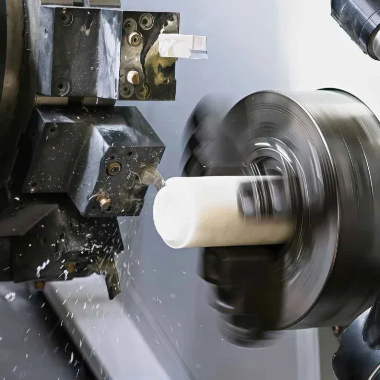
CNC machining is widely used to manufacture precision compressor impellers with complex aerodynamic surfaces and accurate mounting features. The process typically begins with CNC turning to establish the central bore, hub diameter, and reference faces. These features provide stable locating datums for subsequent operations, helping maintain alignment between the impeller blades and rotational axis.
5-axis CNC machining is especially important for manufacturing curved blades and narrow flow passages. Simultaneous multi-axis movement allows the cutting tool to approach complex surfaces from different orientations. This capability improves access to twisted blade profiles and reduces unnecessary repositioning, which helps control geometric errors during custom impeller production.
The machining process generally includes roughing, semi-finishing, and finishing operations. Roughing removes excess material and opens the flow passages, while semi-finishing establishes a consistent machining allowance. Finishing uses carefully programmed toolpaths to produce the required blade geometry, particularly around leading edges, trailing edges, and blade-root transitions.
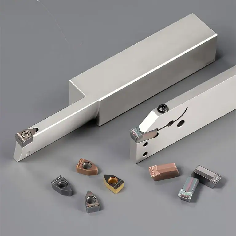
Thin blades and deep channels create additional machining challenges because cutting forces can cause deflection, vibration, or dimensional variation. Engineers must select appropriate cutter geometry, tool length, feed rates, and cutting speeds. CAM simulation, stable fixturing, and controlled tool engagement help reduce collision risks and improve consistency across complex impeller surfaces.
Other Manufacturing Processes for Compressor Impellers
Casting is an alternative manufacturing method for compressor impellers with complex shapes or production requirements that make extensive material removal inefficient. Investment casting can produce near-net-shape components with relatively intricate geometry. However, casting allowances, shrinkage, and internal defects must be considered, and critical surfaces may still require CNC finish machining.
Forging is used when the impeller requires a wrought material structure and suitable mechanical properties under high rotational loads. Forged blanks can provide favorable material integrity when the forging process is properly controlled. Because complex blade passages are generally not formed directly, CNC machining is often necessary to produce the final aerodynamic geometry.
Additive manufacturing offers another option for complicated internal passages that may be difficult to produce with conventional cutting tools. Metal powder bed fusion can create intricate shapes, although surface quality, porosity, residual stress, and dimensional accuracy require careful verification. Heat treatment and secondary machining are often needed before the impeller is ready for service.
Electrical discharge machining may be used for selected features that are difficult to access through conventional milling, provided the material is electrically conductive and a suitable electrode or wire path is available. Some shrouded impellers are also produced by joining separately manufactured components. These methods require careful evaluation of structural integrity, accessibility, and manufacturing cost.
Surface Finish, Tolerances, and Quality Inspection
Surface finish is important because the condition of the impeller blades and flow passages influences aerodynamic losses and local flow behavior. Uneven tool marks, burrs, and surface defects can disturb gas movement, particularly around blade edges. Finishing methods must achieve the specified surface roughness without changing critical aerodynamic geometry.
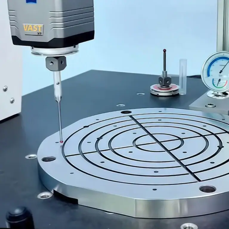
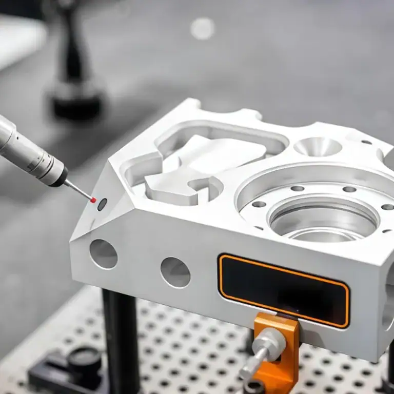
Dimensional tolerances are equally important for maintaining correct assembly and operating clearances. Engineers typically inspect the bore diameter, mounting faces, blade profile, runout, and other functional features. Coordinate measuring machines and optical scanning systems can verify accessible geometry, while specialized inspection methods may be needed for enclosed passages.
Dynamic balancing is essential for many high-speed compressor impellers because uneven mass distribution can increase vibration and bearing loads. The required balance quality depends on rotor design, operating speed, and applicable specifications. Balancing should be performed under the defined component or assembly conditions rather than assuming one universal grade is suitable.
A reliable inspection plan combines material verification, dimensional measurement, surface evaluation, and appropriate rotor checks. Critical features should be identified from the engineering drawing before production begins. Recording inspection results throughout manufacturing helps detect deviations early and reduces the risk of assembly problems or premature component failure.
Common Applications of Compressor Impellers
Compressor impellers are used in centrifugal compression systems that require continuous gas flow and controlled pressure increases. Major application areas include industrial air and gas systems, HVAC and refrigeration equipment, and high-speed turbomachinery such as turbochargers and aerospace compressors.

Industrial Air and Gas Compressors
Industrial centrifugal compressors are widely used to supply compressed air and process gases for manufacturing, energy, and chemical operations. Their impellers must provide the required pressure and flow while maintaining stable performance over the intended operating conditions.
Material compatibility becomes especially important when the compressed gas contains moisture, corrosive compounds, or other contaminants. Mechanical strength, corrosion resistance, and reliable shaft connections must be evaluated alongside aerodynamic efficiency.
For custom industrial impellers, CNC machining supports the accurate production of mounting features and complex blade geometry. Inspection planning must also account for the operating environment and the importance of continuous equipment availability.
HVAC and Refrigeration Systems
Centrifugal compressors are used in large cooling and refrigeration systems where high gas flow rates and efficient continuous operation are important. Their impellers accelerate refrigerant vapor, allowing the compressor stage to raise pressure for the refrigeration cycle.
The design must match the properties of the specific refrigerant and the required temperature and pressure conditions. Efficiency across changing cooling loads is important because actual operating conditions may differ from the nominal design point.
Mechanical reliability also matters in these systems because compressor failures can affect the operation of an entire cooling installation. Appropriate material selection, accurate machining, and inspection help support consistent service performance.
Turbochargers and Aerospace Systems
Turbochargers use high-speed compressor wheels to increase the intake-air pressure supplied to an engine. These components commonly use carefully optimized three-dimensional blade shapes to achieve suitable pressure ratios within compact packaging.
Aerospace compressors face demanding requirements involving weight, temperature, rotational speed, and mechanical reliability. Depending on the application, engineers may use centrifugal, axial, or mixed-flow compressor architectures rather than a single universal impeller design.
For both applications, precision manufacturing is important because blade geometry and rotor mass distribution affect performance. Material certification, process control, and verification requirements must reflect the operating conditions and applicable specifications.
Common Compressor Impeller Problems and Maintenance
Common compressor impeller problems include erosion, corrosion, fouling, blade damage, and rotor imbalance. These conditions can alter aerodynamic surfaces, reduce compression efficiency, increase vibration, and shorten component life if they are not identified and corrected in time.
Maintenance requirements depend on operating conditions, gas cleanliness, component design, and manufacturer recommendations. Understanding the failure mechanism is more useful than relying on a single inspection interval for every compressor.
Erosion, Corrosion, and Fouling
Erosion occurs when particles or liquid droplets damage blade surfaces during operation. Repeated impact can change the leading-edge shape and increase surface roughness, reducing the accuracy of the original aerodynamic profile.
Corrosion results from interaction between the material and its operating environment. Moisture, chemicals, and aggressive process gases can damage susceptible surfaces, while fouling deposits can gradually restrict flow passages and disturb gas distribution.
Preventive measures include appropriate filtration, material selection, protective treatment where suitable, and condition-based cleaning. Engineers should also investigate the source of contamination before replacing a damaged impeller.
Impeller Wear, Imbalance, and Blade Damage
Impeller damage may result from foreign-object impact, fatigue, contact with surrounding components, or excessive operational loading. Cracks near blade roots and other highly stressed regions can be particularly serious because repeated cyclic loads may promote crack growth.
Uneven material loss or deposits can change the rotor’s mass distribution and increase vibration. However, increased vibration does not always mean the impeller itself is damaged, bearings, couplings, shaft alignment, and other components may contribute.
A proper assessment therefore combines visual inspection, dimensional checks, vibration analysis, and suitable nondestructive testing when required. Replacement or repair decisions should be based on the severity of the defect and the manufacturer’s approved criteria.
Inspection and Preventive Maintenance
Preventive maintenance begins with monitoring operating conditions such as vibration, pressure, flow, and temperature. Unexpected changes can indicate fouling, aerodynamic instability, mechanical wear, or other problems requiring investigation.
During planned inspection, engineers examine blade surfaces, leading and trailing edges, the hub, mounting interfaces, and accessible flow passages. Cleaning methods must avoid changing critical blade geometry or removing protective coatings unintentionally.
After significant repairs or material removal, dimensional inspection and balancing may be necessary before the component returns to service. Maintenance procedures should follow the compressor manufacturer’s instructions and any relevant safety requirements.
FAQs
Can A Closed Compressor Impeller Be Machined From A Solid Block?
Closed compressor impellers can sometimes be machined from solid material, but fully enclosed curved passages may prevent conventional cutting tools from reaching every surface. 5-axis CNC machining is effective for accessible blade geometry, while enclosed passages may require electrical discharge machining, specialized tooling, or alternative construction. Casting, additive manufacturing, or a machined impeller with a separately joined shroud may be more practical. The choice depends on passage geometry, material, required tolerances, production volume, and inspection accessibility.
What Tolerance Should Engineers Specify For A Compressor Impeller?
There is no universal tolerance suitable for every compressor impeller. Critical requirements usually include bore size, mounting-face runout, concentricity, and blade profile accuracy. Some precision projects may specify dimensional tolerances of ±0.02 mm on selected features, but this is an example rather than a standard requirement. Engineers should identify functional datums, evaluate thermal and rotational effects, and specify inspection methods. Applying excessively tight tolerances to noncritical surfaces can increase machining cost without improving compressor performance.
How Is Balance Quality Specified For High-Speed Compressor Impellers?
Balance quality is specified according to rotor design, operating speed, permissible vibration, and applicable standards. ISO 21940-11 defines procedures and residual unbalance tolerances for rotors with rigid behavior. A balance quality grade such as G2.5 may be used in certain applications, but it is not automatically appropriate for every compressor. Engineers must also consider balancing planes, assembly configuration, correction methods, and the relationship between component balancing and final rotor-system performance.
When Should Engineers Choose Aluminum Instead Of Titanium?
Aluminum may be preferred when low weight, machinability, and manufacturing cost are major priorities and the operating conditions permit its use. Typical aluminum alloys have a density near 2.7 g/cm³, compared with approximately 4.4–4.5 g/cm³ for common titanium alloys. Titanium can provide higher specific strength and better performance in certain demanding environments, but it is usually more expensive to machine. Final selection must account for temperature, fatigue, corrosion, allowable stress, and project requirements.
Can A Damaged Compressor Impeller Be Repaired Instead Of Replaced?
Repair may be possible for limited surface defects, deposits, or approved dimensional corrections, but the decision depends on defect location, material, and operating speed. Cracks in highly stressed blade regions or serious structural damage may require replacement. Welding, polishing, or material removal should never be performed without an approved engineering procedure. Following repair, the impeller may require dimensional inspection, nondestructive testing, and rebalancing. For high-speed critical equipment, manufacturer approval is particularly important.
Conclusion
A compressor impeller is essential to the performance and reliability of a centrifugal compressor. Its blade configuration, aerodynamic geometry, material properties, and manufacturing accuracy all influence pressure generation and operating efficiency. Backward-curved, forward-curved, and radial-blade impellers serve different design requirements, while open and shrouded structures introduce additional mechanical considerations. Understanding these factors helps engineers select appropriate designs, reduce manufacturing risks, and achieve reliable performance in demanding compressor applications.
At TiRapid, we provide precision CNC machining and manufacturing services for custom compressor impellers, including multi-axis milling, turning, and dimensional inspection. Our manufacturing approach supports complex blade geometry, accurate assembly features, and reliable custom metal components for demanding industrial applications.