Blade machining produces or refines the airfoil, attachment features, and edges that allow a blade to fit its assembly and interact with the working fluid. The challenge is controlling those features while material removal changes the stiffness of the workpiece. A smooth-looking surface is insufficient if its profile, thickness, or relationship to the root is incorrect.
This guide focuses on machining metallic turbine and compressor blades. It explains how the starting blank and material affect the process, when simultaneous five-axis milling helps, where other processes are needed, and how to define inspection requirements. Engineers and buyers can use these principles to prepare clearer drawings and compare manufacturing proposals.
What Is Blade Machining?
Blade machining is controlled material removal used to create or finish a blade’s aerodynamic and attachment features. It can involve machining an airfoil from solid stock or selectively finishing a cast or forged blank. The required operations depend on the blade design, material, and starting condition.

Machining From Solid Stock And Near-Net Blanks
Machining from solid stock provides a practical route for certain development parts, compressor components, and blade designs whose geometry and material requirements suit that approach. The process establishes the airfoil by removing material around a supported blank.
A near-net blank already contains much of the blade shape. Machining may concentrate on the root, platform, tip, sealing features, and selected airfoil regions rather than generating every surface from scratch. Incoming geometry and machining allowance become important because the blank is not an exact copy of the nominal CAD model.
Many jet engine turbine blades in high-pressure stages rely on investment casting, including directionally solidified or single-crystal routes where specified. Milling a similar external shape from ordinary bar stock does not reproduce that material structure. Complex internal cooling passages can be formed during casting with ceramic cores, followed by machining and other finishing operations.
Individual Blades And Integrated Bladed Parts
An individual blade can be held through its root, temporary features, or an appropriate fixture. A blisk integrates blades with the disk, so neighboring blades restrict cutter access. Impellers also contain closely spaced flow passages, but their geometry and function require their own process planning.
This guide concentrates on individual blades and the machining principles shared with related turbomachinery parts. Turbine blading should be specified by its actual component type rather than treated as one interchangeable family.
How Do Geometry And Materials Shape The Process?
Blade geometry determines access, support, and the relationship between functional surfaces. Material determines cutting behavior and suitable processing routes. Review both together because a toolpath that works on an accessible aluminum demonstration part may be unsuitable for a thin nickel-alloy production blade.
Airfoil, Root, And Edge Requirements
The airfoil changes curvature and section along its span. Pressure and suction surfaces, twist, chord, and thickness distribution must remain consistent with the design. Measuring overall length and width cannot establish whether the intended airfoil has been produced.
The root and platform establish mechanical and geometric relationships with the assembly. Their position relative to the airfoil matters as much as their individual dimensions. Leading and trailing edges also require defined profiles, rather than an instruction to make every edge as sharp as possible.
| Blade Region | Manufacturing Concern | Requirement To Clarify |
| Airfoil surfaces | Changing curvature and cutter contact | Profile, section definition, and surface texture |
| Thin sections | Deflection as stock is removed | Thickness and acceptable inspection condition |
| Root and platform | Attachment fit and datum relationships | Geometry, location, and orientation |
| Leading and trailing edges | Burrs, overcutting, and rounding | Edge thickness, radius, and permitted blending |
| Tip or shroud, where present | Access and relationship to adjacent features | Finished geometry and assembly requirements |
Material Selection And Machinability
The material specification should come from the component’s operating requirements. Titanium alloys are important in many compressor and fan applications, while nickel-based superalloys are associated with hotter turbine regions. Steam turbine blades can use suitable stainless or alloy steels, depending on the design and service conditions.
| Material Family | Relevant Application Context | Machining Consideration |
| Nickel-based superalloys | Hot-section components where the specified alloy and structure are suitable | Heat concentration, work hardening, and tool wear |
| Titanium alloys | Many compressor and fan components | Cutting-zone heat, tool adhesion, and workpiece flexibility |
| Stainless and alloy steels | Appropriate steam turbine and industrial blade designs | Grade, hardness, cutting forces, and tool selection |
| Aluminum alloys | Selected development models and suitable lower-temperature applications | Burr control and deformation of thin sections |
An alloy family alone is not a complete specification. Include the exact grade, stock form, heat-treatment condition, and applicable material requirements. Changing the alloy or blank route may change both machinability and the component’s suitability for service.
How Does The Blade Machining Process Work?
A blade machining plan normally starts with model and drawing review, followed by datum preparation, controlled roughing, semi-finishing, and finishing. The sequence must preserve support while establishing the required relationship between the airfoil and mounting features. A cast blank and a solid billet will not necessarily follow the same route.
Review The Model And Establish References
Check that the computer-aided design (CAD) model and drawing describe the same revision. Identify the controlled airfoil surfaces, section locations, root interfaces, machining boundaries, and features that must remain untouched. Resolve missing edge definitions before programming.
The computer-aided manufacturing (CAM) system translates that product geometry into planned cutting operations. Confirm model units, surface continuity, tool definitions, and remaining stock before generating paths. A clean-looking toolpath preview does not establish that the programmed geometry or machining tolerance matches the drawing.
Plan how manufacturing references relate to inspection datums. A temporary clamping feature may help production without becoming a design datum. Conversely, holding a finished root is useful only if the fixture locates it consistently without damage or distortion.
Fixture design must also preserve access for later operations. A clamp that securely holds the blank may obstruct the platform after the airfoil is finished. If the part must transfer between fixtures, establish a repeatable reference transfer and protect finished contact surfaces. Confirm that the released part, rather than only the clamped shape, satisfies the specified acceptance condition.
For near-net blanks, verify that enough material exists in the intended finishing regions. An incoming shape check can identify misplaced stock or local shortages before expensive machining begins. Moving the blank to improve machining allowance must still preserve the specified relationship to functional features.
Rough Without Losing Support
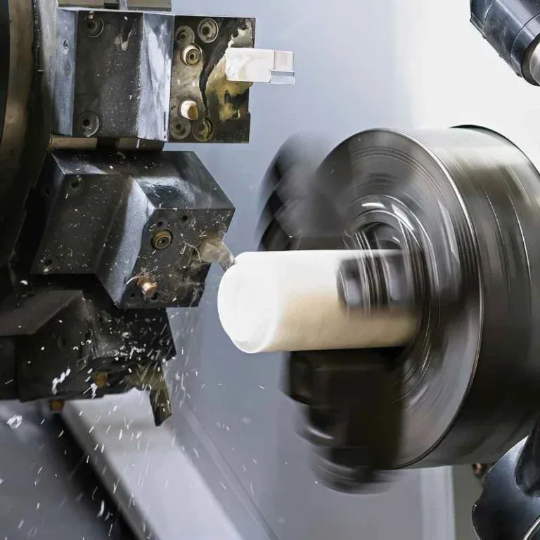
Roughing removes bulk material while retaining enough stock and stiffness for subsequent operations. The objective includes predictable cutter engagement, effective chip evacuation, and a workpiece that remains stable as its cross-section changes.
A sequence that finishes one thin side while leaving heavy stock on the other can create an unfavorable force and stiffness balance. Depending on the design, staged removal from opposing sides or incremental machining along the blade can provide better support.
Do not assume that removing more material early always shortens the complete cycle. Extra vibration, surface damage, or distortion can create additional finishing and inspection work. The useful measure is a reliable finished component, rather than the roughing rate alone.
Semi-Finish For Predictable Final Cuts
Semi-finishing brings the workpiece close to its final shape and establishes a controlled distribution of remaining material. Uniform finishing allowance helps avoid abrupt changes in cutting load across the airfoil.
This stage is also an opportunity to check stock, tool condition, and dimensional trends before the surface becomes difficult to recover. If the blade has moved after unclamping or a previous operation, investigate the cause before applying a blanket tool offset.
Material removal can redistribute residual stresses, while cutting can introduce additional near-surface effects. Semi-finishing does not automatically eliminate these stresses. Any heat treatment or stabilization step must suit the material specification and approved manufacturing route.
Finish The Airfoil And Protect The Edges
Finishing establishes the specified profile and texture through controlled cutter contact. Plan approach, exit, stepover, and transitions so that the tool does not dwell or make abrupt direction changes in sensitive regions.
Leading and trailing edges need particular attention because tool engagement and local stiffness can change quickly. Preserve the specified thickness and radius through both machining and later deburring. A visually clean edge can still be unacceptable if blending removes too much material.
Inspect features that later operations may obscure or alter. For example, checking a surface before coating can support process control, while final acceptance may require additional inspection after coating and edge conditioning.
When Does Blade Machining Need 5-Axis CNC?
Simultaneous five-axis CNC is useful when tool orientation must change continuously to reach and follow a twisted blade surface. Accessible features may be machined with fixed-axis or indexed methods. Select the machine arrangement from geometry, reach, rigidity, and verification needs rather than treating the axis count as a quality guarantee.

Indexed Positioning And Simultaneous Motion
In indexed, or 3+2, machining, rotary positioning establishes an orientation before a fixed-orientation cutting operation. Simultaneous five-axis machining allows the tool orientation relative to the part to change during the cut.
Continuous orientation control can improve access around airfoils and reduce the need for long tools or repeated repositioning. It also introduces machine-motion constraints that must be handled in programming. Rotary travel limits, rapid orientation changes, and available clearance can all affect the practical route.
Fewer setups can help preserve feature relationships, but a five-axis machine does not guarantee that the complete blade can be finished in one clamping. Workholding features may need removal, and specialized operations may require different equipment.
Verify The Complete Machine Motion
Check the cutter, holder, fixture, workpiece, and relevant machine components. A tool tip can follow the intended surface while the holder approaches a platform or the rotary assembly approaches a travel limit.
Simulating the postprocessed numerical control (NC) program helps evaluate the code intended for the actual machine, including motions introduced during postprocessing. The simulation must use representative tool lengths, holders, stock, fixtures, and machine configuration.
Simulation supports planning but does not measure actual cutting forces or prove the finished profile. Setup verification and controlled first-part inspection remain necessary to confirm that the physical process follows the plan.
Which Tools And Toolpaths Suit Blade Surfaces?
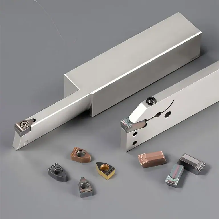
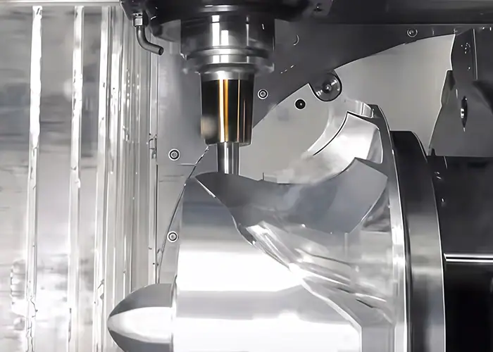
Tool selection should match local curvature, reach, material, and the required surface result. Ball-nose, bull-nose, flank-milling, and circle-segment approaches serve different geometries. A suitable strategy maintains useful cutter contact without excessive deflection, collisions, or uncontrolled changes in engagement.
Match Cutter Contact To Local Geometry
Ball-nose and bull-nose cutters provide flexibility for sculptured surfaces. With a ball-nose tool, contact near the center has very low cutting speed, so tool orientation can influence cutting behavior as well as clearance.
Flank milling uses the side of the cutter where the surface geometry permits suitable contact. It should not be applied to every twisted surface simply because it can remove material efficiently. Check the geometric fit and resulting deviation.
Circle-segment or barrel cutters offer a larger effective contact radius for compatible finishing surfaces. They require tool definitions and CAM strategies that represent the actual cutting geometry. Their use must be assessed against access and profile requirements rather than a generic promise of faster machining.
Choose Stepover And Surface Transitions
Stepover influences the residual scallops between adjacent passes, but the result also depends on cutter geometry and local surface curvature. A single spacing value across the whole blade may produce different surface patterns in different regions.
Plan transitions between the main airfoil, edge regions, and platform blends. These boundaries can reveal mismatch marks even when individual toolpaths appear acceptable. Review the combined remaining-stock model and inspect the actual transition after cutting.
Tightening the CAM calculation tolerance alone will not correct tool deflection or fixture movement. Set programming parameters with an understanding of the complete error sources and the drawing’s acceptance criteria.
Control Heat, Engagement, And Vibration
Tool grade, geometry, coating, cutting data, and coolant delivery need to suit the material and operation. Avoid transferring parameters from an aluminum development model directly to a heat-resistant alloy.
Keep tool assemblies as rigid as the access allows. Long overhang, weak local support, and unfavorable force direction can produce deflection or chatter. Changing spindle speed or feed may help a particular condition, but a persistent support or reach problem usually requires a broader setup review.
Tool wear also affects the finished profile. Establish checks and replacement criteria around the critical feature, rather than continuing until a tool is visibly damaged. Where compensation is used, verify the resulting geometry instead of assuming that one offset corrects every region.
Where Do Grinding, EDM, And Laser Processing Fit?
Blade machining can combine milling with grinding, electrical discharge machining (EDM), and laser processing when specific features require them. The correct combination depends on the root design, cooling geometry, material, coating condition, and surface integrity requirements. These operations complement milling rather than forming one universal sequence.
Root Grinding And Controlled Surface Finishing
Creep-feed grinding is an established option for suitable turbine blade root features, including fir-tree forms. Other routes may be appropriate depending on the design, material, production volume, and approved process.
Grinding requires control of wheel condition, dressing, coolant delivery, and thermal effects. A geometrically accurate surface can still need investigation if the process has introduced unacceptable thermal damage.
Polishing and edge conditioning should also have defined limits. They remove material and can change the airfoil, edge radius, or thin section. Inspect critical geometry after the operations that establish its delivered condition. Mirror appearance is not a substitute for a specified surface texture or sound material condition.
Cooling Holes And Internal Passages
Some hot-section blades require film-cooling holes, shaped outlets, or other cooling features. EDM drilling is used on electrically conductive materials, while laser processes offer other options for suitable hole and coating applications.
Hole position, direction, shape, breakthrough behavior, and local wall condition all matter. A process must avoid damaging the opposite internal wall when penetrating a hollow blade. Thermal processing can create recast material or other surface effects, so acceptance and any subsequent treatment must be defined for the selected route.
Distinguish drilled cooling features from complex enclosed internal passages. A conventional milling cutter cannot reach every closed internal channel. Those passages may originate in the casting or another qualified manufacturing process.
Coating sequence is another planning decision. Some routes drill before coating, while others use controlled coating removal and drilling afterward. Confirm the intended sequence and final hole condition before choosing the equipment or quoting the work.
How Is Blade Machining Quality Verified?
Verification must cover airfoil geometry, attachment relationships, edge condition, surface texture, and any specified material or internal-feature requirements. Coordinate measuring machines (CMMs), optical scanning, and specialized testing answer different questions. A complete plan defines what is measured, how the part is aligned, and at which manufacturing stage acceptance occurs.
Verify Geometry Against The Correct References
Blade inspection can evaluate section profiles, thickness, twist, chord, and leading or trailing edge characteristics. Root and platform features need checks that preserve their specified relationship to the airfoil.
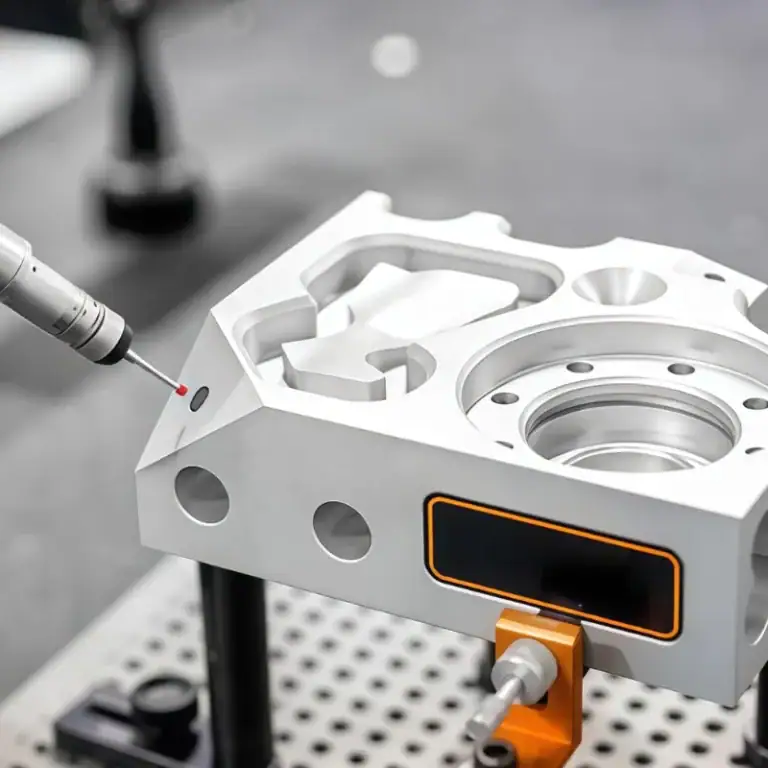
A coordinate measuring machine can collect tactile data from defined features and sections. Optical systems can provide dense surface information, particularly useful for visualizing deviations over an airfoil. Select coverage and uncertainty for the requirement rather than choosing equipment solely because it produces more points.
Alignment is part of the evaluation. An unconstrained surface best fit can conceal a relationship error that matters when the blade is installed through its root. Use the drawing’s reference scheme and document any permitted fitting method.
Separate Surface Texture From Material Condition
Profile error, waviness, and roughness describe different aspects of the finished surface. A blade can have a smooth local finish while its overall airfoil shape is wrong. A roughness reading also does not identify every possible crack or subsurface defect.
Where required, use specified nondestructive testing or internal inspection. Computed tomography (CT) or radiographic methods can support certain internal evaluations, but suitability depends on material, geometry, resolution, and the defect or dimension being assessed.
The inspection package should therefore connect each requirement with a suitable method. Avoid treating a surface scan, dimensional report, or polished appearance as evidence of every other quality characteristic.
Confirm The Delivered Condition
Record the drawing revision, material identity, evaluated features, alignment, measurement method, and results. Identify whether the report describes the machined, heat-treated, coated, or fully finished condition.
On-machine probing can support setup and process control, while acceptance inspection must satisfy the agreed measurement plan. If an intermediate check is used as acceptance evidence, its scope and suitability need to be established explicitly.
For repeated orders, agree on how tool changes, fixture changes, and process revisions will be evaluated. A passing first article demonstrates the inspected article’s condition. Production consistency requires appropriate ongoing controls and records.
What Should A Blade Machining RFQ Include?
A useful blade machining request for quotation (RFQ) includes the CAD model, controlled drawing, material and blank condition, critical geometry, finishing requirements, and acceptance documentation. Identify the intended component and production status so suppliers can evaluate the actual manufacturing scope rather than quote an unspecified blade shape.
For precision machining of turbine engine parts, the difference between a development model and service hardware affects the required material, processes, and approval evidence. Make that status clear at the start.
| RFQ Item | Information To Supply |
| Product definition | CAD model, drawing revision, component type, and intended use |
| Starting material | Exact grade, condition, stock form, and who supplies the blank |
| Critical geometry | Airfoil profiles, datums, root interfaces, edges, and thin sections |
| Special features | Cooling holes, internal passages, inaccessible areas, and existing coatings |
| Finishing scope | Grinding, polishing, edge conditioning, treatment, and coating requirements |
| Acceptance | Required reports, measurement conditions, special testing, and customer approvals |
| Order scope | Quantity, repeat-order expectations, delivery needs, and supplied-part responsibilities |
Compare proposals against the same requirements. Ask which operations are included, which need specialist processing, and what evidence accompanies the delivered part. Resolve proposed tolerance or process changes before production, with the approved product definition updated where necessary.
FAQs
Can CNC Machining Replace Casting For Turbine Blades?
Only when the design and material requirements allow it. Machining ordinary bar stock cannot reproduce the single-crystal or directionally solidified structure required by some turbine blades. CNC machining often complements casting by finishing roots, tips, and selected surfaces.
What Tolerances Can Blade Machining Achieve?
Achievable tolerances depend on material, geometry, workholding, and process control. Airfoil profile, thickness, root dimensions, and edge geometry require separate specifications. Capability should be confirmed against the drawing and inspection plan, rather than machine positioning accuracy alone.
What Determines The Cost Of Blade Machining?
Major cost factors include material, blank condition, stock removal, geometry, tooling, order quantity, and inspection. Specified grinding, cooling holes, and coatings add further operations. Compare quotations using the same drawing revision, material requirements, finishing scope, and acceptance criteria.
Conclusion
Blade machining requires a process that connects the starting blank to the finished airfoil and attachment geometry. Material selection, staged stock removal, tool orientation, and suitable finishing methods all influence whether the part can meet its requirements.
For engineers and buyers, the strongest starting point is a complete product definition and an agreed inspection plan. These make manufacturing proposals easier to compare and help prevent appearance or axis count from being mistaken for proof of quality.
TiRapid provides CNC machining services for custom parts. Send your drawing and CAD model with the material, blank condition, critical blade features, quantity, finishing requirements, and inspection expectations for a project-specific assessment. Include any required process qualifications so the manufacturing and verification scope can be discussed before ordering.