How are turbine blades made? Turbine blades are precision-engineered components manufactured through carefully controlled material preparation, CNC machining, grinding, polishing, and quality inspection. Depending on the blade design, 5-axis CNC milling refines complex airfoil profiles, while precision grinding and finishing control blade-root geometry, surface roughness, and critical dimensions to ensure accurate assembly and reliable performance.
This guide explains how turbine blades are made, focusing on CNC machining processes, engineering materials, 5-axis milling, airfoil profiling, blade-root machining, cooling-hole production, surface finishing, and inspection.
What Are Turbine Blades and How Are They Used?
Turbine blades are aerodynamic components that extract energy from moving steam or hot gas and transfer it to a rotating shaft. They are used in jet engines, industrial gas turbines, and steam turbines, where their geometry and material properties directly affect efficiency and reliability. Precision machining controls critical blade features, attachment interfaces, and surface conditions needed for accurate assembly and stable operation.
Turbine Blade Structure: Airfoil, Root, Platform, and Edges
A turbine blade typically consists of an airfoil, root, platform, and leading and trailing edges. The airfoil interacts with the working fluid, while the root secures the blade to the rotor. The platform helps define the flow passage and provides an interface between the airfoil and attachment region.
The airfoil has a curved three-dimensional profile designed to control fluid direction and energy transfer. Its thickness, curvature, twist, and edge geometry are carefully specified. Deviations in these features can affect aerodynamic performance, while root errors can prevent correct installation.
CNC machining requirements differ across these regions. Multi-axis milling or controlled finishing may be used for airfoil surfaces, while precision grinding is frequently applied to fir-tree roots and other demanding attachment geometries.
| Blade Feature | Main Function | Manufacturing Requirement |
| Airfoil | Directs fluid flow and extracts energy | Accurate profile and controlled surface finish |
| Leading edge | Guides incoming flow | Controlled radius and edge geometry |
| Trailing edge | Controls flow exit | Accurate thickness and smooth transition |
| Root | Secures the blade to the rotor | Precise dimensions and contact surfaces |
| Platform | Defines part of the flow passage | Accurate location and geometry |
| Cooling holes | Provide cooling airflow on applicable blades | Accurate position, size, and flow characteristics |
Jet Engine, Gas Turbine, and Steam Turbine Blades
Jet engine turbine blades extract energy from high-temperature combustion gases to drive the compressor and other rotating systems. A high pressure turbine blade works in one of the engine’s most demanding thermal and mechanical environments.
Industrial gas turbines use similar energy-conversion principles but are optimized for stationary power generation or mechanical drive applications. Blade size, operating cycles, maintenance requirements, and material specifications may differ from those used in aircraft engines.
Steam turbine blades extract energy from expanding steam and can operate under very different conditions. Long low-pressure steam turbine blades, for example, require careful attention to centrifugal loading, vibration, moisture-related erosion, and dimensional consistency.
Metal Turbine Blades vs. Composite Wind Turbine Blades
Metal turbine blades and composite wind turbine blades differ in their functions, materials, dimensions, and production methods. Metal blades used in gas and steam turbines are generally compact components designed for demanding thermal and mechanical conditions.
Wind turbine blades are much larger aerodynamic structures, typically manufactured from fiberglass or carbon-fiber composites combined with resin and internal reinforcement. Their main production process involves composite layup, resin infusion, curing, bonding, and structural inspection.
CNC machining plays different roles in these applications. It may directly machine or finish metal turbine blade features, while wind turbine manufacturing uses CNC equipment mainly for molds, fixtures, tooling, trimming, and accurately positioned interfaces.
| Factor | Metal Turbine Blades | Wind Turbine Blades |
| Typical materials | Nickel alloys, steels, selected titanium alloys | Fiberglass and carbon-fiber composites |
| Main application | Gas and steam energy conversion | Wind energy capture |
| Typical manufacturing approach | Near-net-shape preparation and precision machining | Composite molding and assembly |
| CNC applications | Airfoils, roots, platforms, local features | Molds, tooling, fixtures, trimming |
| Main quality concerns | Dimensional accuracy, surface integrity, material condition | Structural bonding, fiber quality, fatigue resistance |
What Materials Are Used for Turbine Blade Machining?
Turbine blade machining uses nickel-based superalloys, stainless steels, heat-resistant alloys, and selected titanium alloys, depending on the component and operating environment. Nickel-based superalloys are important for hot-section turbine blades, while titanium is more common in compressor components and certain lower-temperature applications. Material selection determines cutting parameters, tool wear, surface integrity, and machining cost.
Nickel-Based Superalloys for High-Pressure Turbine Blades
Nickel-based superalloys are widely used for high-temperature turbine components because they retain useful strength and resist creep, oxidation, and mechanical degradation at elevated temperatures. Advanced high-pressure turbine blades may use directionally solidified or single-crystal alloy structures.
These materials are challenging to machine because they maintain strength at high cutting temperatures and can accelerate tool wear. Heat is concentrated near the cutting zone, making stable machining parameters and effective thermal management especially important.
Precision finishing must also protect the material’s surface integrity. Excessive machining heat, aggressive grinding, or unsuitable tool engagement can create undesirable surface conditions that affect fatigue performance and component durability.
Titanium Alloys for Compressor and Lower-Temperature Blades
Titanium alloys provide high strength relative to weight and good corrosion resistance. They are particularly important in aircraft engine fans and compressors, where reducing rotating mass provides major engineering benefits.
Titanium is not the normal choice for the hottest high-pressure turbine stages because its elevated-temperature capability is insufficient for those environments. Selected titanium alloys may be used in lower-temperature turbomachinery applications where their properties meet the requirements.
During CNC machining, titanium’s relatively low thermal conductivity and strong chemical interaction with cutting tools can cause localized heat and accelerated tool wear. Appropriate cutting speeds, sharp tools, stable engagement, and suitable coolant delivery help manage these problems.
Stainless Steel and Heat-Resistant Alloys
Stainless steels and other heat-resistant alloys are used in selected steam turbine blades, industrial turbine components, and related mechanical systems. Their suitability depends on operating temperature, corrosion exposure, fatigue loading, and required mechanical properties.
Martensitic stainless steels can provide useful strength and corrosion resistance for certain steam turbine applications. Other alloy families may be selected when greater temperature resistance or specialized mechanical properties are required.
These materials can introduce machining challenges such as work hardening, tool wear, and residual stress. A suitable process plan must balance cutting efficiency with the required dimensional accuracy and final surface condition.
How Material Properties Affect CNC Machinability
Material properties affect CNC machinability by changing cutting forces, heat generation, chip formation, tool wear, and dimensional stability. A parameter set suitable for stainless steel should not automatically be applied to titanium or nickel-based superalloys.
Nickel-based alloys can retain significant strength during cutting, while titanium often concentrates heat near the cutting edge. Stainless steels may work-harden when tools rub instead of cutting effectively.
Engineers should match cutting strategies to the specific alloy grade, heat-treatment condition, tool geometry, and component design.
| Material Group | Typical Application | Main Machining Challenge | Process Priority |
| Nickel-based superalloys | Hot-section turbine components | Tool wear and cutting heat | Controlled engagement and surface integrity |
| Titanium alloys | Compressor and selected lower-temperature blades | Heat concentration and tool wear | Tool selection and cooling |
| Martensitic stainless steels | Steam turbine components | Tool wear and material response | Stable cutting and finishing |
| Other heat-resistant alloys | Specialized industrial turbine components | High cutting resistance | Suitable tooling and parameter control |
How Are Turbine Blades CNC Machined Step by Step?
Turbine blades are CNC machined through a sequence that typically includes CAD/CAM preparation, workpiece inspection, rough machining where necessary, 5-axis airfoil machining, blade-root and platform finishing, specialized hole production, surface finishing, and final inspection. Not every blade requires all these operations, because the amount of machining depends on the starting blank and its manufacturing route.

| Manufacturing Stage | Main Operation | Engineering Purpose |
| 1. CAD/CAM | Model review and toolpath generation | Define geometry and machine movements |
| 2. Workpiece preparation | Material verification and datum setup | Establish a reliable starting condition |
| 3. Rough machining | Remove designated stock allowance | Prepare the component for finishing |
| 4. Airfoil machining | Multi-axis profiling | Control aerodynamic surfaces |
| 5. Root and platform machining | Precision milling or grinding | Establish accurate assembly interfaces |
| 6. Hole production | CNC drilling, laser processing, or EDM | Produce specified cooling or functional holes |
| 7. Finishing | Grinding, polishing, and deburring | Improve surface and edge quality |
| 8. Inspection | Dimensional and surface verification | Confirm drawing compliance |
CAD Modeling and CAM Toolpath Programming
CAD modeling establishes the turbine blade’s three-dimensional geometry, including airfoil curvature, twist, leading and trailing edges, root dimensions, and platform features. The engineering model provides the reference for process planning and inspection.
CAM software converts the approved geometry into machining toolpaths. For complex airfoils, programming must account for tool orientation, collision avoidance, cutting engagement, surface finish, and suitable access to curved features.
Simulation is particularly important for 5-axis machining because rotary-axis movements can create collision risks that are not obvious in a two-dimensional toolpath view. Engineers should verify the complete setup, including fixtures and the available machine travel.
Workpiece Preparation and CNC Rough Machining
Workpiece preparation includes checking material identity, stock dimensions, component condition, and available machining allowance. The machinist must also identify the reference surfaces used to locate the blade accurately.
Rough machining removes excess material where the starting blank contains additional stock. On components machined from solid material, this can involve substantial material removal. Near-net-shape blades may require only limited local machining before finishing.
The objective is to remove material efficiently without damaging thin airfoil sections or introducing excessive stress. Controlled stock distribution and a stable sequence help prevent distortion during later precision operations.
5-Axis CNC Milling of Complex Airfoil Profiles
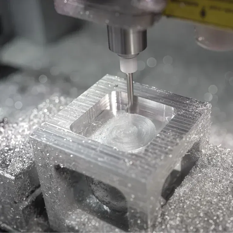
5-axis CNC milling is used to machine accessible complex airfoil surfaces by controlling tool movement along three linear axes and two rotary axes. This allows the cutter to maintain a suitable orientation as it follows curved and twisted blade geometry.
The process can machine suitable freeform surfaces with fewer setups than conventional three-axis milling. Ball-nose, barrel-shaped, or other specialized cutters may be selected according to the geometry, material, and finishing strategy.
Airfoil machining quality depends on toolpath spacing, cutting force, surface contact, and machine kinematics. Excessive step-over can leave visible scallop marks, while unsuitable tool orientation may cause rubbing, vibration, or inconsistent surface quality.
Precision Machining of Blade Roots and Platforms
Blade roots and platforms are precision machined to ensure accurate positioning, contact, and load transfer during turbine assembly. These regions are especially important because they connect the blade to the rotor and influence mechanical stability.
Fir-tree and dovetail root geometries can require specialized form grinding, profile grinding, or controlled multi-axis machining. The final process depends on the component design, tolerance requirements, and material condition.
Root geometry must be evaluated as a functional interface rather than a simple external shape. Errors in contact surfaces, angles, radii, or dimensional relationships can affect assembly loads and cause poor fitment.
Cooling Hole Drilling and EDM for Fine Features
Cooling holes are produced using specialized processes such as laser drilling, electrical discharge machining, and selected precision drilling methods. These features are important for turbine blades that use cooling air to manage extreme thermal conditions.
EDM removes electrically conductive material through controlled electrical discharges. It is useful for certain fine holes and difficult-to-machine alloys where conventional cutting tools may be unsuitable.
Internal serpentine cooling passages are generally not created by simply drilling through a completed solid blade. Their manufacturing route depends on the original component design, while external cooling holes may be added or finished through controlled secondary processing.
What CNC Machines and Cutting Tools Are Used for Turbine Blades?
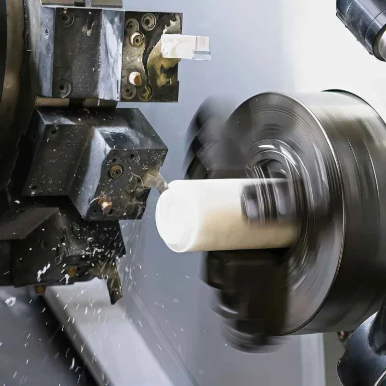
Turbine blade machining uses 5-axis CNC milling machines, precision grinding equipment, specialized cutting tools, and application-specific fixtures. The machine must provide suitable positioning accuracy, rigidity, tool access, and stable motion for complex blade geometry. Tool selection and workholding are equally important because turbine materials are difficult to cut and airfoil sections can deform under machining forces.
5-Axis CNC Milling Machines
5-axis machining centers provide additional tool orientation compared with three-axis machines, making them suitable for accessible curved blade profiles, twisted surfaces, and complex transitions.
Simultaneous 5-axis movement can help maintain favorable cutting angles as the cutter follows a blade’s freeform geometry. This can reduce the need for repeated setups and improve access to certain surfaces.
However, 5-axis capability does not guarantee the required accuracy. Machine calibration, thermal stability, tool condition, rotary-axis behavior, and fixture rigidity all influence the finished component.
Cutting Tools, Speeds, and Feed Strategies
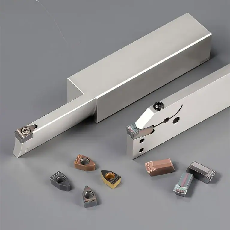
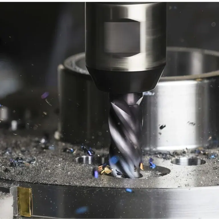
Cutting tools for turbine blade machining are selected according to the material, machining operation, surface geometry, and required quality. Carbide tools with suitable coatings are common for many difficult-alloy milling operations.
Cutting speed, feed per tooth, radial engagement, and depth of cut must be balanced to control heat and mechanical loading. Overly aggressive cutting can accelerate wear, while excessive rubbing can damage the machined surface.
Finishing operations generally require stable tool engagement and carefully controlled toolpath spacing. Cutting parameters should be validated for the specific material and machine rather than copied directly from unrelated production jobs.
Practical Tooling Considerations
- Select cutting-edge geometry suited to the alloy and operation.
- Minimize unnecessary tool overhang to improve rigidity.
- Maintain effective chip formation and evacuation.
- Control radial engagement when machining difficult alloys.
- Monitor tool wear before it affects critical surface geometry.
- Verify finishing parameters using suitable inspection methods.
Workholding, Fixtures, and Datum Control
Workholding supports the blade during machining while maintaining a consistent relationship between the component and machine coordinates. A suitable fixture must resist cutting forces without damaging or deforming thin airfoil sections.
Blade geometry often limits the available clamping surfaces. Fixtures may therefore support the root, platform, or specially designated reference regions while leaving the necessary machining areas accessible.
Datum control ensures that different operations use consistent reference features. This becomes especially important when a blade moves between milling, grinding, polishing, and inspection equipment.
| Setup Factor | Potential Problem | Practical Control |
| Clamping pressure | Airfoil distortion | Controlled clamping and support |
| Fixture stiffness | Vibration or movement | Rigid structure and secure location |
| Datum selection | Misaligned operations | Consistent reference features |
| Tool overhang | Deflection and chatter | Shorter tools where practical |
| Machine temperature | Dimensional variation | Thermal management |
| Tool access | Collision or unmachined regions | CAM simulation and fixture review |
How Are Turbine Blades Ground, Polished, and Finished?
Turbine blades are ground, polished, and finished using controlled abrasive processes that remove machining marks, refine airfoil surfaces, maintain edge geometry, and meet specified roughness requirements. CNC grinding and belt finishing provide repeatable material removal, while manual or robotic polishing may be used for selected features. Protective treatments are added when required by the component’s operating conditions.
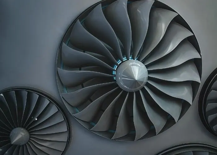
CNC Grinding and Belt Finishing
CNC grinding is used to achieve accurate geometry and suitable surface conditions on turbine components. Specialized grinding processes are particularly useful for blade roots and other features requiring controlled profiles.
CNC belt finishing uses abrasive belts to remove machining marks and improve curved airfoil surfaces. The process can be programmed to control tool movement, contact pressure, and material removal across complex contours.
Grinding and belt finishing must avoid excessive heat, edge rounding, or unwanted stock removal. The selected abrasive, contact conditions, coolant strategy, and inspection plan should match the specific component.
Manual Polishing vs. Robotic Finishing
Manual polishing provides flexibility for localized finishing, complex transitions, and operations requiring direct technician judgment. However, results can vary with operator experience, contact force, and working technique.
Robotic finishing improves process repeatability by controlling programmed movements and, where supported, contact force. It can be suitable for recurring blade families and production volumes that justify process development.
CNC finishing machines provide another controlled alternative, particularly when machine rigidity, predictable tool orientation, and reproducible abrasive contact are important.
| Finishing Method | Main Advantage | Main Limitation | Typical Use |
| Manual polishing | Flexible local adjustment | Operator-dependent consistency | Small areas and selected finishing tasks |
| CNC belt finishing | Repeatable programmed processing | Requires process development | Airfoil surface finishing |
| Robotic polishing | Flexible automation | Force and position control challenges | Repeated surface-finishing tasks |
| Precision grinding | Accurate geometric control | Thermal damage risk if poorly controlled | Root profiles and critical features |
Surface Roughness and Leading-Edge Control
Surface roughness and leading-edge geometry must be controlled because they influence aerodynamic surfaces and downstream processing. The required finish depends on blade design, operating conditions, and applicable manufacturing specifications.
Ra is a commonly used measure of average surface roughness, expressed in micrometers or microinches. A lower Ra generally indicates a smoother measured surface, but roughness alone does not describe the complete surface condition.
For reference, published industrial finishing examples include the following values. They are illustrative process targets, not universal requirements for all turbine blades.
| Blade Application | Illustrative Surface Roughness |
| Steam turbine blades | Ra 0.6–1.2 µm |
| Gas turbine blades and vanes | Ra 0.4–0.6 µm |
| Selected aircraft engine blades | Ra 0.4 µm or lower |
The final requirement must come from the drawing or applicable engineering specification. Leading-edge radii, trailing-edge thickness, waviness, and profile accuracy should also be inspected where functionally critical.
Protective Coatings and Post-Processing
Protective coatings and post-processing are applied to selected turbine blades to improve resistance to oxidation, corrosion, thermal exposure, or other service conditions. The treatment depends on material and application.
Certain high-temperature turbine components use thermal barrier coating systems to help reduce the temperature experienced by the metallic substrate. These coatings require controlled application and qualification by appropriately equipped specialists.
Post-processing may also include cleaning, deburring, surface treatment, or other specified operations. Coating thickness and process effects must be considered because treatments can change final dimensions and surface characteristics.
What Are the Main Challenges in CNC Turbine Blade Machining?
The main challenges in CNC turbine blade machining are rapid tool wear, excessive cutting heat, thin-airfoil deformation, machining vibration, and dimensional distortion caused by residual stress. These problems are especially important when machining heat-resistant alloys and slender freeform surfaces. Effective solutions combine suitable cutting strategies, stable workholding, controlled material removal, and inspection throughout production.
Tool Wear and Heat Control in Superalloys
Nickel-based superalloys create demanding cutting conditions because they retain mechanical strength at elevated temperatures. High cutting forces and concentrated heat can accelerate tool wear and reduce machining consistency.
Tool deterioration may change the effective cutting geometry, increase cutting resistance, and produce poor surface finishes. In precision finishing, even gradual wear can cause unacceptable dimensional variation.
The machining strategy should use suitable tool materials, stable cutting engagement, effective cooling where appropriate, and defined tool-condition monitoring. Cutting speed must be balanced against tool life and surface integrity.
Thin Airfoil Deflection and Machining Vibration
Thin airfoils can deflect under cutting forces because their stiffness changes along the blade length and across the profile. This can create dimensional errors even when the CNC machine follows the programmed path accurately.
Vibration can also occur when the workpiece, tool, or fixture lacks sufficient rigidity. Chatter marks may appear on finished surfaces, and unstable contact can accelerate tool wear.
To reduce these effects, engineers may use improved support, shorter tools, lighter finishing passes, balanced material removal, and toolpaths that reduce sudden changes in cutting load.
Residual Stress and Dimensional Distortion
Residual stress is internal stress that remains in a component before external forces are applied. Machining can change the stress distribution by removing material, potentially causing movement or distortion.
This is particularly important for thin components, asymmetric geometries, and parts requiring substantial stock removal. A blade that appears accurate while clamped may change shape after the fixture is released.
Controlled machining sequences, suitable intermediate inspection, and material-specific stress-management methods can reduce this risk. The appropriate approach depends on alloy condition, previous processing, and allowed heat treatment.
| Machining Challenge | Common Cause | Practical Response |
| Rapid tool wear | High-temperature alloy strength | Suitable cutting tools and controlled parameters |
| Surface damage | Excessive heat or rubbing | Stable chip formation and cooling |
| Airfoil deflection | Thin geometry and cutting forces | Improved support and lighter cuts |
| Chatter marks | Weak rigidity or unstable engagement | Fixture and toolpath optimization |
| Distortion after unclamping | Residual stress or clamping pressure | Balanced machining and inspection |
| Inconsistent finish | Tool wear or abrasive variation | Controlled tool life and finishing conditions |
How Are CNC-Machined Turbine Blades Inspected?
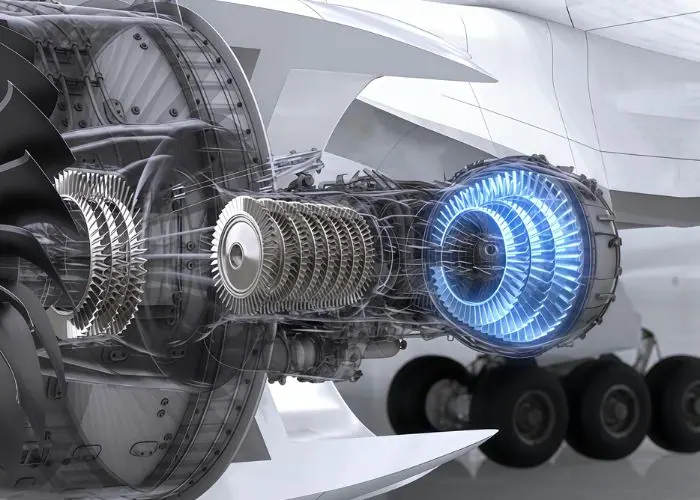
CNC-machined turbine blades are inspected using dimensional measurement, coordinate measuring machines, optical scanning, surface roughness measurement, and specialized testing methods. Inspection verifies airfoil geometry, root dimensions, edge profiles, cooling features, and specified surface requirements. Additional non-destructive testing and material traceability may be necessary for safety-critical components.
Airfoil Geometry and Dimensional Tolerances
Airfoil inspection verifies that the manufactured blade meets specified geometry and tolerance requirements. Critical features can include profile curvature, twist, thickness distribution, leading-edge radius, and root-to-airfoil alignment.
The engineering drawing determines which characteristics require measurement and what deviations are acceptable. A blade may satisfy one-dimensional measurements while still having unacceptable surface profile errors.
Dimensional control must therefore consider the complete geometry. Selected features may need individual measurements, while complex freeform surfaces benefit from profile comparison against the approved CAD model.
Coordinate Measuring Machines and Optical Scanning
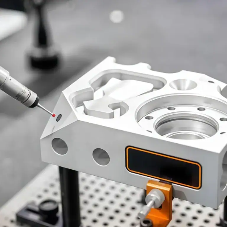
Coordinate measuring machines use calibrated probes to measure part geometry and compare results with specified dimensions. They are suitable for accurately evaluating blade roots, platforms, datum features, and selected airfoil sections.
Optical scanning captures large numbers of surface points to evaluate complex three-dimensional blade shapes. It can help identify local surface deviations that are difficult to detect through individual contact measurements.
Contact and optical methods are complementary. CMM inspection can provide precise feature measurements, while optical systems are valuable for full-surface analysis. Calibration, measurement uncertainty, datum alignment, and inspection planning remain essential for reliable results.
Surface Finish and Cooling Hole Inspection
Surface finish inspection verifies roughness, waviness, and visible defects according to the component specification. A surface roughness tester can measure Ra and other required parameters, but the measurement location and direction must be defined.
Cooling hole inspection evaluates feature position, opening geometry, and other specified characteristics. Optical systems and specialized measurement methods may be needed for small or angled holes.
For certain cooled turbine components, airflow testing can provide additional functional information. Dimensional inspection confirms geometry, while flow testing evaluates whether the completed cooling system meets its specified performance requirements.
Non-Destructive Testing and Quality Traceability
Non-destructive testing is used to evaluate specified material or component defects without destroying the finished part. Depending on the material and inspection requirement, methods may include fluorescent penetrant inspection, radiography, or other qualified techniques.
NDT is different from dimensional inspection. A blade may meet its geometric tolerances but contain defects that require a separate evaluation method. The testing method and acceptance limits should be defined by the applicable specification.
Quality traceability connects the finished component to its material documentation, manufacturing operations, inspection records, and relevant processing history. This is particularly important for aerospace and other critical turbine applications.
| Inspection Method | Main Purpose | Example Feature |
| CMM | Verify precise dimensions and geometry | Root and platform |
| Optical scanning | Compare complex surfaces with CAD | Airfoil profile |
| Surface roughness testing | Measure surface texture | Airfoil finish |
| Optical hole inspection | Check hole geometry and position | Cooling holes |
| Airflow testing | Verify specified flow performance | Cooling system |
| Non-destructive testing | Detect relevant material defects | Critical blade regions |
| Documentation review | Confirm material and process history | Traceability |
What Affects Turbine Blade CNC Machining Cost and Quality?
Turbine blade CNC machining cost and quality depend on material selection, component complexity, machine time, cutting-tool consumption, fixture design, finishing requirements, production volume, and inspection scope. Difficult-to-machine alloys and tight geometric requirements can increase manufacturing time. Process planning, stable machining strategies, and appropriate quality controls help reduce production risks and unnecessary cost.
Material Cost, Tooling, and Machining Time
Material cost depends on alloy grade, product form, certification requirements, and the amount of stock needed. Nickel-based superalloys and other specialized turbine materials may involve substantial material expenses.
Machining time is influenced by stock removal, blade geometry, tool access, number of setups, and required finishing operations. Multi-axis cutting can reduce repositioning, but complex programming and slower machining conditions may increase preparation or cycle time.
Tool wear is another important cost factor. A difficult alloy may require more frequent tool changes, additional finishing, or closer process monitoring than a conventional engineering material.
Prototyping vs. Batch Production
Prototype turbine blade machining emphasizes design verification, manufacturability, and the ability to adjust the process as engineering requirements change. Setup and programming costs may represent a large share of the initial manufacturing effort.
Batch production places greater emphasis on repeatability, tool-life management, fixture consistency, and inspection efficiency. Once the process is stable, programming and setup costs can be distributed across multiple components.
However, increasing quantity does not automatically reduce every cost. Specialized inspection, controlled processes, material traceability, and tool wear may continue to contribute significantly to each component.
| Cost Factor | Prototype Production | Batch Production |
| CAM programming | High initial contribution | Spread across repeated parts |
| Fixture development | May require trial setups | Can use dedicated fixtures |
| Tooling | Flexible selection | Optimized tool-life planning |
| Machining cycle | Focus on validation | Focus on stable repeatability |
| Inspection | Detailed first-part verification | Defined production inspection plan |
| Engineering changes | Easier to accommodate | May require process revalidation |
Choosing a Supplier for Precision Turbine Components
A suitable machining supplier should understand complex blade geometry, difficult materials, dimensional control, and the relationship between manufacturing operations and part performance. Equipment capability alone does not establish manufacturing suitability.
Engineering review should identify whether the component requires 5-axis machining, precision grinding, specialized hole processing, coating, NDT, or additional qualification. These requirements may involve different equipment and approved specialist processes.
Supplier evaluation should also consider inspection capability, process documentation, material traceability, and experience with comparable components. For safety-critical or regulated applications, the required certifications and production approvals must be verified before manufacturing begins.
FAQs
How Are Jet Turbine Blades Made?
Jet turbine blades are manufactured through a controlled process involving high-temperature alloy preparation, precision shaping, CNC machining, specialized finishing, and inspection. Many hot-section blades begin as near-net-shape components rather than being milled entirely from solid stock. CNC machining and precision grinding are used for critical features such as blade roots, platforms, and selected airfoil surfaces. Cooling holes may be produced by laser processing or EDM. Final operations can include polishing, protective coating, dimensional inspection, and material verification.
How Are Single Crystal Turbine Blades Made?
Single-crystal turbine blades are formed using controlled directional solidification of specialized nickel-based superalloys. A crystal selector or seed helps establish a continuous crystal orientation without conventional grain boundaries throughout the required blade region. This structure improves resistance to high-temperature creep. After the blade blank is produced, CNC machining, grinding, hole processing, and finishing create specified functional features. Quality control verifies crystal orientation, material integrity, geometry, and surface condition. CNC machining alone cannot create the single-crystal structure.
How Are Wind Turbine Blades Made?
Wind turbine blades are primarily manufactured from fiberglass or carbon-fiber composites rather than being cut from solid metal. A typical process involves preparing large molds, placing reinforcement layers, adding core materials, infusing resin, curing the composite structure, and joining the blade shells. The blade is then trimmed, finished, and inspected. CNC machining supports the production of molds, tooling, fixtures, and certain interfaces. Unlike jet engine turbine blades, wind turbine blades are large composite structures designed to capture wind energy.
What Is Single Crystal Blade Technology?
Single-crystal blade technology produces turbine components with a controlled crystallographic orientation and no conventional high-angle grain boundaries in the intended single-crystal region. This is important because grain boundaries can reduce resistance to creep under extreme thermal and mechanical loading. The technology is commonly associated with advanced nickel-based superalloys used in high-pressure turbine stages. Single-crystal formation requires specialized solidification control, followed by precision machining and finishing. The manufacturing process must also verify crystal quality, cooling features, and dimensional accuracy.
Conclusion
Turbine blade manufacturing requires precise control of material properties, complex geometry, machining forces, surface integrity, and inspection. CNC milling, grinding, polishing, and specialized finishing play important roles in producing accurate airfoil surfaces, blade roots, platforms, and functional features. Successful results depend on matching the machining process to the blade design, alloy characteristics, and service requirements. For engineers, understanding these manufacturing relationships helps reduce machining risks and improve the consistency of precision turbine components.
At TiRapid, we provide precision CNC machining and manufacturing services for custom metal components. Our team supports CNC milling, turning, DFM analysis, surface finishing, and dimensional inspection to help customers develop accurate, reliable, and manufacturable precision parts for demanding industrial applications.