A semiconductor shower head distributes process gases across a wafer through a carefully designed network of passages and outlet holes. Its geometry, material, and surface condition influence how consistently a chamber can perform deposition or etching. Manufacturing the part therefore involves more than producing a perforated plate.
For engineers and buyers, the practical questions are connected. Which surfaces contact the process gas? How are internal channels formed? What can CNC machining achieve, and which requirements need additional processes? This guide explains the component, the manufacturing decisions behind it, and the information needed to evaluate a supplier or prepare a machining inquiry.
What Is A Semiconductor Shower Head And How Does It Work?
A semiconductor shower head is a gas distribution component used in deposition and etching equipment. It spreads incoming gas through internal spaces and outlet passages, while its exact construction depends on the chamber and process.
The Faceplate And The Complete Shower Head Assembly
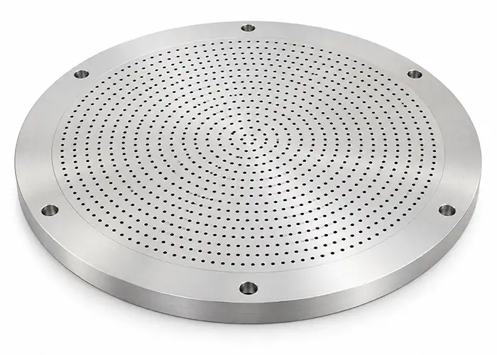
The faceplate is the perforated surface facing the wafer. A complete assembly may also contain a backing plate, gas inlet connections, internal distribution plates, seals, and temperature control features. Some designs integrate several functions into a bonded structure. Others use separately assembled components.
This distinction matters when reading drawings or comparing quotations. A supplier offering a machined faceplate may not be supplying the backing structure, joints, seals, or assembly testing. The drawing package should identify the ordered component and its relationship to the complete assembly.
The term gas distribution plate is also used, although equipment manufacturers may apply it to different parts of the gas delivery arrangement. Part numbers and assembly drawings are more reliable identifiers than terminology alone.
The Gas Path From The Inlet To The Wafer
Gas enters through a supply connection and travels into a distribution space, often called a plenum. Depending on the design, it passes through additional plates or channels before leaving the faceplate holes toward the process region.
Upstream equipment sets the supplied gas flow. The shower head influences how that flow is distributed spatially. Pressure differences and resistance through the internal passages determine how much gas reaches different outlet locations.
The surrounding chamber also matters. Exhaust arrangement, operating pressure, and the distance between the faceplate and wafer interact with the gas delivery design. A hole pattern cannot establish process uniformity independently of these conditions.
Applications In Deposition And Plasma Etching
In chemical vapor deposition, or CVD, the shower head delivers precursor gases toward the substrate. Plasma-enhanced CVD adds plasma activation, while atomic layer deposition, or ALD, uses controlled reactant exposure and purge sequences. Shower head arrangements differ among these processes and among equipment designs.
In plasma etching, the component distributes gases used to generate reactive species. In some capacitively coupled plasma systems, the shower head also serves as an electrode. That additional role introduces electrical requirements alongside gas delivery and thermal requirements.
These applications explain why apparently similar plates may require different materials, surface treatments, or internal structures. Matching the external dimensions is not sufficient to establish interchangeability.
Which Design Features Affect Shower Head Performance?
Gas distribution depends on the combined design of the outlet holes, internal gas spaces, and chamber interfaces. The objective is to achieve the required distribution under defined operating conditions, rather than maximize hole count or minimize hole diameter.
Hole Geometry, Pattern, And Gas Flow Resistance
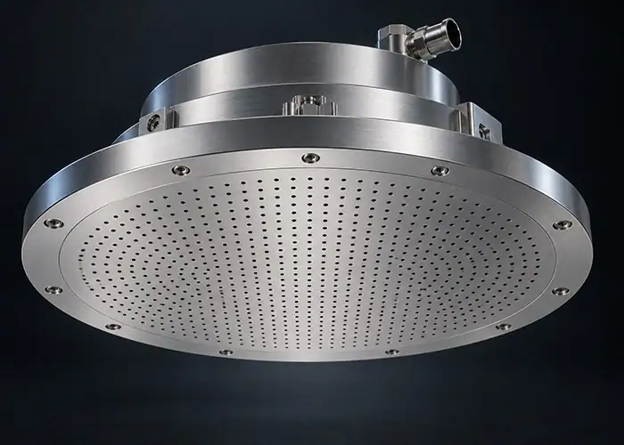
A hole’s diameter, length, and entrance or exit geometry affect its flow resistance. The relationship also depends on gas properties and operating pressure. Manufacturing variation can therefore change the flow delivered through a passage even when the hole remains visibly open.
Hole patterns may deliberately vary across a faceplate to address differences between central and outer regions. Consistency means reproducing each specified feature accurately, not assuming every hole must have the same diameter or spacing.
An engineering drawing should define functional details such as counterbores, stepped passages, and edge breaks. An unspecified chamfer added during deburring can change the intended entrance geometry. Changes to hole shape should be reviewed as design changes rather than treated as routine cosmetic improvements.
Internal Plenums And Separate Gas Distribution Zones
The plenum gives incoming gas space to redistribute before reaching the outlets. Its depth, inlet arrangement, and any intermediate distribution features influence the pressure available at different parts of the faceplate.
Some assemblies provide independently supplied regions to adjust gas delivery across the substrate. Others keep different reactants in separate passages until their intended point of introduction. These are distinct functions, and a design may incorporate either or both.
The manufacturer must preserve the separation defined by the drawings. Unintended leakage into an adjacent circuit can defeat the specified separation even when the individual channels meet their dimensional requirements. Internal joints and sealing boundaries therefore deserve the same attention as visible outlet holes.
Faceplate Geometry, Thermal Behavior, And Chamber Interfaces
Faceplate shape and mounting position establish the intended relationship to the wafer. For a nominally flat design, flatness and mounting parallelism help control the processing gap. Other designs use an intentional surface contour that must be inspected against the specified profile.
Operating temperature can change dimensions and introduce distortion. Thermal expansion differences between a faceplate and its support can also load joints or affect contact. Where heating or cooling features are included, their interfaces belong in the manufacturing review.
Seal grooves, mounting features, and electrical contact areas require clear functional definitions. A coating that is suitable on an exposed surface may be unsuitable on a contact interface. Drawings should distinguish these areas before manufacturing begins.
Which Materials Are Used For Semiconductor Shower Heads?
Material selection depends on process chemistry, plasma exposure, temperature, purity, and electrical function. Metals, silicon, silicon carbide, quartz, and oxide ceramics provide different combinations of properties, so the exposed surface and supporting structure may use different materials.
Aluminum Alloys And Other Metals
Aluminum alloys are used in metal shower head structures because they combine machinability with useful thermal conductivity and relatively low weight. They allow manufacturers to produce cavities, channels, mounting features, and hole patterns through established machining processes.
The exact alloy and condition still require approval for the application. Alloying constituents, thermal stability, and compatibility with process gases can matter more than general mechanical strength. A familiar structural alloy is not automatically suitable for a surface exposed to plasma.
Other metals may be specified for particular bodies, connections, or gas delivery environments. Selection should follow the required chemical and thermal conditions. Where a protective treatment is required, the substrate and treatment must be evaluated together, including coverage inside passages and the condition of interfaces left untreated.
Silicon And CVD Silicon Carbide
Silicon is used for shower head electrodes in plasma etching equipment. Purity, electrical properties, and behavior in the process environment help determine the specified grade. It is a brittle material, so hole damage and handling damage require careful control.
CVD silicon carbide is produced by chemical vapor deposition and can provide high purity, stiffness, and resistance to demanding chemical environments. Its electrical properties depend on the grade, which matters when the component has an electrode function.
Bulk CVD silicon carbide, sintered silicon carbide, and a substrate carrying a silicon carbide coating are different material systems. They should not be substituted solely because each description contains “SiC.” The drawing and material specification should identify the required construction, grade, and exposed surface.
Quartz And Oxide Ceramics
High-purity fused quartz is used for gas distribution components in suitable semiconductor processes. Its low thermal expansion and purity can be useful, but compatibility must be checked against the actual process and cleaning chemistry.
Oxide ceramics, including appropriate alumina grades, are also used in semiconductor chamber components and gas distribution applications. Electrical insulation, plasma resistance, purity, and mechanical integrity can all influence selection. Ceramic grade and manufacturing route affect the resulting properties.
Dense ceramic parts and ceramic coatings on metal substrates should be specified separately. A coated metal structure retains the thermal and mechanical behavior of its underlying substrate, while coating adhesion and integrity introduce additional requirements. Neither quartz nor an oxide ceramic should be described as universally resistant to every plasma or cleaning process.
How Are Semiconductor Shower Heads Manufactured?
Manufacturing combines material preparation, precision machining, and the additional operations required by the design. CNC forms controlled geometries, while specialized finishing, joining, surface treatment, and cleaning establish other essential features of the delivered component.
CNC Turning And Milling For Metal Components
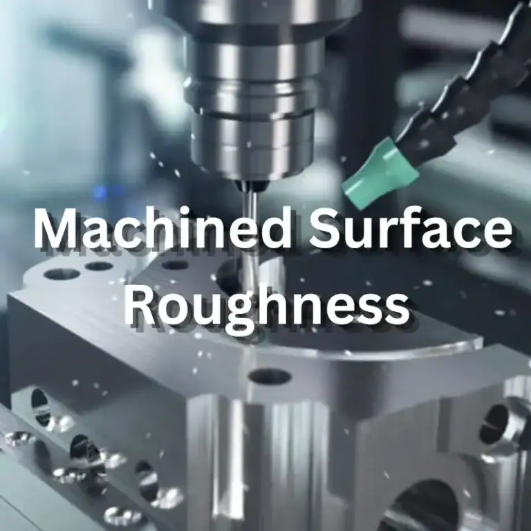
For metal components, CNC turning can establish rotational features such as outer diameters, shoulders, and end faces. Milling produces pockets, open channels, mounting details, and nonrotational features. The process plan should establish datums that remain meaningful through later operations and inspection.
Material removal and clamping can distort a relatively thin plate. Roughing and finishing sequences, support locations, and clamping loads therefore need to suit the geometry. A part that appears flat while restrained may move after release.
Where internal channels will be enclosed by another plate, machining must account for the subsequent joint. Channel walls, bonding lands, and alignment features need appropriate dimensions and surface conditions. CNC provides access to these details before assembly makes them difficult or impossible to reach.
Precision Drilling For Gas Distribution Holes
Drilling strategy depends on the material, hole diameter, depth, and access. Spindle accuracy, tool runout, tool condition, feed control, and debris removal all influence the result. A general machining center may suit some features, while demanding hole arrays may require dedicated equipment.
For metal drilling, chip evacuation becomes more difficult as passages become narrower or deeper. Process development must consider how to avoid chip packing, tool deflection, and damage at breakthrough. Tool monitoring and inspection during production help identify changes before they affect an entire array.
Deburring is a separate manufacturing concern. The chosen method must remove unwanted material while preserving the specified edge shape and passage dimensions. Abrasive flow finishing can be suitable for some geometries, but its material removal and subsequent cleaning requirements must be qualified for the part. Blowing air through a hole does not establish that it is burr-free.
Grinding And Specialized Machining For Brittle Materials
Silicon, quartz, and ceramics require processes developed for brittle behavior. Excessive local forces can create chipped edges or cracks, including damage beneath a surface that appears acceptable during a simple visual check.
Depending on the material and feature, production may combine sawing, CNC grinding, specialized drilling, lapping, and polishing. Diamond tooling or ultrasonic assistance may be appropriate for selected operations. The process should be chosen from demonstrated results for the material and geometry, rather than assumed necessary for every brittle part.
CNC remains relevant because it controls tool motion and feature location, including on grinding equipment. However, machining capability for aluminum does not establish equivalent capability for silicon electrodes. Suitable tooling, damage control, cleaning, and inspection are integral to the brittle-material process.
Bonding And Joining For Enclosed Channels
Some assemblies are manufactured by machining accessible passages into separate layers and then joining those layers. This approach can create enclosed paths that a cutting tool cannot directly produce inside a solid plate.
Available methods include diffusion bonding, brazing, and other joining processes selected for the material system and assembly design. In direct solid-state diffusion bonding, heat and pressure promote bonding across prepared interfaces. Brazing uses a filler metal, whose compatibility with the component and process environment must be assessed.
Joint preparation includes surface condition, alignment, and cleanliness. The joining cycle can also affect dimensions, so the manufacturing plan must identify any subsequent finishing and inspection. Bonding lands should be checked before joining, while features affected by the joining cycle should be evaluated in their final condition. Mechanically assembled designs have different requirements for seals and contact surfaces. The appropriate construction follows the equipment design rather than a universal preference for bonded assemblies.
Surface Treatment, Final Cleaning, And Packaging
Specified treatments may protect exposed surfaces or provide required electrical characteristics. For metal components, these can include suitable anodizing or ceramic coating systems. Treatment selection must account for the substrate, process chemistry, and intended surface function.
The sequence of treatment and hole finishing needs particular attention. Added layers can affect passage dimensions, while post-treatment machining can expose underlying material. Masking requirements and final dimensional acceptance should therefore be defined together.
Cleaning removes machining fluids, particles, and residues using a process compatible with the finished component. Rinsing and drying must reach the relevant passages without damaging surfaces or leaving unacceptable residues. Packaging then preserves the achieved condition during storage and transport. Clean handling is part of this sequence, not a substitute for a qualified cleaning process.
How Is Shower Head Quality Verified?
Verification should distinguish geometric conformity, surface cleanliness, and assembly performance. Inspection methods and acceptance limits must match the supplied part, with additional functional testing defined where dimensional measurements cannot establish compliance.
Dimensional And Hole Quality Inspection
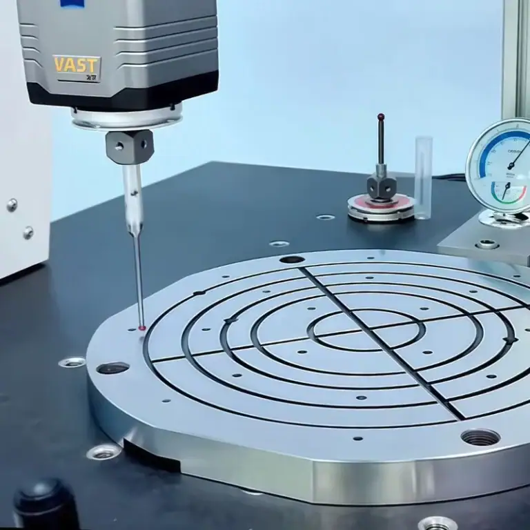
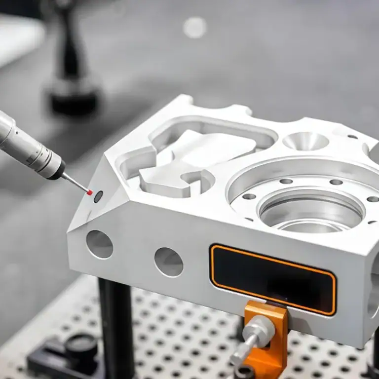
Inspection starts with the drawing datums and critical relationships. Outer dimensions alone provide little information about the accuracy of the gas delivery features. Hole position, passage geometry, face profile, and sealing interfaces need methods suited to their size and accessibility.
| Feature | Possible Verification Method | Main Limitation To Address |
| External dimensions and mounting features | Coordinate measurement or suitable gauges | Fixture alignment and datum interpretation |
| Hole openings and positions | Optical or vision measurement | An opening measurement does not establish the full internal profile |
| Flatness or specified face profile | Appropriate surface metrology | Support conditions and measurement coverage |
| Accessible surface texture | Contact or optical profilometry | Access and suitability for the material |
| Internal passages and edges | Qualified imaging or specialized inspection | Resolution and visibility of hidden defects |
The inspection plan should define coverage, instrument capability, and reporting requirements before production. Features that become inaccessible after joining may require inspection at an earlier stage.
Surface Condition And Cleanliness Verification
A visually clean surface can still carry fine particles, chemical residue, or trace contamination. Acceptance should therefore identify what must be controlled and how it will be evaluated.
Depending on the specification, checks may address particles, residual contamination, coating condition, or damage around hole edges. Surface roughness and cleanliness are different properties. A smooth surface is not automatically clean, and cleaning cannot correct a dimensional defect.
The inspection and handling sequence also needs attention. Contact gauges, test fixtures, or assembly operations may introduce contamination after cleaning. The agreed workflow should establish when verification occurs and whether additional cleaning is required before final packaging. Records should link the delivered part to its cleaning and inspection status.
Leak Testing And Gas Distribution Validation
For assemblies with separate circuits, testing may need to detect leakage between channels as well as leakage across external boundaries. A test that confirms an external seal does not automatically establish isolation between internal gas paths. Because outlet holes are intentional openings, suitable fixtures must isolate the circuit being tested and distinguish leakage from intended flow.
Leak testing and flow testing answer different questions. The former checks unintended gas passage, while the latter evaluates delivery through the intended paths. Test gas, pressure conditions, temperature, fixtures, and acceptance criteria must be defined so results can be interpreted consistently.
Component testing also differs from chamber process qualification. A measured gas distribution does not by itself prove a particular film or etch result. The equipment or process team must validate performance under the relevant operating recipe. Quotations should identify who supplies fixtures, performs testing, and approves the results.
What Should Buyers Specify Before Requesting A Quote?
A useful quotation package defines the component, its manufacturing requirements, and the evidence needed for acceptance. Clear scope allows suppliers to assess feasibility and quote the same deliverable, rather than make different assumptions about finishing or testing.
Drawings, Materials, And Critical Requirements
Provide the current engineering drawing and a matching CAD model. Identify the material grade, condition, and any restrictions on substitutions. The drawing should distinguish gas-contact surfaces, mating interfaces, and features requiring special protection or finishing.
The package should also include:
- Hole geometry, pattern definitions, and datum references.
- Critical dimensional and geometric tolerances.
- Surface texture, edge condition, and coating requirements.
- Cleaning, handling, and packaging specifications.
- Order quantity, prototype needs, and revision status.
Where operating conditions affect manufacturing choices, provide the relevant temperature, chemistry, and plasma exposure information. If these details are confidential, identify the controlling material or process specification instead. Highlight unresolved requirements so the supplier can address them during feasibility review rather than silently assume an answer.
Supply Scope, Documentation, And Acceptance Criteria
State whether the order covers a faceplate, a backing component, a bonded structure, or a complete assembly. Identify responsibility for purchased seals, joining, coating, cleaning, and functional tests. A supplier’s machining scope may cover only part of that sequence.
Request the records needed for acceptance, such as material traceability, dimensional reports, approved process records, or specified test results. Confirm how drawing revisions and process changes will be controlled, especially when moving from a prototype to repeat production.
Compare quotations against these requirements before comparing price. A lower quotation may exclude cleaning, fixtures, or inspection included elsewhere. Establishing a common delivery scope makes both the commercial comparison and technical approval more useful.
FAQs
Does Every Semiconductor Shower Head Also Act As An Electrode?
No. Some shower heads also serve as electrodes in capacitively coupled plasma systems. Others primarily distribute gas. The chamber design determines whether the component needs electrical conductivity, insulation, or specific contact interfaces.
Do More Holes Improve Shower Head Performance?
Not necessarily. Gas distribution depends on hole size, length, spacing, internal channels, and chamber conditions. Adding holes changes flow resistance and may disrupt the intended distribution. Hole patterns should be validated for the operating process.
What Is The Difference Between Leak Testing And Flow Testing?
Leak testing checks for unintended gas passage across seals or between separate circuits. Flow testing evaluates gas delivery through the intended passages. Passing a leak test does not establish that the shower head meets its gas distribution requirements.
Conclusion
A semiconductor shower head must reproduce the gas delivery geometry, material properties, and surface condition required by its chamber design. CNC machining creates many of the critical features, while joining, finishing, cleaning, and verification complete the manufacturing route where required. Defining these requirements together helps engineers and buyers evaluate feasibility and distinguish a dimensionally acceptable component from an assembly ready for its agreed qualification stage.
TiRapid provides custom CNC machining services for precision components. Send your shower head component drawings, material specifications, critical tolerances, and order quantity for a manufacturability review. Include surface treatment, cleanliness, and inspection requirements so the team can assess the machining scope and clarify the additional processes needed for your project.