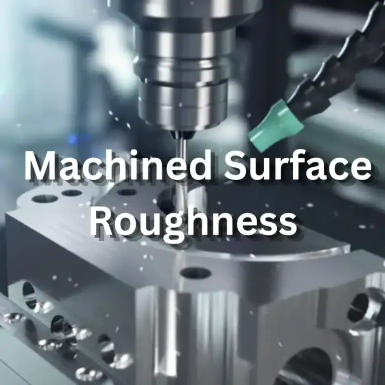
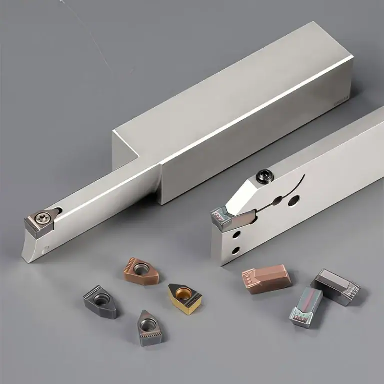
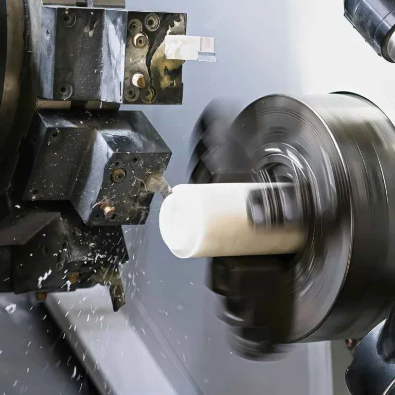
Machined surface roughness describes the microscopic peaks and valleys left on a part after cutting. These irregularities may be too small to see clearly, but they can influence friction, sealing, wear, lubrication, coating adhesion, fatigue behavior, dimensional fit, and appearance. A smoother surface is not automatically better,the correct finish depends on how the part will function.
This guide explains machined surface roughness, Ra and Rz values, surface roughness charts, drawing symbols, measurement methods, CNC process factors, milling and turning differences, and practical ways to improve finish. It also explains how to choose a suitable roughness requirement without adding unnecessary machining time and cost.
What Is Machined Surface Roughness?
Machined surface roughness is the fine-scale texture left by a cutting process. It is created by tool geometry, feed motion, material behavior, vibration, tool wear, and other machining conditions. Roughness is only one part of overall surface texture, but it is usually the parameter most frequently specified on CNC drawings.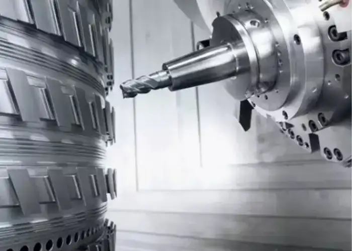
How CNC Machining Creates Surface Peaks And Valleys
A cutting tool does not leave a perfectly flat surface at microscopic scale. Each pass creates small ridges, valleys, feed marks, or scallops.
In turning, the tool nose radius and feed per revolution create a repeating profile along the surface. In milling, tooth engagement, step-over, tool runout, and cutter geometry produce their own characteristic marks.
Material behavior also changes the result. Aluminum may cut cleanly with a sharp tool, while stainless steel can generate built-up edge or tearing if cutting conditions are poor.
Surface Roughness Vs Surface Finish
Surface roughness is a measurable component of surface texture.
Surface finish is a broader term that may include roughness, waviness, lay, defects, and the visual appearance of a machined surface.
A part can therefore have an acceptable Ra value but still show chatter marks, scratches, or directional tool patterns that make it unsuitable for its application.
Roughness Vs Waviness Vs Lay
Roughness consists of relatively small, closely spaced surface irregularities.
Waviness refers to larger and more widely spaced variations, often caused by vibration, machine deflection, thermal movement, or fixture instability.
Lay describes the dominant direction of the surface pattern. Turning usually produces a circumferential lay, while face milling creates a different directional pattern.
These three characteristics should not be treated as the same thing.
Why Surface Roughness Matters For CNC Parts
Surface texture affects how two parts contact each other.
A sealing face may leak if the texture is too rough or oriented incorrectly. A sliding surface can wear rapidly if asperities are too high. A bearing seat may require a controlled finish for stable contact.
Roughness can also affect coating adhesion and appearance. For this reason, surface finish should be specified according to function rather than simply asking for the lowest possible Ra.
What Are The Main Surface Roughness Parameters?
Ra is the most widely recognized roughness parameter, but it does not describe every surface feature. Rz, Rq, Rt, and other parameters provide additional information about profile height and variation. NIST surface calibration work includes parameters such as Ra, Rq, Rz, and Rt, showing why surface texture cannot always be represented by one number alone.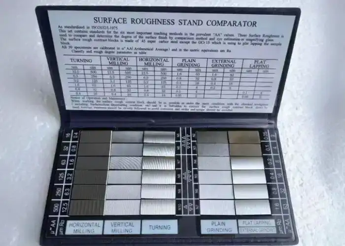
Ra: Average Surface Roughness
Ra is the arithmetic average of the absolute deviations of the roughness profile from its mean line over an evaluation length.
In practical CNC manufacturing, Ra is commonly used because it provides a simple, widely understood number for comparing surfaces.
A lower Ra generally indicates a smoother average surface, but it does not tell you how individual peaks or deep valleys are distributed.
Rz: Peak-To-Valley Surface Roughness
Rz evaluates vertical profile height using peak and valley information over sampling sections.
Because it is more sensitive to pronounced peaks and valleys than Ra, Rz can reveal surface characteristics that an average value may hide.
This can be useful for sealing, wear, and contact surfaces where an isolated deep valley or high peak matters more than the overall average.
Rq: Root Mean Square Roughness
Rq is the root mean square of profile deviations.
Because larger deviations are weighted more strongly than with a simple arithmetic average, Rq can be more sensitive to significant peaks and valleys.
It is less commonly specified on everyday CNC drawings than Ra but is useful in technical analysis and surface characterization.
Rt: Total Profile Height
Rt represents the vertical distance between the highest peak and lowest valley within the evaluated profile.
It is therefore sensitive to isolated surface defects.
A surface can have a reasonable Ra while still having a large Rt if one scratch, gouge, or high peak exists.
When To Use Ra Vs Rz
Ra works well for general manufacturing communication because it gives a stable average representation.
Rz becomes useful when peak-to-valley behavior affects function.
For example, two sealing surfaces may have similar Ra values but different Rz values because one contains deeper valleys.
Engineers should therefore specify the parameter that reflects the actual functional concern rather than assuming Ra alone describes every surface.
How To Read A Surface Roughness Chart And Ra Values
A surface roughness chart helps compare roughness values, units, historical N grades, and practical machining levels. The values should be used as guidance rather than universal process guarantees because achievable finish depends on machine condition, tool geometry, material, cutting parameters, and measurement method.
| Typical Ra | Microinches Approx. | General Interpretation |
| 6.3 µm | 250 µin | Rough machined surface |
| 3.2 µm | 125 µin | General CNC machined finish |
| 1.6 µm | 63 µin | Fine machined / precision finish |
| 0.8 µm | 32 µin | Fine functional surface |
| 0.4 µm | 16 µin | Very fine finish, often requiring controlled finishing |
| 0.2 µm | 8 µin | High-quality finish, frequently requiring specialized processes |
Micrometers Vs Microinches
Metric drawings usually express roughness in micrometers.
US drawings may use microinches.
The two units describe the same physical surface scale but use different numerical values. For example, approximately 1.6 µm corresponds to about 63 µin.
Always confirm the units before accepting or quoting a finish requirement.
Surface Roughness Grades From N1 To N12
Older or legacy drawings may use N grades to represent roughness levels.
Lower N numbers correspond to smoother surfaces, while higher numbers represent rougher finishes.
Modern drawings increasingly specify the actual roughness parameter and value because this provides clearer measurement information.
Ra 6.3 For Rough Machining
Ra 6.3 µm can be suitable where surface texture is not highly functional and the main objective is material removal.
It may be found on hidden structural faces, rough-machined stock, or noncritical areas.
The actual appearance can still vary considerably depending on milling, turning, material, and tool condition.
Ra 3.2 For General CNC Machining
Ra 3.2 µm is a widely encountered general-machining level. Some CNC suppliers use 3.2 µm Ra as their standard as-machined finish, although this is a supplier capability or commercial convention rather than a universal machining standard.
For many housings, brackets, plates, and general mechanical components, this level provides a practical balance between surface quality and production efficiency.
Surface Finish Ra 1.6 For Precision Machined Parts
A surface finish Ra 1.6 requirement usually calls for more controlled finishing than ordinary rough machining.
It may require a dedicated finishing toolpath, lower feed, good machine rigidity, stable workholding, and a sharp cutting edge.
Ra 1.6 is commonly considered when surfaces have functional contact, appearance, sliding, or more demanding assembly requirements.
Ra 0.8 And Below For Fine Functional Surfaces
Ra 0.8 µm and lower typically require tighter control of the entire machining system.
Tool runout, vibration, material behavior, coolant condition, and finishing allowance become more important.
At very low Ra values, turning or milling may no longer be the most economical route. Grinding, honing, lapping, or polishing may provide better process capability.
Why Ra And Rz Should Not Be Directly Converted
Ra and Rz describe different aspects of the profile.
Approximate conversion ratios sometimes appear in reference charts, but there is no universal fixed conversion that accurately applies to every surface.
Different manufacturing processes can produce the same Ra with very different peak-to-valley structures. For engineering work, use the specified parameter rather than relying on a rough conversion.
How To Read Surface Roughness Symbols On Engineering Drawings
A surface roughness symbol communicates more than a single Ra value. Depending on the drawing standard, it can indicate whether material removal is required or prohibited, which roughness parameter applies, the acceptable limit, process information, machining allowance, and surface lay. ISO 21920-1:2021 defines the current ISO rules for indicating profile surface texture with graphical symbols.
Basic Surface Roughness Symbol
The basic symbol identifies a surface texture requirement.
Additional information is then placed around the symbol according to the applicable drawing standard.
The reader should not interpret the graphical mark alone,the parameter designation and tolerance value are equally important.
Material Removal Required Or Prohibited Symbols
Different symbol forms can indicate whether material may be produced by any process, whether material removal is required, or whether removal is prohibited.
This matters for cast, forged, molded, ground, or otherwise processed surfaces.
Machining a surface marked to remain uncut can violate design intent even when its dimensions remain acceptable. ISO 21920-1 explicitly defines graphical symbol variants for these production conditions.
How Ra Values Are Shown On Drawings
A roughness callout should identify the parameter and its required value according to the specified standard.
Modern ISO practice under ISO 21920 uses parameter designations such as Ra or Rz with the tolerance limit, rather than relying only on an unlabeled number.
This reduces ambiguity and helps the manufacturer select the correct measurement method.
Surface Lay Direction Symbols
Lay symbols indicate the dominant orientation of the surface pattern.
Lay can affect sealing, sliding, lubrication, visual appearance, and contact performance.
A turned sealing surface and a face-milled sealing surface can have similar Ra values but behave differently because the direction of the tool marks differs.
Machining Allowance And Process Notes
Some drawings include machining allowance or manufacturing process requirements together with the surface texture indication.
These notes can determine how much material is left for grinding or polishing.
They can also specify that a certain process must be used when the resulting texture or metallurgical condition is functionally important.
How Is Machined Surface Roughness Measured?
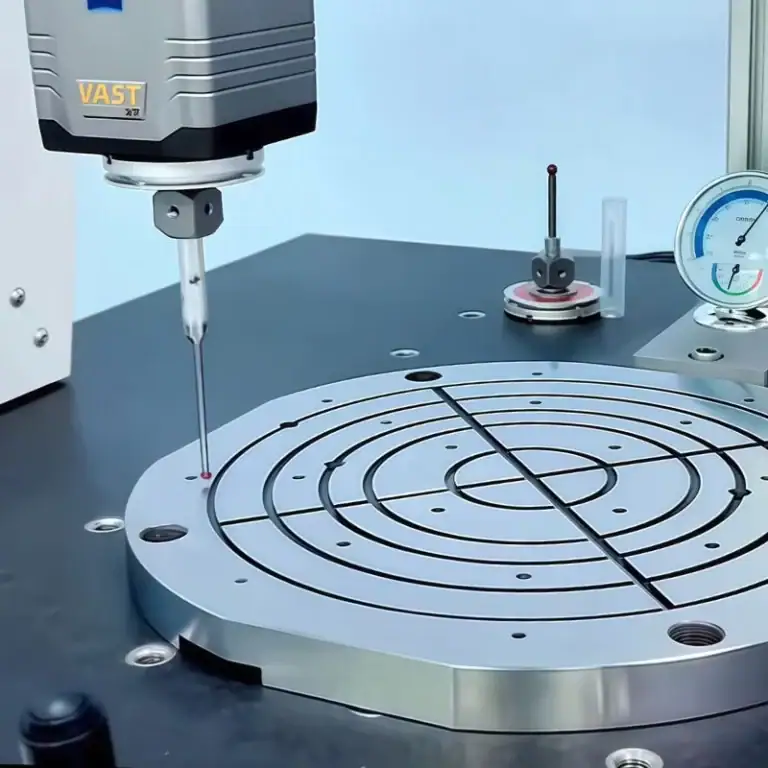
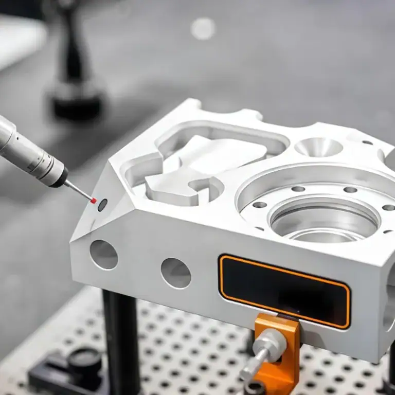
Surface roughness must be measured using a method appropriate to the feature and specification. Contact profilometers are common in machining inspection, while optical systems can measure delicate, very small, or complex surfaces without touching them. Sampling conditions and measurement direction can significantly affect the reported value.
Contact Profilometers
A contact profilometer moves a stylus across the surface.
The stylus follows the microscopic profile, and the instrument calculates parameters such as Ra or Rz.
This method is widely used because it is practical, well established, and suitable for many machined metal surfaces.
However, very soft surfaces, narrow grooves, or delicate coatings may not be ideal for stylus contact.
Optical And Non-Contact Measurement
Optical systems use light rather than a physical stylus to measure surface topography.
They can be useful for very small features, soft materials, complex shapes, or cases where contact might damage the surface.
Measurement results can depend on reflectivity, surface slope, optical method, and data processing, so the method should match the specification.
Sampling Length And Evaluation Length
A profilometer does not simply measure one arbitrary short line.
Sampling and evaluation lengths determine which surface wavelengths are included in the calculation.
If the length is inappropriate, the reading may include too much waviness or fail to capture representative roughness.
That is why surface texture specifications and measurement standards must be considered together.
Measurement Direction And Surface Lay
Measurement should normally cross the dominant lay rather than run parallel to it when the goal is to capture the primary surface irregularities.
Measuring in different directions can produce different Ra values on the same surface.
For directional milling or turning marks, this difference can be significant.
Common Surface Roughness Measurement Errors
Dirty surfaces, scratches, oil, incorrect stylus direction, unstable fixturing, wrong filtering settings, and inappropriate evaluation lengths can all distort results.
Another common mistake is checking only one convenient location on a large surface.
For critical parts, the measurement location and direction should be defined consistently.
What Factors Affect Machining Surface Roughness?
Machining surface roughness is controlled by the complete cutting system rather than a single parameter. Feed, speed, tool geometry, wear, depth of cut, rigidity, coolant, workholding, and material behavior interact with one another. Improving finish therefore requires identifying the dominant cause rather than changing settings randomly.
Feed Rate And Tool Path Spacing
Feed has a direct influence on the spacing of tool marks.
In turning, higher feed per revolution generally increases the theoretical profile height produced by the tool nose.
In milling, step-over and feed per tooth affect scallop spacing and surface pattern.
Reducing feed can improve finish, but excessively low feed may cause rubbing rather than clean cutting.
Cutting Speed And Spindle Speed
Cutting speed influences chip formation, temperature, and built-up edge.
Increasing speed within a suitable range can improve finish for some materials because the cutting edge shears material more cleanly.
But excessive speed increases heat and tool wear, which can make the finish worse.
The correct speed depends on material, tool coating, cutter diameter, and coolant strategy.
Depth Of Cut And Finishing Allowance
Heavy cutting forces during roughing can create deflection and vibration.
A controlled finishing allowance allows the final pass to remove a consistent amount of material.
If too little stock remains, the tool may rub. If too much remains, the finishing pass may experience unnecessary cutting force and deflection.
Tool Geometry And Cutting Edge Radius
Tool nose radius, rake angle, edge preparation, flute geometry, and insert style all influence the final texture.
A larger nose radius can improve turning finish at a given feed, but it can also increase radial cutting forces.
For thin or flexible parts, those additional forces may cause vibration or dimensional error.
Tool Wear And Built-Up Edge
A worn tool no longer cuts with the geometry assumed during process planning.
Edge wear increases cutting force and can tear the material.
Built-up edge occurs when workpiece material adheres to the tool and periodically breaks away, producing an irregular surface.
Monitoring tool condition is therefore essential when roughness requirements are tight.
Machine Rigidity, Vibration, And Chatter
A stable cutting system is necessary for a consistent finish.
Long tool overhang, weak fixtures, flexible workpieces, spindle runout, or insufficient machine rigidity can produce vibration.
Severe vibration creates chatter marks that may remain visible even if average Ra appears acceptable in selected locations.
Workpiece Material And Material Condition
Different materials form chips differently.
Free-machining aluminum and brass generally produce cleaner surfaces than gummy or work-hardening alloys under comparable conditions.
Heat treatment, hardness, inclusions, fiber reinforcement, and residual stress can also change the machining response.
How Do Milling And Turning Affect Surface Roughness?
Milling and turning can achieve similar Ra values, but they create different surface patterns. Tool motion, cutter engagement, feed direction, and part rotation determine the lay and visual appearance, which may affect function even when the measured roughness is similar.
CNC Milling Surface Roughness
Milling creates intermittent cuts as individual teeth enter and leave the material.
Face milling can generate circular or arcing tool marks, while side milling creates different directional patterns.
Runout between cutter teeth can cause one insert to cut more deeply than the others, reducing surface consistency.
CNC Turning Surface Roughness
Turning produces a helical surface pattern as the part rotates and the tool feeds along the axis.
Feed rate and tool nose radius strongly influence the theoretical finish.
Stable workholding and low spindle runout are important because vibration or part deflection can create periodic marks around the diameter.
Ball End Milling And Cusp Height
Ball end mills are commonly used for curved three-dimensional surfaces.
Because adjacent toolpaths overlap, small scallops or cusps remain between passes.
Reducing step-over decreases cusp height and improves finish, but it also increases machining time dramatically.
This is an important cost consideration in molds, aerospace surfaces, and complex five-axis parts.
Tool Marks And Surface Lay Differences
Different toolpaths can achieve similar average roughness but leave different directional patterns.
A one-direction finishing pass may produce a consistent lay, while cross-hatched or multi-directional passes can create a different visual and functional surface.
The best approach depends on whether appearance, sealing, friction, or coating performance is most important.
Why The Same Ra Can Look Different After Different Processes
Ra averages profile deviations.
It does not describe spacing, lay, waviness, or every individual defect.
As a result, a turned surface, ground surface, and milled surface can all measure around the same Ra while looking and behaving differently.
This is one reason functional surfaces should not be specified using Ra alone when other texture characteristics matter.
How To Improve Machined Surface Roughness
Improving surface finish starts with stable cutting. A sharp tool, rigid setup, controlled finishing allowance, suitable feed and speed, and good chip evacuation usually provide more benefit than simply reducing feed. Secondary processes should be added only when machining alone cannot economically achieve the required surface.
Reduce Feed During Finishing
A lower finishing feed reduces theoretical tool-mark height in many turning and milling operations.
However, feed should remain high enough for the cutting edge to shear material instead of rubbing.
Very low feed with a honed or worn tool can increase heat and create a smeared surface.
Use Sharp And Stable Cutting Tools
Finishing tools should have controlled geometry and minimal wear.
Dedicated finishing inserts or end mills are often more predictable than using a heavily worn roughing tool for the final pass.
Tool balance and runout also become increasingly important as surface requirements become tighter.
Minimize Tool Overhang And Chatter
Shorter tool overhang increases rigidity.
Fixtures should support the workpiece close to the cutting zone, particularly for thin walls or long shafts.
If chatter is present, lowering feed alone may not solve it. Spindle speed, tool length, engagement, workholding, or cutter geometry may need to change.
Optimize Speed, Depth Of Cut, And Coolant
Finishing parameters should be matched to the material.
A controlled depth of cut keeps the tool engaged consistently.
Coolant or air blast can remove chips before they are recut, reduce thermal instability, and prevent chips from scratching the finished surface.
Add A Dedicated Finishing Pass
Separating roughing and finishing improves process control.
Roughing removes most material quickly, while the finishing pass uses lower cutting load and more consistent stock.
This also allows a different tool to be selected specifically for surface quality.
Use Grinding, Honing, Lapping, Or Polishing When Required
Some finishes are difficult or uneconomical to achieve by milling or turning alone.
Grinding can improve dimensional control and finish on hardened parts.
Honing is useful for precision bores, while lapping and polishing can achieve very fine surfaces.
The secondary process should be chosen according to both roughness and geometry.
How To Choose The Right Surface Roughness For A CNC Part
The correct surface roughness is the least demanding finish that still satisfies the part’s function. Specifying an unnecessarily low Ra can increase machining time, tooling cost, inspection effort, and lead time without improving performance.
General Structural And Non-Critical Surfaces
Brackets, internal structural faces, and hidden surfaces often do not require extremely fine finishes.
A normal machined surface may be sufficient if the area does not seal, slide, locate, or carry a critical coating.
Reducing unnecessary finish requirements on these surfaces can save substantial cycle time.
Mating And Sliding Surfaces
Mating and sliding surfaces require more careful selection.
If the surface is too rough, high points may cause wear or inconsistent contact.
If it is excessively smooth, some lubricated interfaces may retain less oil.
The correct texture depends on material pair, load, speed, and lubrication.
Sealing Surfaces
Sealing faces may require both controlled roughness and controlled lay.
A surface can have a low Ra yet still leak if machining marks create continuous paths across the seal.
Flatness, waviness, and surface direction may therefore be just as important as average roughness.
Shafts, Bearings, And Rotating Components
Bearing seats and rotating shafts often require controlled surface texture because roughness influences fit, wear, contact stress, and installation.
Surface requirements should match the bearing or seal manufacturer’s functional recommendations rather than being selected from appearance alone.
Cosmetic And Coated Surfaces
Visible surfaces may need consistent tool marks even if the Ra requirement is not extremely low.
Coated or anodized surfaces can also show machining defects after finishing.
When appearance matters, the machining strategy should control not only Ra but also toolpath direction and consistency.
Match Ra To Function Instead Of Appearance Alone
The best roughness value is not the lowest number.
A functional surface requirement should be tied to sealing, wear, sliding, fatigue, appearance, or coating needs.
If no functional reason exists for Ra 0.8 instead of Ra 3.2, the tighter requirement may simply add cost.
How Does Surface Roughness Affect CNC Machining Cost?
Lower Ra requirements usually increase cost because they reduce process freedom. The manufacturer may need slower finishing passes, additional tools, more stable fixtures, secondary finishing, and more detailed inspection.
Why Lower Ra Values Increase Cycle Time
Improving finish often requires lower feed and smaller step-over.
On large or complex surfaces, these changes significantly increase toolpath length and machine time.
Five-axis freeform surfaces are particularly sensitive because a small reduction in step-over can multiply the number of finishing passes.
Additional Tooling And Finishing Operations
A normal milling cutter may satisfy Ra 3.2, while a finer requirement may need dedicated inserts or an additional grinding operation.
Special polishing and lapping also add manual or machine time.
Each extra process introduces handling, setup, and quality-control cost.
Inspection And Measurement Requirements
Loose surface requirements may be confirmed visually or with standard production checks when contract requirements permit.
Critical roughness values generally require a calibrated profilometer or appropriate optical system.
If multiple faces require measurement, inspection time increases accordingly.
When A Tighter Surface Finish Adds Little Functional Value
Specifying the same fine finish on every surface is rarely economical.
An internal pocket that never contacts another component may not need the same Ra as a sealing face.
Separating critical surfaces from ordinary machined areas allows manufacturing effort to be concentrated where it actually creates value.
What Are Common Machined Surface Finish Problems?
Poor surface finish usually has a recognizable cause. Tool marks, chatter, scratches, built-up edge, and inconsistent texture can often be traced to tooling, workholding, chips, vibration, or unstable cutting conditions.
Visible Tool Marks
Regular tool marks can result from excessive feed, large step-over, cutter runout, or insufficient finishing passes.
Some tool marks are normal and acceptable if they remain within the specified texture.
The problem arises when they exceed roughness requirements or interfere with function.
Chatter And Vibration Patterns
Chatter creates repeating waves or marks that are often visible without measurement equipment.
Possible causes include long tool overhang, weak fixtures, flexible components, poor spindle speed selection, or unstable cutter engagement.
Because chatter is a system-level problem, changing only one cutting parameter may not solve it.
Scratches And Built-Up Edge Damage
Loose chips trapped between the tool and surface can create scratches.
Built-up edge can periodically break away and tear the workpiece surface.
Improved chip evacuation, correct cutting speed, suitable coolant, and sharp tooling can reduce these defects.
Inconsistent Roughness Across One Surface
A large face may measure differently from one location to another because cutter engagement, tool deflection, runout, or material hardness changes.
Fixture distortion can also alter the cutting condition across the surface.
Consistent roughness requires consistent tool engagement and stable machine geometry.
Surface Roughness Outside Drawing Requirements
If a measured value exceeds the requirement, reworking the part may not always be simple.
Additional polishing can change dimensions, edges, or surface geometry.
The best approach is to control roughness during process planning rather than treating it only as a final inspection problem.
What Are Common Mistakes When Specifying Surface Roughness?
Design errors can increase machining cost just as easily as process errors. The most common problems are specifying unnecessarily low Ra values, using the same requirement everywhere, confusing roughness parameters, and ignoring how the surface will actually be measured.
Specifying A Lower Ra Than The Function Requires
A designer may choose Ra 0.8 because it appears more precise than Ra 3.2.
If the surface is only a noncritical mounting face, the tighter value may provide no functional improvement.
The result is longer cycle time and potentially unnecessary secondary finishing.
Treating Ra And Rz As Direct Equivalents
Ra and Rz measure different profile characteristics.
They should not be exchanged using a fixed conversion unless the customer and supplier have agreed on an appropriate engineering basis.
If the drawing specifies Rz, the process and measurement plan should control Rz.
Applying The Same Roughness To Every Surface
A blanket roughness requirement forces the manufacturer to finish surfaces that may have no functional need.
A better drawing identifies critical sealing, sliding, bearing, and visible surfaces separately while allowing normal machining on less important features.
Ignoring Surface Lay And Machining Direction
A low Ra value alone does not guarantee a suitable sealing or sliding surface.
Directional grooves can influence fluid leakage, friction, and wear.
If direction matters functionally, the drawing should communicate that requirement.
Specifying Roughness Without Considering Measurement Method
Some surfaces are difficult to access with a stylus.
Very small grooves, deep pockets, curved surfaces, and delicate materials may require alternative measurement methods.
The specified texture should therefore be realistically measurable on the finished part.
FAQs
Does Anodizing Change The Surface Roughness Of A Machined Aluminum Part?
Yes, anodizing can change the final surface texture because the oxide layer follows and can modify the underlying machined surface. If roughness is functionally critical after anodizing, the drawing should state whether the requirement applies before or after finishing.
Can A Low Ra Value Guarantee A Leak-Free Sealing Surface?
No. Sealing also depends on flatness, waviness, lay direction, gasket type, contact pressure, and defects. A low Ra value alone does not guarantee sealing performance.
Should Surface Roughness Be Specified Before Or After Coating?
The drawing should clearly state which condition is controlled. Coating, plating, polishing, or blasting can change the final surface, so the required measurement stage should match the functional condition of the part.
What If A Surface Cannot Be Reached By A Contact Profilometer?
An optical or other non-contact measurement method may be more suitable. The manufacturer and customer should agree on the method, measurement location, and acceptance criteria before production when access is limited.
Conclusion
Machined surface roughness is not simply a cosmetic value. Ra, Rz, surface lay, waviness, tool marks, and measurement conditions all influence how a finished part performs. The most effective approach is to specify roughness according to function, then select machining parameters, tooling, finishing operations, and inspection methods that achieve that requirement consistently without adding unnecessary process cost.
At TiRapid, we provide precision CNC machining and manufacturing services for prototypes and production parts. Our team combines controlled milling and turning, practical finishing strategies, dimensional inspection, and surface-quality verification to help customers achieve the required finish while balancing part performance, machining efficiency, and cost.