
Impellers are typical complex-surface components with narrow spaces between blades and significant curvature changes, requiring high levels of tool orientation control and five-axis synchronization accuracy. In actual CNC milling, overcutting is usually caused by a combination of factors, including toolpath planning, tool dimensions, machine movement, stock allowance, and workholding conditions. Once overcutting occurs at the leading edge, trailing edge, or hub area of a blade, it can not only affect aerodynamic performance but may also result in the entire part being scrapped. Therefore, it is essential to identify machining risks in advance.
Toolpath Planning Is an Important Cause of Impeller Overcutting
Impellers have complex structures, and the tool must continuously adjust its position and orientation within limited spaces. The quality of the CAM toolpath directly affects the final machining result.
Excessive Changes in Tool Axis Orientation
Tool axis control is a key aspect of five-axis milling. The following issues require particular attention:
- If the tool axis changes too quickly in areas where blade curvature varies, tool orientation may become unstable.
- Excessive changes in tool axis orientation between adjacent toolpaths may cause the actual cutting area to deviate from the theoretical trajectory.
- Improper control of the tool inclination angle near the leading and trailing edges of the blades can increase the risk of local interference.
- When the tool axis changes abruptly, the tool’s side cutting edge or holder may accidentally contact the blade.
Impeller machining should not focus only on the tool tip trajectory; the orientation changes of the entire tool must also be checked.
Improper Toolpath Spacing
Toolpath spacing affects surface residual stock and tool motion stability. When the step-over is too large, the residual stock on the surface may become uneven. When the step-over does not match the blade curvature, the tool trajectory may become abnormal. Insufficient local finishing allowance may increase the risk of the tool cutting directly into the workpiece. Toolpath density should be adjusted according to blade curvature, machining stage, and accuracy requirements rather than applying identical parameters to all areas.
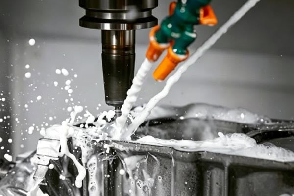
Interference Between the Tool and Blade Structure Can Easily Cause Overcutting
The spacing between impeller blades is limited. Tool dimensions, holder geometry, and tool overhang all affect the actual machining space, so tool selection must match the part structure.
Excessive Tool Diameter
When the tool diameter is too large, even if the tool tip trajectory meets theoretical requirements, the tool body may still interfere with adjacent blades. Typical problems include:
- When the blade spacing is narrow, the side of the tool can easily contact adjacent blades.
- In deep cavity areas, the limited space makes it difficult for large-diameter tools to maintain a safe clearance.
- The tool body may interfere with the workpiece even though no abnormality appears in the tool tip trajectory shown in the program.
- Local blade thinning may occur, and severe interference may directly result in overcutting.
Tool diameter should be selected comprehensively according to blade spacing, machining depth, and surface structure, rather than considering only tool rigidity or machining efficiency.
Excessive Tool Overhang
To reach deep blade areas, the tool usually needs to maintain a certain overhang. However, excessive overhang reduces overall tool rigidity and creates the following risks:
- The tool may deflect easily under cutting forces.
- Vibration and trajectory deviations may occur during high-speed machining.
- Changes in tool orientation may amplify actual cutting errors.
- Insufficient tool rigidity may also cause chatter marks or dimensional abnormalities on the blade surface.
A balance should be achieved between machining depth, tool accessibility, and tool rigidity, while unnecessary tool overhang should be minimized.
Five-Axis Machine Motion Errors May Also Cause Overcutting
Even when the CAM program has no obvious problems, differences may still exist between the actual machine motion and the theoretical model. These errors can be amplified during complex-surface machining.
Insufficient Rotary-Axis Positioning Accuracy
Five-axis machines rely on the coordinated movement of rotary and linear axes to machine complex surfaces. Insufficient rotary-axis accuracy may lead to the following problems:
- Positioning errors may cause the actual tool tip position to deviate from the theoretical trajectory.
- Backlash may cause motion errors in areas where the axis reverses direction.
- Machine geometric errors may affect tool orientation and blade profile accuracy.
- Minor rotary-axis deviations may be amplified in complex-surface areas.
The geometric accuracy, rotary-axis calibration status, and maintenance condition of five-axis equipment have a significant impact on impeller machining quality.
Mismatched Multi-Axis Synchronized Motion Speeds
When linear and rotary axes move at high speed simultaneously, insufficient control-system parameters or machine dynamic performance may cause motion-following errors. Common symptoms include slight deviations in the tool tip trajectory, local dimensional abnormalities on the blades, overcutting or undercutting in high-curvature areas, and unsmooth tool orientation changes caused by unsynchronized axis motion. The synchronized motion speed, acceleration, and feed parameters should be controlled according to machine performance to prevent the motion requirements from exceeding the actual response capability of the equipment.
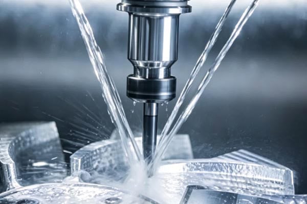
Stock Allowance and Workholding Conditions Should Not Be Overlooked
During impeller machining, the initial stock condition affects the actual tool engagement, while workholding stability also changes the position and deformation of the workpiece during cutting.
Uneven Stock Allowance Distribution
If significant differences exist in the stock allowance across different areas of the blank, the cutting load on the tool will also change accordingly. The main risks include:
- Excessive local stock may cause a sudden increase in tool load.
- Elastic tool deformation under cutting forces may cause the actual trajectory to deviate from the theoretical path.
- Excessive cutting forces can easily cause vibration.
- Dimensional abnormalities may occur at blade edges and thin-wall areas.
Before finishing, roughing and semi-finishing should be properly controlled to achieve a uniform stock distribution and create favorable conditions for stable subsequent cutting.
Insufficient Workholding Rigidity
Because impellers have complex structures, improper workholding may cause slight displacement or local deformation during machining. Typical problems include:
- Thin-wall blades may undergo elastic deformation under cutting forces.
- Unstable workpiece positioning may cause the machining datum to shift.
- Insufficient workholding support may amplify vibration in blade areas.
- After the workpiece shifts, actual overcutting may occur even if the tool follows the correct program.
Proper workholding, positioning, and auxiliary support can provide a stable foundation for five-axis CNC milling and reduce the risk of workpiece deformation and displacement.
How to Reduce the Risk of Overcutting in Five-Axis Impeller Milling
Impeller machining requires a complete control process covering programming, tooling, equipment, and quality inspection.
Perform a Complete Tool Interference Check Before Machining
Before formal machining, CAM software should be used to simulate the motion relationship between the tool, holder, spindle, and workpiece. The following checks should be completed:
- Check areas prone to interference, such as the leading edge, trailing edge, hub, and blade root.
- Verify the tool body envelope under different tool axis orientations.
- Check whether the tool holder and spindle collide with the blades or hub.
- Observe tool motion during direction changes, approach and retract movements, and operations in narrow areas.
- Check the complete tool model rather than viewing only the tool tip trajectory.
Complete collision simulation can identify potential overcutting problems in advance and provide a reliable program foundation for formal machining.
Optimize the Tool Axis and Toolpath According to Blade Curvature
For areas with significant curvature changes, smoother tool axis strategies can be adopted, and differentiated machining parameters can be set for different regions:
- Increase toolpath density appropriately in high-curvature areas.
- Reduce sudden changes in tool axis orientation.
- Control the safety distance between the tool and the blades.
- Adjust feed rates and cutting depths according to different blade areas.
- Apply more refined machining strategies to the leading edge, trailing edge, and hub areas.
Optimizing the tool axis and toolpath according to blade curvature can improve tool motion stability on complex surfaces and reduce the risk of local overcutting.
Verify Machining Results Through Actual Inspection
Program simulation cannot completely replace actual inspection. After the first part is machined, the results should also be verified through inspection methods:
- Use coordinate measuring machines to measure critical dimensions and blade profiles.
- Use in-process inspection to check blade thickness and positional deviations.
- Pay particular attention to the leading edge, trailing edge, and hub connection areas.
- Record and analyze the inspection results.
- Correct the toolpath, tool compensation, and machining parameters based on the inspection results.
Actual inspection can promptly identify deviations between the program and the machining results, improving the stability of subsequent batch production.
Conclusion
Local cutting abnormalities during impeller machining are often the result of multiple process conditions acting together and cannot be resolved solely through software programming. For these high-difficulty complex-surface components, a complete quality control plan should be established by combining tool specifications, orientation changes, equipment condition, simulation verification, and finished-part inspection. TiRapid can develop appropriate machining strategies based on part geometry, material properties, and tolerance requirements, reducing blade damage while improving production efficiency, dimensional consistency, and continuous manufacturing capability.
















