CNC turning tolerances are essential to component assembly, operational performance, and manufacturing costs. For businesses sourcing precision shafts, metal sleeves, connectors, threaded components, and automation equipment parts, setting appropriate dimensional tolerances helps manufacturers develop suitable machining strategies, reduce unnecessary precision operations, and improve batch consistency. Tolerances that are too loose may fail to meet assembly and functional requirements, while unnecessarily tight tolerances can increase machining time, inspection costs, and scrap rates. Understanding how to determine CNC turning tolerances, identify influencing factors, and establish effective inspection procedures helps buyers evaluate custom CNC turning services and obtain precision components that meet engineering specifications.
How to Determine CNC Turning Tolerances
CNC turning tolerance refers to the permissible variation between a component’s actual dimension and its specified design dimension. Engineering drawings typically define tolerances through upper and lower dimensional limits, limit deviations, or standardized tolerance grades. After machining, a component must meet the specified dimensional tolerances as well as any requirements for geometry, position, surface finish, and assembly. Appropriate tolerance selection should consider the component’s function, material properties, mating relationships, and manufacturing capabilities rather than simply pursuing the highest possible precision.
Set Dimensional Tolerances According to Component Applications
Different components have different functional requirements, so their CNC turning tolerances may vary considerably. A standard support component may only require conventional installation dimensions, while a precision bearing shaft, locating shaft, or sealing sleeve may need tighter dimensional control. Designers should identify critical dimensions according to actual operating conditions instead of applying the same high-precision requirements to every feature.
- Precision shafts: Shaft diameters, shoulder lengths, and mating dimensions affect rotational accuracy and assembly performance. For shafts that fit bearings, bushings, or couplings, critical journal tolerances should be clearly specified. Roundness, cylindricity, and circular runout should also be evaluated according to functional requirements. Slender shafts require additional consideration of deflection and clamping deformation to prevent dimensional changes after the workpiece is removed from the machine.
- Metal sleeves and bushings: Inner diameters, outer diameters, wall thicknesses, and concentric relationships affect fit and positioning accuracy. Thin-walled sleeves can deform elastically during clamping and partially recover after the fixture is released. Controlling clamping pressure, optimizing the machining sequence, and rechecking dimensions after unclamping can help reduce these effects.
- Threaded components: Thread specifications, tolerance classes, effective thread lengths, and entry chamfers should be defined according to the design requirements. Checking the external diameter alone does not confirm thread conformity. Suitable thread gauges or other specified inspection methods should be used to verify the thread.
- Sealing connectors: Sealing surfaces, mating bores, and related shoulders must meet dimensional and surface requirements appropriate to the sealing design. Components used in pressurized systems or fluid connections may require additional evaluation of sealing geometry, assembly conditions, and operating requirements.
Clearly identifying the functional requirements of each component allows designers to distinguish critical dimensions from standard structural features. Complete tolerance specifications help CNC machining suppliers select appropriate tools, fixtures, and inspection methods while reducing rework caused by unclear drawings.
Distinguish General Tolerances from Precision Tolerances
General tolerances are commonly used for structural dimensions that have limited influence on assembly or operating performance. They simplify drawing specifications and inspection procedures. Precision tolerances apply to critical features that directly affect fit, positioning, sealing, or motion performance. Selection should follow applicable engineering standards, product design requirements, and actual machining capabilities.
General tolerances may be suitable for ordinary external dimensions, while shaft-and-bore fits, precision locating features, and rotating assemblies may require explicit dimensional and geometric tolerances. Dimensional tolerances control variations in length or diameter, whereas geometric tolerances control form, orientation, location, and runout. For example, a precision shaft may meet its diameter tolerance but still cause rotational problems if its roundness or runout is unacceptable. Similarly, controlling the outer diameter of a thin-walled component does not necessarily guarantee uniform wall thickness or the required relationship between its inner and outer surfaces.
Evaluate How Tolerances Affect Machining Costs
Tighter tolerances generally require more stable machine conditions, suitable cutting tools, precise workholding, and stricter inspection procedures. Manufacturers may need additional finishing operations, shorter inspection intervals, or higher-precision measuring equipment, all of which can affect part pricing and delivery time.
- Identify critical dimensions: Maintain the necessary precision for features that directly affect fit, positioning, sealing, or operating performance. Use appropriate tolerances for noncritical dimensions to avoid unnecessary machining.
- Provide complete engineering drawings: Include material grades, dimensional tolerances, surface roughness, geometric tolerances, and relevant technical notes to reduce quotation uncertainty.
- Assess manufacturing challenges in advance: Thin walls, slender geometries, deep bores, and narrow grooves may require specialized tooling, workholding, and inspection methods. Evaluating these challenges before production helps prevent unexpected manufacturing difficulties.
Appropriate tolerance allocation allows businesses to meet functional requirements without incurring unnecessary machining and inspection costs. A manufacturability review with the CNC turning supplier can also establish realistic quality expectations before production begins.
What Factors Affect CNC Turning Accuracy?
CNC turning can provide consistent dimensional repeatability, but final accuracy still depends on machine condition, material properties, workpiece geometry, tool wear, and machining parameters. Even when the same CNC program is used, differences in material batches, clamping conditions, or tool condition may cause dimensional variations. Developing a process that matches the component’s characteristics is essential for maintaining dimensional tolerances.
Machine Accuracy and Thermal Stability
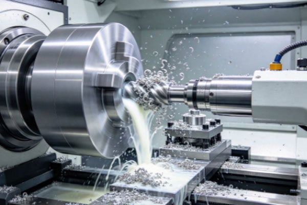
The condition of the spindle, guideways, turret positioning system, and overall thermal stability of a CNC lathe can influence final dimensions. During continuous operation, temperature changes in the spindle, cutting tools, and machine structure may cause minor thermal deformation, resulting in gradual dimensional drift. For high-precision components, manufacturers should maintain stable machine conditions and apply warm-up procedures, tool compensation, or in-process measurement when necessary.
Machine capabilities must also match the dimensions and geometry of the workpiece. Precision internal bores, narrow grooves, and close-tolerance mating surfaces may require specialized tools, precision fixtures, and tighter process control. When evaluating a CNC turning supplier, buyers should consider not only machine specifications but also maintenance practices, machining experience, and inspection capabilities.
Material Properties and Workpiece Deformation
Aluminum alloys, stainless steel, carbon steel, and copper alloys have different hardness levels, toughness, thermal conductivity, and cutting characteristics. These differences influence cutting forces, heat distribution, and dimensional stability after machining. Some metal components may release internal stresses after substantial material removal, causing changes in shape.
Thin-walled sleeves can deform elastically under clamping pressure and partially recover after unclamping. Slender shafts may deflect under cutting forces, causing the finished diameter to deviate from its target value. To address these challenges, manufacturers can optimize clamping pressure, reduce tool overhang, use tailstock or additional support, and arrange roughing, semi-finishing, and finishing operations appropriately. For critical components, dimensions may also be rechecked after unclamping to confirm conformity in the free state.
Tool Wear and Cutting Parameters
Cutting edges gradually wear during machining, changing cutting forces, temperatures, and surface conditions. If tool offsets are not adjusted or inserts are not replaced at appropriate intervals, dimensions may gradually move outside the specified tolerance range. Cutting speed, feed rate, and depth of cut also influence workpiece deformation and machining stability. Unsuitable parameters may cause vibration, surface defects, or dimensional variation.
- Manage tool life: Establish replacement rules based on material type, machining quantity, and historical wear data. For critical dimensions, inspect tool condition before excessive wear causes repeated dimensional deviations.
- Control machining allowances: Roughing removes most of the excess material, while finishing requires a stable and suitable allowance. Excessive allowance may increase cutting loads, whereas insufficient allowance may prevent the correction of dimensional or geometric errors from previous operations.
- Optimize cutting parameters: Adjust cutting speed, feed rate, and depth of cut according to the material, tooling, and workpiece rigidity. For slender shafts and thin-walled components, controlling cutting forces is often more important than maximizing material removal rates.
- Record dimensional changes: Use first-article inspection and in-process measurements to monitor dimensional trends. If dimensions continue shifting in one direction, investigate tool wear, thermal conditions, clamping, and cutting parameters.
Consistent tool management and cutting parameter control help reduce dimensional drift during batch production. Manufacturers should refine their processes based on actual machining results rather than relying exclusively on parameters established during initial trials.
How to Inspect and Control CNC Turning Tolerances
Appropriate tolerance specifications must be supported by reliable inspection procedures. Manufacturers should select measuring instruments according to component geometry, dimensional range, and precision requirements, then establish first-article inspection, in-process sampling, and final inspection procedures. For precision shafts, thin-walled sleeves, and threaded connectors, inspection should cover not only individual dimensions but also the critical form, position, and mating characteristics specified in the engineering drawings.
Select Suitable Dimensional Measuring Instruments
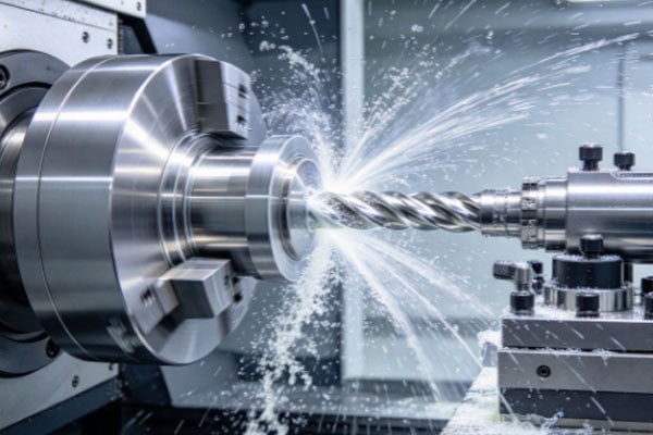
Different measuring instruments have different measurement ranges, accuracy levels, and applications. The selected instrument must be capable of verifying the specified tolerance while accounting for calibration status, measurement methods, and environmental conditions.
- Outside micrometers: Suitable for measuring precision shaft diameters, external cylindrical surfaces, and other critical external dimensions. Before measurement, clean the workpiece and measuring faces, confirm the instrument’s calibration status, and measure at the specified locations.
- Vernier calipers: Useful for general dimensional checks and preliminary inspection, but they may not be suitable for verifying very tight tolerances. More appropriate instruments should be selected for precision mating dimensions.
- Bore measuring instruments: Inside micrometers, bore gauges, and other suitable instruments can inspect precision internal diameters. Measurements at different depths and orientations can help identify dimensional variation or form errors.
- Thread gauges: Used to verify specified thread conformity. Go/no-go gauges should be applied according to the relevant thread standards and inspection requirements rather than relying on visual appearance alone.
- Coordinate measuring machines: Components with complex geometric relationships, multiple datums, or strict positional requirements may require coordinate measuring equipment. The measurement method should match the component geometry, drawing datums, and inspection specifications.
Instrument selection should not depend solely on display resolution. Actual measurement capability, repeatability, and operating conditions must also be considered. Using appropriate measuring equipment helps manufacturers determine whether parts meet the drawing requirements and reduces the risk of incorrect acceptance or rejection.
Establish First-Article Inspection and Batch Sampling
First-article inspection verifies whether the machining program, tool offsets, workholding method, and critical dimensions meet the drawing requirements. After the first article is approved, in-process sampling should be scheduled according to production volume, component risk, and customer specifications. Operations that are particularly sensitive to dimensional changes may require shorter inspection intervals. Critical features should also be revalidated after tool replacement, fixture adjustments, or program modifications.
Batch inspection records should include material information, drawing revisions, measurement results, instrument details, and the disposition of nonconforming parts. When measurements show a consistent dimensional shift, historical records can help identify possible relationships with tool wear, thermal changes, or clamping conditions. Detecting dimensional trends early allows corrective action before a large quantity of parts falls outside tolerance, reducing rework and scrap.
How to Choose a Reliable Precision CNC Turning Supplier
When selecting a custom CNC turning supplier, buyers should evaluate machining capabilities, quality management, inspection equipment, communication, and delivery reliability rather than comparing unit prices alone. The supplier must understand dimensional tolerances, geometric tolerances, material requirements, and surface finish specifications in the engineering drawings. Potential manufacturing risks should be identified before production begins.
- Verify machining capabilities: Confirm that the supplier has CNC lathes, tooling, and fixtures suitable for the component dimensions, materials, and tolerance requirements. Relevant experience with similar parts is also valuable.
- Review inspection procedures: Check whether the supplier performs first-article inspection and in-process sampling for critical dimensions and can provide dimensional reports or other agreed quality documents.
- Evaluate technical communication: The supplier should explain how special tolerances affect machining operations, measurement methods, and costs. If a drawing presents manufacturing challenges, the supplier should provide recommendations before production.
- Confirm batch delivery requirements: For recurring orders, clarify material batch management, program revision control, quality record retention, and delivery schedules to minimize variation between production batches.
A reliable CNC turning partner can evaluate drawing requirements before manufacturing, control critical dimensions during production, and verify component quality through measurement data. Buyers can reduce quotation discrepancies, rework, and delivery delays by providing complete drawings, identifying critical tolerances, and confirming inspection criteria in advance.
For businesses sourcing custom precision components, appropriate tolerance selection, suitable measurement methods, and consistent quality control help balance assembly accuracy, machining costs, and production efficiency. Working with a supplier that offers process reviews, precision machining, and inspection capabilities also establishes a stronger foundation for future batch orders.