Aluminum alloy components used in semiconductor equipment may look like simple mounting plates, support brackets, or structural parts with complex holes and slots, but machining them accurately takes careful planning. These components must remain lightweight while maintaining precise relationships between holes, flat surfaces, and mounting interfaces. Some also require anodizing or other surface treatments. Inconsistent machining accuracy can lead to assembly misalignment and even affect equipment performance. For semiconductor equipment manufacturing, an effective CNC machining solution must address material properties, machining efficiency, surface finish, and batch consistency to ensure custom components are ready for reliable use.
What Are the Main CNC Machining Challenges for Aluminum Alloy Semiconductor Components?
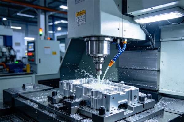
Aluminum alloys are lightweight and relatively easy to machine, making them common materials for semiconductor equipment structures. However, their machinability does not mean every component is easy to produce. Complex hole patterns, thin-wall structures, and large flat surfaces can all create dimensional challenges. Precision mounting components are particularly sensitive to datum selection and workholding stability.
How to Maintain CNC Machining Accuracy for Aluminum Semiconductor Parts?
Semiconductor components often contain multiple mounting holes, locating holes, stepped features, and connecting surfaces. Machining must control not only individual dimensions but also the positional relationships between features to meet drawing requirements.
- Precision hole machining: Control hole diameters, spacing, and positions to reduce alignment problems during assembly.
- Thin-wall machining: Manage clamping force and cutting loads to prevent deformation during machining and dimensional changes after unclamping.
- Large flat-surface machining: Plan roughing and finishing operations carefully to minimize flatness changes caused by residual stress release.
- Complex slot machining: Check tool length, cutting clearance, and chip evacuation conditions in advance to reduce chatter and localized overcutting.
The final quality of precision components often depends on how well these details are planned. Establishing clear locating datums, allocating suitable machining allowances, and checking dimensions after critical operations can reduce repeated adjustments and help parts meet semiconductor equipment assembly requirements.
How to Control Surface Finish on Aluminum Semiconductor Components?
Aluminum alloys offer good machining efficiency, but worn tools or unsuitable cutting parameters can still cause burrs, scratches, and uneven tool marks. For components requiring anodizing, the dimensional and appearance changes caused by surface treatment must also be considered in advance. Proper scheduling of finishing, deburring, and surface treatment helps achieve the required final condition without unexpected rework.
How to Reduce Assembly Errors in Custom Aluminum Components?
For semiconductor parts with multiple connecting surfaces and locating holes, poorly selected datums can cause individual operations to pass inspection while the assembled features remain misaligned. Critical mounting surfaces and mating dimensions should be defined before machining, with unnecessary re-clamping kept to a minimum. If the component must fit other precision parts, interface dimensions and acceptance requirements should also be confirmed in advance.
How to Select Materials and CNC Machining Processes for Aluminum Semiconductor Components?
Different aluminum alloy grades vary in strength, hardness, corrosion resistance, and machining behavior. Material selection should not be based on machinability alone. The alloy must suit the component’s intended use, while the tooling, machining sequence, and surface treatment process must be planned accordingly.
Which Aluminum Alloys Are Commonly Used in Semiconductor Equipment?
| Aluminum Alloy | Typical Applications | Key Machining Considerations |
| 6061 aluminum alloy | Mounting plates, brackets, equipment structures | Good machinability; control thin-wall deformation and surface treatment |
| 6063 aluminum alloy | Selected structural profiles and support components | Consider structural rigidity, dimensional requirements, and surface finish |
| 7075 aluminum alloy | High-strength connectors and load-bearing components | Control cutting parameters, material condition, and deformation |
The final material choice should follow the engineering drawings, strength requirements, and operating environment. Different grades have different properties, so machining difficulty alone should not determine the selection. If anodizing or another surface treatment is required, its impact on dimensions and tolerances should be confirmed before production.
How to Plan CNC Machining Operations for Aluminum Semiconductor Components?
Complex components typically require roughing, finishing, deburring, and inspection. A well-planned sequence can reduce the number of setups and help control dimensional changes in thin-wall areas and critical mounting surfaces.
- Roughing stage: Remove the main material allowance without unnecessarily finishing precision surfaces too early.
- Finishing stage: Focus on critical holes, locating surfaces, and mating features to meet dimensional and surface quality requirements.
- Post-processing stage: Complete deburring, cleaning, and specified surface treatments, then recheck critical dimensions after treatment.
For components with complex geometry or tight tolerances, evaluating tool accessibility, fixture design, and toolpaths in advance can reduce trial cuts and program adjustments.
What Information Is Needed for Custom CNC Machining of Aluminum Semiconductor Components?
Complete technical documentation makes machining requirements and production planning easier to assess. When requesting custom manufacturing, provide 2D engineering drawings or 3D models and clearly specify the alloy grade, critical tolerances, surface treatment, order quantity, and delivery schedule. For parts that mate with other components, identify locating datums and critical interfaces to avoid repeated revisions caused by incomplete information.
How to Ensure Consistent Quality in CNC Machining for Aluminum Semiconductor Components?
Passing prototype inspection does not guarantee that every part in a production run will remain within specification. Tool wear, fixture changes, and material batch variations can all affect machining results. Scheduling first-article inspection, in-process checks, and final inspection at appropriate stages helps identify problems early and reduces the risk of batch-wide rework.
What Inspection Items Are Required for Precision Aluminum Semiconductor Components?
| Inspection Item | Main Checks | Purpose |
| Dimensional accuracy | Overall dimensions, hole diameters, slot widths | Verify drawing tolerances |
| Positional accuracy | Hole spacing, hole locations, datum relationships | Ensure correct mounting positions |
| Geometric accuracy | Flatness, perpendicularity, and related tolerances | Check critical mating surfaces |
| Surface quality | Roughness, burrs, and scratches | Meet specified surface requirements |
| Surface treatment | Coating or anodized layer condition and post-treatment dimensions | Verify finishing requirements |
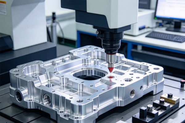
Inspection items should be defined by the engineering drawings and technical specifications. Maintaining records for critical dimensions makes production status easier to review and provides useful reference data for repeat orders.
How to Reduce Quality Variation During CNC Machining?
In-process inspection helps identify dimensional deviations before all parts are completed. Inspection checkpoints should be planned for features that are particularly sensitive to variation, including precision holes, thin walls, and large flat surfaces.
- Check critical hole diameters and spacing, including their positions relative to the locating datums.
- Recheck thin-wall components after unclamping to identify clamping deformation or springback.
- Monitor tool wear and cutting conditions, adjusting machining parameters when dimensional trends begin to change.
- After surface treatment, verify critical dimensions and appearance to ensure the finishing process has not affected assembly requirements.
Integrating inspection into the production workflow helps reduce batch variation and minimizes delivery delays caused by rework.
How to Move Aluminum Semiconductor Components from Prototyping to Batch Production?
The prototype stage should verify dimensions, mounting interfaces, and surface requirements. Once the part passes validation, the proven machining program, workholding method, and inspection criteria should be carried forward into production. When drawings are revised, confirming the latest revision and changes helps prevent discrepancies between prototype and production parts.
CNC machining for aluminum semiconductor components requires a balance of lightweight design, dimensional precision, surface treatment, and batch consistency. Defining the alloy grade, critical tolerances, and assembly interfaces in advance, then applying a suitable machining plan and in-process inspection, can reduce rework and improve component compatibility. TIRAPID provides CNC machining services for aluminum semiconductor equipment components, supporting custom manufacturing, prototype development, and batch production to help precision parts meet equipment assembly requirements reliably.