A turbine vane is a stationary aerodynamic component that directs hot, high-pressure gas toward rotating turbine blades. Its carefully shaped airfoil controls gas direction and velocity, allowing the turbine to extract energy efficiently. Because turbine vanes operate under severe thermal conditions, their design, material strength, cooling performance, and manufacturing accuracy directly influence engine reliability and service life.
This guide explains turbine vane functions, types, aerodynamic design, materials, cooling systems, and manufacturing methods. It also explores precision CNC machining, investment casting, protective coatings, thermal simulation, and quality inspection to help engineers understand how these critical components are designed and manufactured for demanding turbine applications.
What Is a Turbine Vane?
A turbine vane is a stationary airfoil-shaped component in a gas turbine that guides and accelerates hot gas before it reaches the rotating turbine blades. Unlike rotating blades, turbine vanes remain fixed relative to the engine casing and control the flow direction, pressure distribution, and inlet conditions required for efficient energy extraction.
Turbine vanes are usually arranged in circumferential rows between rotating blade stages. In the first turbine stage, the nozzle guide vanes receive high-temperature gas from the combustor. Later stationary rows redirect the flow leaving upstream rotors before it enters the following rotating stage.
A typical vane includes an aerodynamic airfoil, inner and outer platforms, and mounting features. Some designs also contain internal cooling passages and small surface holes. These features allow the component to maintain its aerodynamic profile while operating under changing temperatures and mechanical loads.
Although the terms are sometimes used interchangeably, a turbine vane is not the same as a compressor inlet guide vane. Compressor vanes manage incoming air before compression, whereas hot-section turbine vanes control combustion gases after the combustor. This article focuses on turbine-section stationary vanes.
How Does a Turbine Vane Work?
A turbine vane works by turning and accelerating hot gas through stationary passages so that it enters the rotating turbine blades at the intended angle and velocity. The vane converts part of the gas’s available pressure energy into kinetic energy, allowing the downstream rotor to extract useful mechanical work.
The operating principle depends on the relationship between the stationary vane row and the rotating blade row. Proper aerodynamic alignment helps reduce unnecessary flow losses and supports efficient power generation throughout the turbine.
Directing Hot Gas and Controlling Airflow
Hot gas leaving the combustor enters the stationary vane passages with a specific pressure, temperature, and flow direction. The curved vane surfaces create a controlled pressure distribution that turns the gas toward the downstream rotor. The required exit angle depends on the turbine-stage design.
As gas travels between adjacent vanes, the passage geometry influences its velocity and static pressure. In a nozzle guide vane row, the flow generally accelerates as pressure decreases. This process prepares the gas for energy extraction by the rotating blades rather than generating shaft power directly.
Poor flow guidance can produce separation, secondary flows, and additional aerodynamic losses. Engineers therefore evaluate inlet incidence, passage throat area, turning angle, and outlet conditions. These parameters determine how effectively the vane prepares the gas for the next rotating stage.
How Turbine Vanes Improve Engine Efficiency
Turbine vanes improve engine efficiency by delivering the gas to rotor blades at a suitable angle and velocity. Correct flow guidance supports the intended change in gas momentum across the rotor, helping convert the available gas energy into mechanical power with lower aerodynamic losses.
The vane’s performance is closely linked to the geometry of adjacent rotor blades. Excessive flow deviation or poorly matched blade angles can create losses even when individual components appear aerodynamically efficient. Stage-level analysis is therefore more useful than evaluating a single vane in isolation.
Improved turbine efficiency can reduce the fuel required for a given operating duty, depending on the complete engine cycle. However, turbine performance also depends on compressor efficiency, combustion conditions, cooling-air consumption, and operating load. Vane design contributes to efficiency but does not determine it alone.
What Are the Different Types of Turbine Vanes?
The main types of turbine vanes include nozzle guide vanes, intermediate stator vanes, and stationary vanes used in high-pressure and low-pressure turbine stages. Their classification depends on location, operating conditions, and aerodynamic function rather than on one universal blade shape.
Understanding vane types helps engineers identify the required temperature capability, structural design, and manufacturing method. The terms used in turbine engineering sometimes overlap, so it is important to distinguish component function from stage location.
Nozzle Guide Vanes and Turbine Stator Vanes
Nozzle guide vanes are the stationary airfoils positioned immediately upstream of a turbine rotor, particularly the first rotor following the combustor. They control flow turning and acceleration before the gas reaches the rotating blades. First-stage vanes experience especially demanding thermal conditions.
A stator blade is a broader term for a stationary aerodynamic blade. In a gas turbine, later stator rows guide gas from one rotor stage to the next. Their geometry is selected to match the changing pressure, velocity, and flow angle throughout the turbine.
The phrase turbine inlet guide vanes is sometimes used for stationary inlet components, but nozzle guide vane is generally the more specific term for the hot-gas nozzle row. Engineers should verify the exact location because compressor guide vanes and turbine nozzle vanes have different operating requirements.
High-Pressure and Low-Pressure Turbine Vanes
High-pressure turbine vanes operate in the turbine section immediately downstream of combustion. They typically experience very high gas temperatures and demanding thermal gradients. Their designs often incorporate advanced superalloys, protective coatings, and controlled cooling passages.
Low-pressure turbine vanes operate farther downstream, after part of the gas energy has already been extracted. Gas temperature and pressure are generally lower, although aerodynamic efficiency, structural loading, and component life remain important design considerations.
The difference affects manufacturing decisions. High-pressure vanes may require intricate cooling passages and specialized casting, while some lower-temperature designs can use simpler construction. Nevertheless, actual requirements depend on the engine architecture rather than stage designation alone.
Turbine Vane vs. Turbine Blade: Key Differences
A turbine vane remains stationary and controls gas direction, while a turbine blade is attached to a rotating disk and extracts energy from the gas. Both have aerodynamic profiles, but their mechanical loads differ because rotating blades also experience significant centrifugal forces.
Blade designs must manage rotor attachment stresses and dynamic behavior. Vanes are more strongly affected by casing support, pressure loading, thermal expansion, and local temperature gradients. Both components may require internal cooling, coatings, and highly controlled manufacturing.
| Feature | Turbine Vane | Turbine Blade |
| Movement | Stationary | Rotating |
| Main Function | Direct and accelerate gas | Extract energy and drive the rotor |
| Typical Mounting | Casing, carrier, or stationary segment | Rotating disk |
| Major Loads | Thermal gradients and gas pressure | Centrifugal, thermal, and aerodynamic loads |
| Critical Features | Airfoil, platforms, cooling passages | Airfoil, root, platform, and possible shroud |
The difference between these components is important when selecting materials, establishing tolerances, and planning inspections. Manufacturing requirements should follow the actual mechanical function rather than treating vanes and rotating blades as interchangeable parts.
Key Design Features of Turbine Vanes
Turbine vane design focuses on airfoil geometry, flow passage dimensions, mounting interfaces, sealing features, and structural strength. These features determine how accurately the component controls hot-gas flow while maintaining its shape and position under pressure and temperature changes.

Airfoil Geometry and Aerodynamic Performance
The turbine airfoil is the curved aerodynamic surface that controls the direction and acceleration of hot gas. Important geometric parameters include chord length, camber, thickness distribution, leading-edge radius, trailing-edge thickness, and the angle between the inlet and outlet flow.
The leading edge must accept the expected incoming flow without excessive incidence losses. The pressure and suction surfaces then guide the gas toward the trailing edge. Their shapes affect local acceleration, pressure distribution, and possible flow separation across the passage.
Engineers use aerodynamic analysis to evaluate these interactions before manufacturing. Blade-to-blade spacing and passage throat dimensions are particularly important because they influence gas flow capacity. Geometry changes must also consider manufacturing tolerances and coating buildup.
Vane Mounting, Sealing, and Structural Design
Turbine vanes require mounting features that hold the airfoil in its intended position without preventing necessary thermal movement. Depending on the engine, these features may include hooks, rails, platforms, locating surfaces, and interfaces with a turbine vane carrier.
The turbine shroud and surrounding casing components help define the hot-gas flow path and control leakage around the rotating and stationary parts. Sealing features must limit bypass flow while accommodating manufacturing variation and expansion during operation.
Structural design must also account for pressure loading, vibration, thermal stress, and creep. Finite element analysis helps identify stress concentrations around platform corners, fillets, and mounting features. These areas require careful geometric transitions and appropriate material properties.
Turbine Vane Cooling and Thermal Management
Turbine vane cooling uses internal air passages, surface film cooling, and protective thermal systems to keep component temperatures within acceptable limits. Cooling is essential because gas temperatures in advanced turbine stages may exceed the allowable continuous operating temperature of the underlying metal alloy.
The cooling system must protect the vane without consuming excessive compressor air. Engineers therefore examine cooling effectiveness, flow resistance, temperature gradients, and mechanical stresses together rather than optimizing cooling capacity alone.
Internal Cooling Channels and Film Cooling
Internal cooling passages carry relatively cool air through the vane structure to remove heat from the surrounding material. Depending on the design, the passages may use serpentine channels, impingement jets, ribs, or pin-fin structures to improve internal heat transfer.
Film cooling releases some turbine cooling air through small holes distributed across selected external surfaces. This air forms a cooler layer between the hot combustion gas and the vane material, reducing local heat transfer when the discharge conditions are properly controlled.
Cooling performance depends on hole position, flow direction, pressure difference, and coolant distribution. Excessive cooling-air consumption can reduce cycle efficiency, while insufficient flow leaves dangerous hot spots. The system must be evaluated across relevant operating conditions.
Thermal Stress and High-Temperature Challenges
Turbine vanes experience thermal stress because different regions heat and cool at different rates. Leading edges, trailing edges, internal walls, and mounting platforms can develop temperature differences that produce local expansion and mechanical strain.
Repeated startup and shutdown cycles can contribute to thermal fatigue. Long exposure to elevated metal temperatures may also promote creep, while uneven cooling can create local distortion. These effects are especially important around thin walls and abrupt geometry changes.
Engineers must therefore evaluate transient temperature conditions, not only steady-state operation. Material properties, wall thickness, cooling layout, and support conditions all affect the stress distribution. Controlling temperature gradients is often as important as reducing the maximum temperature.
Thermal Analysis and Coupled 1D/3D Simulation
Thermal analysis predicts how heat moves from the hot gas through the vane structure and into the internal cooling system. A conventional approach combines external computational fluid dynamics, simplified cooling-flow models, and three-dimensional solid heat-transfer calculations.
Coupled 1D/3D simulation integrates a one-dimensional cooling network with a three-dimensional thermal model. The network predicts coolant distribution and pressure losses, while the solid model evaluates local temperatures and conduction through the vane walls.
This approach supports design changes without requiring a fully detailed three-dimensional model of every cooling passage for every iteration. However, results still depend on accurate boundary conditions, material properties, and validation against experimental or higher-fidelity data.
Turbine Vane Materials and Protective Coatings
Turbine vanes are commonly made from nickel-based or cobalt-based superalloys, while selected advanced designs may use ceramic matrix composites. Protective coatings improve resistance to oxidation, corrosion, and heat transfer, allowing the component to operate more reliably under demanding thermal conditions.
Material selection must consider creep resistance, fatigue performance, thermal expansion, corrosion behavior, and compatibility with the coating system. The substrate and protective layers should be treated as an integrated engineering solution.
Nickel-Based Superalloys and Material Selection
Nickel-based superalloys are widely used in hot-section turbine components because they maintain useful mechanical properties at elevated temperatures. Grades such as René 80 and other application-specific alloys may be selected according to creep, oxidation, and fatigue requirements.
Cobalt-based alloys can also provide useful resistance to high-temperature oxidation and corrosion. The choice of turbine alloy depends on the local gas environment, component loading, expected temperature distribution, and manufacturing route rather than a single material property.
The development of single crystal turbine blades demonstrates the importance of controlling material microstructure. Directional solidification and single-crystal casting can reduce certain grain-boundary limitations. A pigtail selector, also called a grain selector, helps establish the desired crystal orientation during casting.
Thermal Barrier Coatings and Suspension Plasma Spray
Thermal barrier coatings reduce heat transfer into the underlying superalloy. A typical system combines a metallic bond coat with a ceramic topcoat, often based on yttria-stabilized zirconia. The coating must tolerate thermal cycling without premature cracking or separation.
Common application technologies include atmospheric plasma spraying and electron beam physical vapor deposition. Suspension plasma spray uses a liquid suspension containing fine particles to produce specialized coating structures and offers another process route for selected high-temperature components.
Gas turbine blade coating technology is also relevant to stationary vanes, although coating thickness and process parameters depend on component requirements. A successful coating must maintain adhesion, thermal durability, and compatibility with the underlying alloy.
Environmental Barrier Coatings for Ceramic Components
Environmental barrier coatings protect selected ceramic matrix composites against harmful reactions with combustion gases. Silicon-based ceramic materials can be vulnerable to water vapor and other aggressive species at high temperatures, making chemical protection essential.
Unlike conventional thermal barrier coatings, which primarily reduce heat transfer into metallic components, environmental barrier coatings focus on limiting environmental degradation of the ceramic substrate. Their performance depends on composition, density, adhesion, and resistance to thermal cycling.
These coatings are important in the development of lighter and higher-temperature turbine components. However, they require careful compatibility testing because coating defects, thermal expansion mismatch, or exposure to molten deposits can compromise long-term protection.
How Are Turbine Vanes Manufactured?
Turbine vanes are manufactured through a combination of precision casting, CNC machining, cooling-hole production, surface finishing, and quality inspection. Investment casting commonly forms complex airfoils and internal passages, while multi-axis CNC machining produces accurate mounting interfaces and accessible precision features.
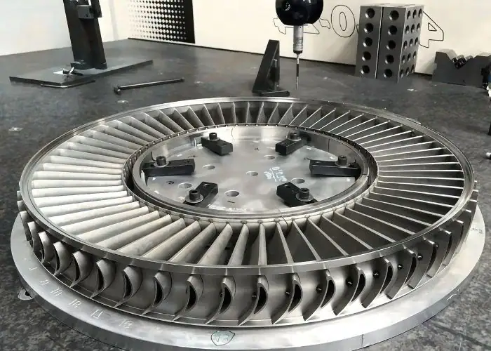
The manufacturing route depends on alloy, geometry, operating temperature, and production volume. Complex cooled vanes often require multiple processes because no single method can efficiently produce every internal feature and external surface to the required specification.
5-Axis CNC Machining for Precision Features
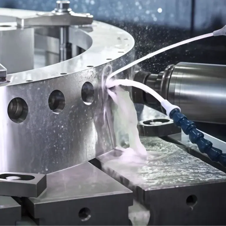
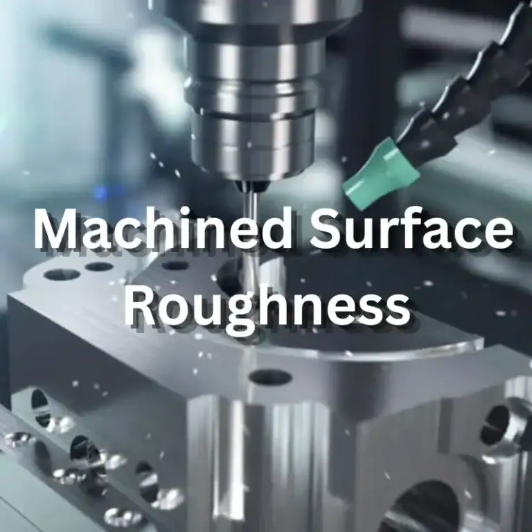
5-axis CNC machining is used to produce accurate mounting surfaces, platforms, locating features, and accessible airfoil geometry. CNC milling provides controlled tool positioning around complex surfaces, while suitable turning or other machining operations may be used for rotational features on related components.
Manufacturing begins with reviewing the CAD model, casting allowance, functional datums, and tool access. Stable fixtures must support the vane without distorting thin airfoil sections. Indexed or simultaneous 5-axis movements are selected according to the geometry and accessibility of each feature.
Roughing removes machining allowance, while finishing produces the required dimensional relationships and surface condition. Nickel-based superalloys create additional challenges because of cutting forces, heat concentration, and tool wear. Appropriate carbide tooling, controlled engagement, and CAM simulation help manage these risks.
Investment Casting for Complex Vane Geometry
Investment casting is widely used to produce complex turbine vane shapes from high-temperature alloys. A ceramic shell forms the external mold, while ceramic cores create internal cooling passages. Molten metal is introduced under controlled conditions to produce the desired geometry.
The casting process requires careful control of mold preparation, alloy chemistry, solidification, and defect formation. When casting blades and vanes, manufacturers must consider shrinkage, porosity, surface condition, and dimensional variation before determining the machining allowance.
After solidification, the ceramic shell and internal cores are removed using suitable processes. The casting may undergo heat treatment and nondestructive inspection before machining. This approach is particularly useful for cooled vane geometries that cannot be produced economically from solid stock.
Cooling Hole Machining and Surface Finishing
Cooling-hole machining creates the small openings that connect internal passages to the external airfoil surface. Hole diameter, discharge direction, and location are important because they influence coolant distribution and film formation during turbine operation.
Laser drilling and electrical discharge machining are commonly used for small or complex cooling holes. Mechanical drilling may be suitable for accessible features, but the process must account for tool breakage, material behavior, and possible damage to thin internal walls.
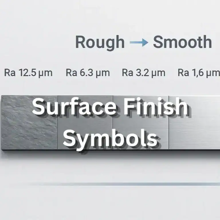
Surface finishing removes unwanted burrs and local defects without altering critical geometry. Around leading and trailing edges, excessive polishing can change aerodynamic shape. Finishing must also consider coating preparation and prevent blockage or damage to cooling passages.
Dimensional Inspection and Quality Control
Quality control verifies that the manufactured vane meets requirements for geometry, material integrity, and functional interfaces. Critical characteristics often include airfoil profile, platform position, mounting dimensions, wall thickness, and cooling-passage condition.
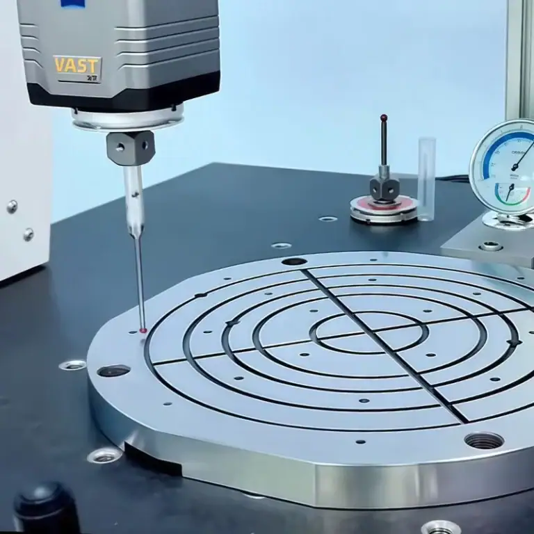
Coordinate measuring machines and optical scanning can inspect accessible surfaces, while computed tomography may be used to evaluate complex internal passages when justified. Dye penetrant inspection, radiography, and other qualified methods can help detect relevant material defects.
A controlled inspection plan also requires material traceability, drawing revision control, and documentation of key manufacturing stages. Acceptance criteria depend on the approved component specification. Accurate machining alone cannot compensate for unacceptable casting defects or incorrect material properties.
| Manufacturing Method | Primary Purpose | Main Limitation |
| Investment Casting | Complex alloy shapes and enclosed channels | Casting defects and dimensional variation |
| 5-Axis CNC Machining | Mounting features and accessible airfoil surfaces | Tool access and cutting forces |
| EDM or Laser Drilling | Small cooling holes and difficult features | Heat-affected surfaces and process control |
| Surface Finishing | Burr removal and surface preparation | Risk of changing critical geometry |
| Quality Inspection | Verify dimensions and material integrity | Access to hidden internal features |
Common Applications of Turbine Vanes
Turbine vanes are used in aircraft engines and industrial gas turbines to direct high-temperature gas through successive turbine stages. Their function remains similar across these applications, but material selection, cooling complexity, operating duration, and manufacturing requirements vary.
Application requirements are established by the complete turbine system. Engineers must consider not only maximum operating temperature but also duty cycle, maintenance interval, fuel conditions, and the consequences of component failure.
Aircraft Gas Turbine Engines
Aircraft gas turbines use stationary vane rows to prepare hot gas for energy extraction by rotating blades. In high-pressure turbine stages, the vanes operate under demanding temperature conditions and often require advanced cooling and protective coatings.
Aerospace components must also meet strict requirements for weight, reliability, traceability, and manufacturing consistency. Design changes can affect engine efficiency, thermal margins, and inspection requirements. These factors make controlled production and documented verification essential.
Precision machining supports functional mounting features and aerodynamic geometry, but aviation components require approved materials, processes, and supplier qualifications. Manufacturing capability must therefore be evaluated alongside the certification and approval requirements of the intended program.
Industrial Gas Turbines and Power Generation
Industrial gas turbines use stationary vanes in systems that drive generators, compressors, and other equipment. These machines may operate for extended periods under demanding thermal and mechanical conditions, making component durability an important consideration.
Industrial applications can involve different fuel compositions, environmental contaminants, and operating schedules. Vanes must resist oxidation, corrosion, thermal fatigue, and local deposits while maintaining suitable aerodynamic performance.
Manufacturing priorities often include repeatable geometry, serviceability, and reliable replacement-part fit. Accurate mounting interfaces and inspection records help reduce assembly problems, while coating and cooling decisions must reflect the specific operating environment.
Common Turbine Vane Problems and Maintenance
Common turbine vane problems include oxidation, hot corrosion, erosion, thermal fatigue, coating damage, and cracking. These conditions may change the airfoil profile, weaken the structure, restrict cooling passages, or reduce turbine performance if they are not identified and managed.
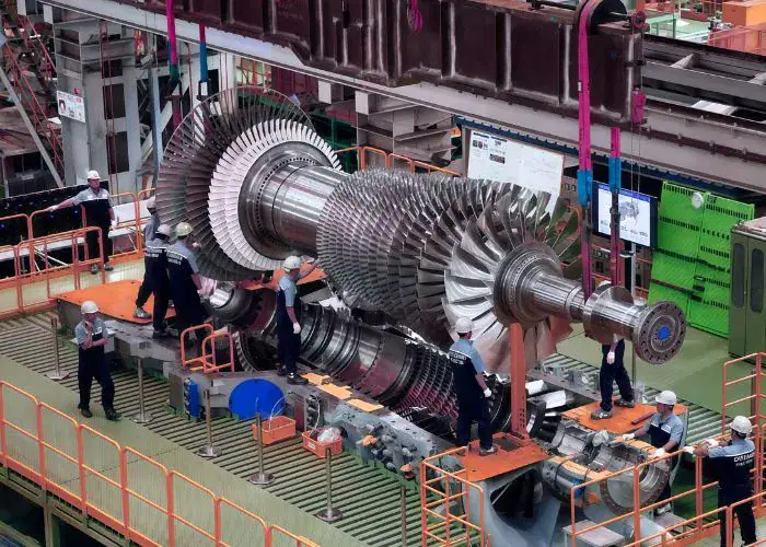
Maintenance must follow the engine manufacturer’s approved procedures and acceptance criteria. The type, location, and severity of damage determine whether cleaning, qualified repair, or replacement is appropriate.
Oxidation, Erosion, and Thermal Fatigue
Oxidation occurs when hot gas reacts with susceptible material surfaces. Hot corrosion can become more severe when contaminants interact with protective surface layers. Erosion from particles or deposits can also change airfoil geometry and increase local aerodynamic losses.
Thermal fatigue develops when repeated heating and cooling cause cyclic mechanical strain. Cracks may form near leading edges, trailing edges, platforms, or cooling holes where temperature gradients and stress concentrations are significant.
Protective coatings and cooling systems help reduce these risks, but they do not eliminate all damage mechanisms. Engineers evaluate temperature history, coating condition, gas contamination, and component geometry to identify the likely causes of deterioration.
Inspection, Cleaning, and Repair Considerations
Inspection methods depend on the damage mechanism and accessibility of the vane. Visual examination can reveal surface erosion, cracks, deposits, or coating loss, while suitable nondestructive methods help investigate less obvious defects.
Cleaning must remove deposits without damaging coatings or changing the airfoil profile. In some approved repair procedures, the blending of blades and vanes in a turbine engine involves carefully removing limited surface damage within specified geometric and material limits.
Repairs involving welding, material removal, or coating restoration require qualified procedures and post-repair inspection. Components with unacceptable cracks, excessive material loss, or compromised cooling features may need replacement rather than further service.
FAQs
What Are Turbine Blades Made Of?
Turbine blades are commonly made from nickel-based superalloys, with selected applications using cobalt-based alloys or ceramic matrix composites. High-pressure rotating blades may use directionally solidified or single-crystal materials to improve high-temperature performance. Stationary turbine vanes may use similar alloys, but their material requirements differ because mechanical loads and mounting conditions are not identical. The final choice depends on gas temperature, creep resistance, fatigue life, oxidation, cooling design, and approved manufacturing specifications rather than one universally suitable alloy.
How Does Vane Geometry Affect CNC Machining Cost?
Vane geometry affects machining cost through surface complexity, cutter accessibility, fixture design, and the number of operations required. Thin trailing edges, deep platform pockets, and difficult mounting angles may require specialized tooling and slower cutting parameters. 5-axis machining can reduce repositioning but also adds programming and simulation work. Engineers should compare total machining time, material removal, and inspection difficulty. For example, simplifying a noncritical mounting feature may reduce setups without changing the aerodynamic airfoil or its performance.
How Are Internal Cooling Passages Inspected Without Cutting the Vane?
Internal cooling passages can be evaluated using industrial computed tomography, qualified radiographic inspection, flow testing, and other methods selected for the component design. Computed tomography can reveal internal geometry and certain defects, although resolution depends on material density, wall thickness, and equipment capability. Flow tests help determine whether the passage network meets specified resistance or flow requirements. Engineers should compare results with approved drawings and acceptance limits because visual access alone cannot establish internal cooling performance.
Why Can Coating Thickness Affect Turbine Vane Assembly?
Coating thickness can affect turbine vane assembly when protective layers are applied near mating surfaces, platform edges, or clearance-sensitive regions. A coating adds material to the original substrate, potentially changing local dimensions and sealing behavior. Engineers must define coating allowances, masking areas, and post-coating inspection requirements before production. For example, a nominal 0.20 mm coating on two opposing surfaces could reduce an opening by approximately 0.40 mm if both surfaces are coated. Actual effects depend on the drawing and coating specification.
When Should A Turbine Vane Be Replaced Instead Of Repaired?
A turbine vane should be replaced when damage exceeds the limits established by the engine manufacturer or approved maintenance documentation. Examples may include unacceptable cracks, excessive material loss, severe distortion, or cooling-passage damage that cannot be restored through qualified repair. Decisions depend on defect depth, location, alloy condition, previous repairs, and remaining service limits. A visually minor defect near a critical stress region may be more serious than larger superficial damage elsewhere. Inspection findings must be evaluated against the approved acceptance criteria.
Conclusion
A turbine vane is a critical stationary component that controls hot-gas flow and supports efficient energy extraction in gas turbine engines. Its performance depends on accurate airfoil design, suitable high-temperature materials, effective cooling, and reliable manufacturing. Investment casting allows complex internal passages to be produced, while precision CNC machining provides accurate mounting surfaces and functional geometry. Understanding these design and manufacturing requirements helps engineers reduce production risks and improve component reliability in demanding applications.
At TiRapid, we provide precision CNC machining and manufacturing services for custom metal components, including multi-axis milling, precision turning, and dimensional inspection. Our manufacturing approach supports complex geometries, accurate mounting features, and consistent quality for demanding engineering applications.