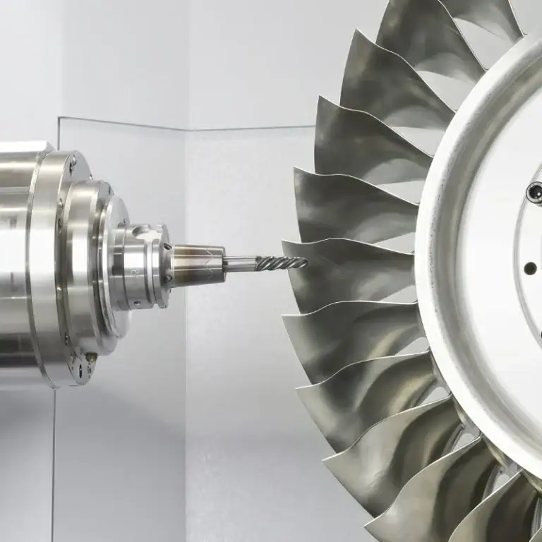
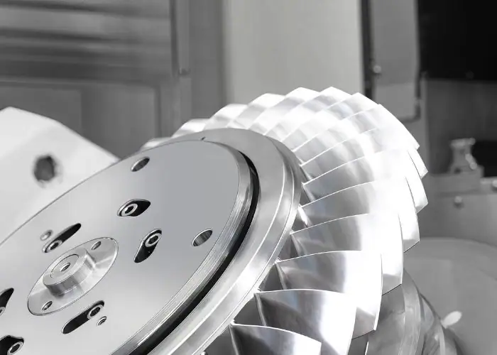
An integrally bladed rotor (IBR), commonly known as a blisk, combines the rotor disk and blades into a single integrated structure. Unlike conventional rotors with separately attached blades, this design eliminates individual blade attachments, reduces component weight, and can improve aerodynamic performance. However, its complex geometry, thin airfoils, and demanding materials make precision manufacturing particularly challenging.
This guide explains how an integrally bladed rotor works, why it is used in aircraft engines, and what engineers must consider during design and manufacturing.
What Is an Integrally Bladed Rotor?
An integrally bladed rotor is a rotating turbomachinery component in which the blades and central disk form one integrated structure. Also called a blisk, it eliminates conventional individual blade attachments and creates a continuous rotor assembly designed for efficient airflow, reduced weight, and reliable high-speed operation.
Traditional bladed disks use separately manufactured blades attached through dovetail roots, disk slots, or other mechanical connections. An integrated design removes these individual joints. The blades may be machined directly from a solid disk or permanently joined to the disk using a qualified manufacturing process.
The term blisk combines the words blade and disk. Integrally bladed rotors are especially common in aircraft engine compressors, where rotating mass, aerodynamic efficiency, and structural reliability are critical. Their design requires coordination between aerodynamic analysis, material properties, rotor dynamics, and manufacturing capability.
A blisk is more than a disk with blades attached to its outer edge. Its blade profiles, disk structure, mass distribution, and mechanical behavior must function as one rotating system. Because individual blades cannot be removed through ordinary mechanical disassembly, manufacturing defects and service damage require particularly careful evaluation.
How Does an Integrally Bladed Rotor Work?
An integrally bladed rotor works by rotating its integrated blades and disk together to transfer mechanical energy between the shaft and the working fluid. In a compressor stage, the rotating blades add energy to incoming air, increasing its total pressure as it moves through the compressor system.
The rotor receives power through the engine shaft. As the blades rotate, their aerodynamic surfaces interact with the flowing air, changing its velocity, pressure, and direction. In a typical axial compressor stage, this process involves four steps:
- Shaft Rotation:The engine shaft drives the integrated disk and blades at the required rotational speed.
- Airflow Entry:Air approaches the rotating blades at an angle determined by upstream flow conditions.
- Energy Transfer:The rotating airfoils transfer mechanical energy to the air, increasing its total pressure.
- Flow Redirection:Downstream stator vanes redirect the airflow for the following compressor stage.
The integrated structure does not change the fundamental compression principle. Its advantage comes from achieving the required aerodynamic function without separate blade-root joints. Engineers must still coordinate rotor geometry with adjacent stators, casing dimensions, and operating clearances to maintain stable compressor performance.
Why Use Integrally Bladed Rotors Instead of Conventional Bladed Disks?
Integrally bladed rotors are used because they can reduce weight, eliminate individual blade attachments, and improve aerodynamic performance in suitable compressor designs. Their continuous structure simplifies certain assembly requirements, although more complex manufacturing and limited blade replacement options must also be considered.
Weight Reduction and Fewer Components
An integrally bladed rotor reduces weight by eliminating blade roots, disk slots, and certain retaining features used in conventional assemblies. These connections require additional material to support each blade. Removing them allows engineers to optimize the disk rim and blade transitions for a lighter rotating structure.
Component count also decreases because individual blades no longer need to be installed and mechanically secured. This can simplify assembly and eliminate certain attachment-related failure mechanisms. The resulting design may support a more compact compressor architecture, depending on the rotor configuration.
Research has reported weight reductions of approximately 20–30% in some blisk designs compared with conventional bladed disks. However, this is not a universal figure. Actual savings depend on blade count, disk geometry, material, engine stage, and the reference assembly used for comparison.
Improved Airflow and Aerodynamic Efficiency
Integrally bladed rotors can improve airflow by removing gaps and geometric interruptions associated with separate blade attachments. Their continuous construction also provides greater freedom to optimize the transition between the airfoil and disk for the required aerodynamic and structural conditions.
Accurate blade positioning and consistent flow passages help maintain the intended airflow distribution. Carefully controlled leading edges, trailing edges, and blade surfaces can limit unnecessary aerodynamic losses. However, compressor efficiency also depends on tip clearances, operating conditions, and surrounding stator geometry.
Higher efficiency should not be assumed simply because a rotor uses integrated construction. Engineers must use computational fluid dynamics, structural analysis, and performance testing to determine whether a proposed blisk offers measurable advantages over a conventional rotor in the intended application.
Maintenance and Repair Limitations
The main maintenance limitation of an integrally bladed rotor is that individual blades cannot be removed and replaced like conventional detachable blades. Damage from foreign-object impact, erosion, fatigue, or contact may therefore require specialized repair procedures or replacement of the complete component.
Repair feasibility depends on the affected location, material, remaining wall thickness, structural loading, and approved service limits. Some local defects can potentially be corrected through controlled blending or qualified material-restoration methods, but not all damage can be repaired safely.
The integrated structure also increases the consequences of certain manufacturing defects. A single unacceptable blade may affect the entire rotor. For this reason, process stability, in-process inspection, and material traceability are essential when evaluating blisk manufacturing quality and total lifecycle cost.
Key Design Features of Integrally Bladed Rotors
The key design features of an integrally bladed rotor include blade geometry, disk structure, material properties, and rotor dynamic behavior. Together, these elements determine aerodynamic efficiency, structural strength, vibration response, and fatigue resistance during high-speed operation.
Blade Geometry and Aerodynamic Performance
Blisk blade geometry includes inlet and outlet angles, chord length, blade height, thickness distribution, and three-dimensional twist. These parameters influence airflow direction, pressure development, and local aerodynamic loading. Their values are determined by the compressor stage and intended operating conditions.
The leading edge must accept incoming airflow while limiting incidence losses. The pressure and suction surfaces then guide the air through the passage, while the trailing edge helps establish the exit flow direction. Blade curvature and thickness also influence local stiffness and structural stress.
Computer-aided design and computational fluid dynamics help engineers evaluate these relationships before production. Manufacturing allowances must be included because profile deviations, excessive tool marks, and inconsistent blade spacing can change the intended flow behavior and reduce aerodynamic performance.
Titanium Alloys and High-Temperature Superalloys
Titanium alloys are commonly used for compressor blisks because they combine relatively low density with high specific strength. Ti-6Al-4V is one familiar engineering example, although the approved grade depends on operating temperature, fatigue requirements, and the engine manufacturer’s specifications.
Nickel-based superalloys may be required for compressor stages operating at higher temperatures. Inconel 718 is an example of an alloy used in demanding aerospace applications. These materials offer useful elevated-temperature strength but generally produce greater cutting resistance and tool wear during machining.
Material selection must consider operating temperature, centrifugal loading, fatigue life, corrosion resistance, and thermal expansion. Machinability is also important because the material affects tool selection, cutting parameters, production time, and surface integrity. A lighter material is not necessarily suitable for every operating condition.
| Material | Main Advantages | Machining Challenges | Typical Use |
| Titanium Alloys | Low density and high specific strength | Heat concentration and tool wear | Selected compressor stages |
| Nickel-Based Superalloys | Elevated-temperature strength and fatigue resistance | High cutting forces and difficult machining | Higher-temperature turbomachinery |
| Stainless Steels | Mechanical strength and selected corrosion resistance | Higher density and possible work hardening | Selected industrial rotor applications |
The final material grade, heat treatment, and certification requirements must follow the approved component specification rather than a general comparison table.
Rotor Dynamics, Vibration, and Fatigue Resistance
Rotor dynamics describes how the integrated disk and blades respond to rotational speed, vibration, and changing mechanical loads. Because the airfoils are directly connected to the disk, the vibration behavior of the blades and supporting structure can interact significantly.
Engineers evaluate natural frequencies, vibration modes, centrifugal stresses, and potential resonance conditions. Finite element analysis and Campbell diagrams help identify interactions between rotor operating speed and vibration frequencies that could threaten structural reliability.
Fatigue resistance depends on material strength, repeated loading, surface condition, and local stress concentrations. Blade-to-disk transitions are especially important because they transfer loads into the central structure. Design validation must consider steady operation, acceleration, deceleration, and relevant transient events.
How Are Integrally Bladed Rotors Manufactured?
Integrally bladed rotors are manufactured using methods such as 5-axis CNC machining, electrochemical machining, grinding, and qualified welding processes. 5-axis machining is particularly important for producing complex airfoil surfaces from solid material, while alternative methods may offer advantages for specialized geometries or production requirements.
5-Axis CNC Machining and Blade Profiling
5-axis CNC machining is a widely used method for producing integrally bladed rotors from solid or forged blanks. Coordinated linear and rotary movements allow cutting tools to access twisted blade surfaces and narrow passages from suitable orientations while controlling the required aerodynamic geometry.
The machining process generally involves three main operations:
Rough Milling: Removes bulk material between blades while retaining sufficient material to support the developing airfoils.
Semi-Finish Milling: Establishes consistent stock allowance and reduces uneven cutting loads before final profiling.
Finish Milling: Produces the specified blade surfaces, leading edges, trailing edges, and blade-root transitions using controlled toolpaths.
Suitable strategies include adaptive roughing, point milling, and flank milling when geometry permits. CAM software must verify tool orientation, holder clearance, and machine limits. During blisk machining, toolpath selection must balance surface finish, machining time, cutting forces, and thin-blade deflection.
Electrochemical Machining for Complex Blade Geometry
Electrochemical machining removes electrically conductive material through controlled anodic dissolution in an electrolyte. Unlike conventional milling, the process does not rely on direct cutting-tool contact, which allows selected complex blisk geometries to be produced without mechanical cutting forces.
ECM can be useful for narrow blade passages and difficult-to-machine alloys where cutting pressure or tool wear limits conventional machining. Pulsed electrochemical machining offers another option for improving local material-removal control in suitable applications.
However, electrochemical machining requires specialized electrodes, electrolyte handling, and accurate control of the machining gap. Material removal depends on electrical and fluid conditions, making process validation essential. Environmental management, dimensional accuracy, and surface integrity must all be considered before choosing ECM.
Grinding and Surface Finishing
Grinding and abrasive finishing processes are used when selected blade surfaces require carefully controlled geometry and surface integrity. They may refine airfoil profiles after rough or semi-finish machining, particularly when conventional cutting methods are limited by difficult materials.
Superabrasive machining can provide an alternative for certain alloys and blade configurations. Its effectiveness depends on tooling accessibility, process stability, material behavior, and the surface requirements defined by the design.
Finishing must preserve leading-edge and trailing-edge geometry because excessive material removal can change blade thickness and aerodynamic behavior. Engineers should establish appropriate finishing allowances and verify that the selected process does not introduce unacceptable surface damage.
Welding and Hybrid Manufacturing Methods
Welding-based manufacturing can form an integrated rotor by permanently joining separately manufactured blades to a disk. Linear friction welding is one established method that creates a solid-state joint using controlled oscillation and pressure.
This approach can offer manufacturing flexibility when producing the blades and disk separately is more practical than machining the complete component from one blank. Other qualified joining or hybrid manufacturing processes may be considered based on material compatibility and component design.
Welded blisks differ structurally from monolithic blisks machined from solid material. Joint integrity, blade positioning, heat effects, and post-weld machining must be verified. Adaptive machining may also be required to compensate for small variations in blade positions after joining.
Comparison of Blisk Manufacturing Methods
Blisk manufacturing methods differ in geometric capability, tooling requirements, production efficiency, and process complexity. 5-axis CNC machining provides flexibility for accessible surfaces, while electrochemical and hybrid methods can address certain limitations of mechanical cutting.
| Method | Main Application | Advantages | Limitations |
| 5-Axis CNC machining | Integrated blade and disk machining | Flexible geometry and precise toolpath control | Tool wear, restricted access, and machining time |
| Electrochemical Machining | Complex conductive-metal passages | Low mechanical cutting force | Specialized electrodes and electrolyte control |
| Grinding | Precision finishing of selected surfaces | Surface refinement and profile control | Accessibility and process-specific surface risks |
| Linear Friction Welding | Permanently joined blade and disk structures | Qualified solid-state joining | Joint inspection and post-weld machining |
| Hybrid Manufacturing | Specialized components and manufacturing routes | Combines complementary process capabilities | Greater process complexity and validation needs |
The best manufacturing method should be selected based on the complete production route rather than one operation. Roughing cost, finishing requirements, material utilization, inspection time, and qualification effort all contribute to the final manufacturing cost.
What Are the Challenges of Blisk CNC Machining?
The main challenges of blisk CNC machining are thin-blade deflection, limited tool access, difficult-to-cut materials, tool wear, and complex programming. These factors can affect blade accuracy, surface quality, machining time, and production reliability if the cutting process is not properly controlled.
Thin Blade Deflection and Limited Tool Access
Thin blisk blades may bend under cutting forces, particularly during finishing when the remaining wall thickness is small. Excessive deflection can create profile errors, uneven surfaces, and vibration. The risk increases with blade height, flexibility, and unsupported length.
Narrow passages also restrict movement of the cutter and tool holder. A tool may reach the intended blade surface but collide with an adjacent airfoil during repositioning. 5-axis motion improves access but cannot eliminate every geometric restriction.
Engineers manage these problems by selecting suitable cutter lengths, controlling cutting engagement, and arranging machining operations to preserve blade support. A stable sequence of roughing and finishing operations is important because removing support material too early can increase deflection.
Tool Wear and Heat Control in Difficult Materials
Titanium alloys and nickel-based superalloys create machining difficulties because of their mechanical and thermal properties. Titanium can concentrate heat near the cutting edge, while nickel alloys may generate high cutting forces and rapid tool wear.
As tools deteriorate, cutting conditions become less consistent. This can produce surface defects, dimensional errors, and changes in the machined surface layer. The problem is particularly important when finishing thin airfoils and critical blade-root transitions.
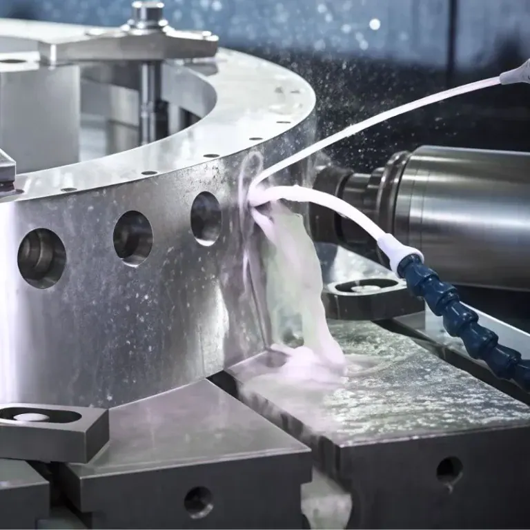
Suitable carbide tools, coatings, coolant delivery, and carefully selected cutting parameters help reduce these risks. Tool condition should also be monitored throughout production. Parameters suitable for aluminum or one titanium alloy should not automatically be applied to another material.
Workholding, CAM Programming, and Toolpath Optimization
Blisk workholding must secure the disk without distorting it or blocking access to critical blade surfaces. Fixtures generally use defined functional datums for positioning, while clamping loads must remain compatible with the disk structure. Poor workholding can create vibration or dimensional errors.
CAM programming must coordinate tool orientation, simultaneous axis movement, entry and exit paths, and collision avoidance. Programming becomes more demanding as blade twist increases and passage width decreases.
Before machining, engineers should verify the following conditions:
- Fixture Clearance:Confirm that clamps and supports do not interfere with tool or rotary-axis movement.
- Tool Accessibility:Check cutter reach, tool-holder clearance, and orientation throughout the blade passages.
- Collision Simulation:Verify movements using models that include the workpiece, fixture, tools, and machine configuration.
- In-Process Verification:Check critical features and machining stability before removing final finishing allowances.
Optimized toolpaths reduce unnecessary repositioning and maintain controlled cutter engagement. These checks are especially valuable when machining costly materials because one collision can damage multiple integrated blades and compromise the entire rotor.
Quality Inspection and Repair of Integrally Bladed Rotors
Quality inspection verifies blade profile accuracy, dimensional relationships, surface condition, and rotor integrity. Repair assessment determines whether local damage can be corrected without compromising mechanical reliability. Both activities are essential because the blades and disk form one rotating component.
Blade Profile Accuracy and Surface Quality Inspection
Blade profile inspection determines whether the manufactured airfoils match the intended aerodynamic geometry. Important features include blade thickness, three-dimensional profile, twist, leading-edge radius, trailing-edge shape, and transitions between the blade and disk.
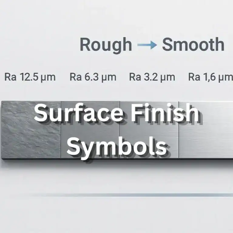
Coordinate measuring machines and optical scanning systems can evaluate complex external surfaces. The selected equipment must provide suitable accessibility and measurement capability for the required tolerance. Surface roughness measurements may also be necessary on specified aerodynamic regions.
Dimensional conformity alone does not establish acceptable surface integrity. A blade can meet its nominal profile but still contain burrs, machining damage, or unacceptable surface defects. Inspection plans must therefore address both geometric accuracy and material condition.
Rotor Balancing and Nondestructive Testing
Rotor balancing evaluates mass distribution to help limit vibration and excessive loads during operation. The acceptable residual unbalance depends on the rotor design, operating speed, assembly configuration, and applicable engineering requirements.
Nondestructive testing helps identify relevant material or manufacturing defects without destroying the component. Depending on the alloy and inspection specification, methods may include fluorescent penetrant inspection, ultrasonic testing, or other qualified techniques.
A properly balanced rotor can still contain cracks, while a structurally sound rotor can have excessive unbalance. Balancing and nondestructive testing therefore address different risks and must be evaluated independently under the approved inspection plan.
Blisk Damage Assessment and Repair Methods
Blisk repair begins with identifying the damage type, location, and severity. Common concerns include foreign-object impact, erosion, fatigue cracking, and local blade deformation. Repair feasibility depends on the affected region, material condition, and approved service limits.
Minor defects may sometimes be corrected through controlled blending or qualified surface-restoration methods. More extensive damage may require specialized material deposition and subsequent precision machining. These methods must not be assumed acceptable for every safety-critical rotating component.
After an approved repair, dimensional inspection, surface evaluation, nondestructive testing, or balancing may be required. The repaired rotor must retain its specified geometry and mechanical integrity. Replacement is necessary when damage exceeds the approved repair or service limits.
Common Applications of Integrally Bladed Rotors
Integrally bladed rotors are primarily used in aircraft engine compressors and selected industrial turbomachinery where low rotating mass, compact construction, and accurate aerodynamic geometry are valuable. The intended application determines material requirements, operating loads, manufacturing methods, and inspection standards.
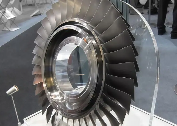
Aircraft Engine Compressors
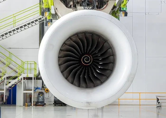
Aircraft engine compressors are among the most important applications of integrally bladed rotors. Blisks eliminate individual blade attachments and can support lighter, more compact compressor designs. These advantages are particularly useful where rotational performance and weight are tightly controlled.
A blisk compressor stage operates together with adjacent stators, casing structures, and other rotor stages. Engineers must match the airfoil geometry to pressure and flow requirements while maintaining acceptable vibration behavior, fatigue life, and running clearances.
For blisk aerospace applications, manufacturing documentation, approved materials, and rigorous inspection are especially important. A machining deviation or structural defect in an engine-critical rotor can have serious consequences, so production requirements must follow the relevant engineering approvals.
Industrial Turbomachinery
Industrial turbomachinery may use integrally bladed rotors in compressors and selected turbine-related systems. The integrated design can be useful where precise flow passages, compact construction, and fewer mechanical interfaces provide an engineering advantage.
Industrial rotor designs can differ substantially from aircraft compressor blisks in operating temperature, duty cycle, and maintenance expectations. The term blisk turbine may refer to certain integrated turbine rotor configurations, but not every turbine wheel or bladed disk is a blisk.
For a custom blisk engine or industrial compressor project, engineers must balance performance, manufacturing cost, and serviceability. Material availability, production volume, geometry, and inspection capability determine whether a monolithic or joined rotor design is the more practical manufacturing solution.
FAQs
Why Are Integrally Bladed Rotors Aerodynamically Better?
Integrally bladed rotors can improve aerodynamic performance because their integrated structure removes certain gaps and geometric interruptions found in conventional blade attachments. Continuous blade-to-disk transitions also provide greater freedom to optimize flow passages. However, aerodynamic performance is not determined by construction alone. Blade angles, surface roughness, tip clearances, and operating conditions still matter. Although some blisk designs have achieved weight reductions of approximately 20–30%, this percentage does not represent aerodynamic efficiency improvement. Actual efficiency gains must be confirmed through analysis and testing.
What Tolerance Should Be Specified for a Blisk’s Airfoil Profile?
Airfoil tolerances should be based on aerodynamic requirements, manufacturing capability, and the inspection method. Critical characteristics include blade profile, thickness, twist, and position relative to the rotor datum system. A project might specify ±0.05 mm for selected dimensional features, but this is an illustrative value rather than a universal blisk tolerance. Engineers should define profile controls and functional datums according to the drawing requirements. Applying unnecessarily tight tolerances to every surface can increase machining and inspection costs without improving performance.
How Much Machining Allowance Should Be Left on a Blisk Blade?
Machining allowance depends on the starting blank, material, blade stiffness, roughing strategy, and finishing requirements. Insufficient stock may leave roughing marks or material variation, while excessive stock can increase cutting forces and finishing time. A preliminary process plan might reserve 0.2–0.5 mm for later machining stages, but this range is only illustrative and must be validated for the actual geometry. Engineers should consider semi-finishing, residual stress, fixture stability, and intermediate measurement results before confirming the final stock allowance.
How Does Blade Count Affect Blisk Machining Cost?
Blade count affects machining cost because additional blades increase the number of aerodynamic surfaces, passages, and features requiring toolpath control. More blades can extend finishing time, reduce tool accessibility, and complicate inspection. However, machining cost does not increase in a simple linear relationship with blade count. Material, blade height, passage width, surface requirements, and machine capability are equally important. A rotor with fewer but deeper, more twisted passages may be harder to machine than one with many short, accessible blades.
Conclusion
An integrally bladed rotor combines the disk and blades into a compact structure that can reduce weight, eliminate mechanical blade attachments, and support efficient aerodynamic performance. However, its complex geometry, demanding materials, and limited repair flexibility create significant manufacturing challenges. 5-axis CNC machining, electrochemical machining, grinding, and qualified joining methods offer different production routes. Choosing the right process requires careful consideration of blade design, material behavior, machining accessibility, surface integrity, and inspection requirements.
At TiRapid, we provide precision CNC machining and manufacturing services for custom metal components, including multi-axis milling, CNC turning, and dimensional inspection. Our manufacturing approach supports complex blade-like geometries, precision mounting features, and reliable custom parts for demanding industrial applications.