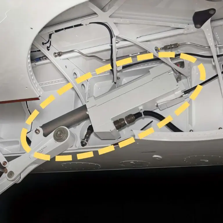
An aerospace actuator is a device that converts electrical, hydraulic, or pneumatic power into controlled mechanical motion. It allows aircraft systems to move flight control surfaces, operate landing gear, open doors, and adjust engine components. Although actuators vary in design and size, they all require reliable movement, precise positioning, and components capable of handling demanding operating conditions.
This guide explains how aerospace actuators work, their different types, and their roles in aircraft systems. It also covers key components, material selection, CNC machining methods, precision requirements, quality inspection.
What Is an Aerospace Actuator?
An aerospace actuator is a mechanical or electromechanical device that converts an energy source into controlled linear or rotary motion. It enables aircraft components to move, hold a position, or respond to commands from pilots and electronic control systems.
Actuators perform many functions that would otherwise require direct mechanical effort. For example, a pilot’s command can cause an actuator to move an aircraft control surface, while another actuator may operate a landing gear mechanism or position a valve in an engine system.
Modern aerospace actuators work with control electronics, sensors, mechanical linkages, and power supplies. Their design depends on the forces involved, required movement, available installation space, operating speed, and safety requirements. A small valve actuator and a major flight-control actuator may therefore have very different constructions.
Reliable actuation also depends on precision-manufactured components. Housings, rods, shafts, mounting brackets, and bearing interfaces must maintain their specified dimensions under load. A small error in alignment or component geometry can affect movement, increase friction, or create assembly problems.
How Do Aerospace Actuators Work?
Aerospace actuators work by converting hydraulic pressure, compressed air, or electrical energy into mechanical movement. A control system determines the required action, and the actuator produces the force and displacement needed to move an aircraft component.
The working principle varies by actuator type, but each system must connect the available energy source with a controlled mechanical output. Position, force, and speed must be appropriate for the intended application.
Converting Energy Into Mechanical Motion
An aerospace actuator converts input energy into movement through a hydraulic piston, pneumatic cylinder, electric motor, or electromagnetic mechanism. The energy source determines how the actuator generates force, while the internal structure determines the direction and range of motion.
In a hydraulic system, pressurized fluid acts on a piston to produce movement. An electromechanical actuator instead uses an electric motor, often combined with gears and a screw mechanism. Pneumatic systems use compressed air, while solenoids create short mechanical movements through electromagnetic force.
The basic operating sequence can be understood in four steps:
Command Input: A pilot or electronic controller requests a specific movement.
Power Delivery: Electrical, hydraulic, or pneumatic power is supplied to the actuator.
Mechanical Movement: The actuator produces linear displacement or rotary motion.
System Response: The connected mechanism moves, and feedback may confirm the resulting position.
The control architecture determines whether the actuator stops at a target position, maintains a specified force, or follows a continuous movement command.
Controlling Position, Force, and Speed
An aerospace actuator controls movement through the relationship between its power source, mechanical transmission, and feedback system. Position control determines where the output moves, force control determines the load it can apply, and speed control determines how quickly the movement occurs.
For example, an electromechanical actuator may use a motor encoder to monitor rotation and a screw mechanism to produce linear travel. A hydraulic actuator may use position sensors and servo valves to control fluid flow and piston movement.
Engineering requirements must account for all three performance characteristics. A high-force actuator may not provide the required positioning accuracy, while a fast actuator may create excessive acceleration or mechanical loading. The final design must balance response time, precision, stability, and operating reliability.
What Are the Different Types of Aerospace Actuators?
The main types of aerospace actuators are hydraulic, pneumatic, electromechanical, and solenoid actuators. They can also be classified by output motion as linear or rotary actuators. Each type offers different advantages in force capacity, response, control accuracy, weight, and system complexity.
Hydraulic Actuators
Hydraulic actuators use pressurized fluid to generate mechanical force. The fluid moves a piston inside a cylinder or drives a hydraulic motor, depending on the required output. Their high force density makes them useful for applications involving substantial mechanical loads.
Aircraft hydraulic actuators are commonly associated with flight-control mechanisms, landing gear, braking systems, and other high-load functions. Their precise control depends on suitable valves, seals, fluid pressure, and properly manufactured internal components.
Hydraulic systems also require careful attention to leakage, contamination, and maintenance. Cylinder bore quality, piston alignment, and sealing surfaces directly influence performance. For engineers evaluating hydraulic actuation, these manufacturing details can be as important as the actuator’s rated force.
Pneumatic Actuators
Pneumatic actuators use compressed air or another suitable gas to create mechanical movement. They generally offer comparatively simple construction and can respond quickly in applications where the available force and control requirements are appropriate.
In aircraft, pneumatic actuation may be used for selected valves, auxiliary mechanisms, and specialized equipment. The exact application depends on the aircraft architecture and available compressed-gas supply. Pneumatic systems should not be treated as universal replacements for hydraulic flight-control systems.
Because gases are compressible, pneumatic systems behave differently from hydraulic systems when loads change. This can make very precise position control more challenging. Engineers must consider pressure variation, leakage, seal compatibility, and the forces required throughout the operating stroke.
Electromechanical Actuators
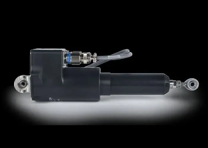
Electromechanical actuators convert electrical power into motion using a motor and mechanical transmission. A typical system may combine a motor, reduction gears, ball screw or roller screw, bearings, and position sensors to achieve controlled movement.
These systems are attractive where precise motion, compact packaging, and integration with electronic controls are important. They can reduce dependence on centralized hydraulic infrastructure in suitable aircraft designs, although load capacity and thermal management remain important considerations.
Electromechanical designs also introduce mechanical transmission challenges. Gear backlash, screw wear, bearing alignment, and motor heat can influence performance. Precision CNC machining is important for the shafts, housings, bearing seats, and mounting features that keep these components correctly aligned.
Solenoid Actuators
Solenoid actuators use an electromagnetic field to create mechanical movement. When electrical current passes through a coil, the resulting magnetic force moves a plunger or armature, allowing the actuator to open, close, or reposition a small mechanism.
These devices are commonly used for switching and control functions such as operating valves, releasing latches, or changing the state of a mechanism. Their relatively short stroke makes them suitable for applications that require rapid, repeatable engagement rather than long-distance travel.
Solenoid performance depends on coil design, magnetic materials, spring forces, and mechanical clearances. A poorly aligned plunger can create friction or inconsistent response. Machined guide surfaces and precise component positioning therefore contribute to reliable operation.
Linear vs. Rotary Actuators
Linear actuators produce movement along a straight path, while rotary actuators generate angular motion around an axis. Both motion types can be produced by different energy sources, including hydraulic and electric systems.
Linear actuator aerospace applications include moving linkages, extending mechanisms, and positioning components that require a push-or-pull action. Rotary designs are used where a mechanism must turn, pivot, or control angular position.
| Actuator Type | Energy Source | Main Advantages | Common Aerospace Functions |
| Hydraulic | Pressurized liquid | High force density | Flight controls, landing gear |
| Pneumatic | Compressed gas | Relatively simple, rapid movement | Selected valves and auxiliary functions |
| Electromechanical | Electric motor | Precise control and electrical integration | Flight controls, doors, positioning systems |
| Solenoid | Electromagnetic force | Fast switching and compact mechanisms | Valves, latches, control functions |
| Linear | Varies | Direct push-and-pull movement | Extension, retraction, linkage control |
| Rotary | Varies | Controlled angular movement | Pivoting and rotational positioning |
The final selection depends on force, travel, speed, available power, environmental conditions, and the aircraft’s approved system architecture.
What Are the Main Applications of Aerospace Actuators?
Aerospace actuators are used in flight control systems, landing gear, aircraft doors, engine mechanisms, and auxiliary equipment. Their main purpose is to convert control commands into reliable mechanical movement that supports aircraft operation, stability, and safety.
Flight Control Systems
Flight control actuators move aircraft surfaces such as ailerons, elevators, rudders, spoilers, and selected high-lift devices. These movements change the aerodynamic forces acting on an aircraft, allowing it to maneuver, maintain stability, and respond to flight commands.
Modern aircraft actuation systems may use hydraulic, electrohydraulic, or electromechanical technology depending on the aircraft design. In fly-by-wire architectures, computers process pilot commands and sensor information before controlling the appropriate actuator.
Accuracy and reliability are essential because incorrect movement can affect aircraft handling. Actuator systems must therefore meet the required response, load, redundancy, and monitoring conditions. These system-level requirements also influence the quality expectations for individual machined components.
Landing Gear and Aircraft Doors
Landing gear actuators extend, retract, or support the movement of aircraft landing gear mechanisms. They must operate under substantial mechanical loads and coordinate with linkages, locking arrangements, sensors, and other supporting components.
Aircraft door actuators may operate passenger doors, cargo doors, access panels, or specialized mechanisms. Their required force, travel, speed, and locking behavior depend on the door design and safety requirements.
These applications often involve precisely machined mounting interfaces, rods, pivot pins, and structural connectors. Poor alignment or excessive clearance can increase wear and create inconsistent motion. Manufacturers must evaluate component geometry and assembly fit alongside the overall actuator specification.
Engine and Auxiliary Systems
Aerospace actuators also support engine and auxiliary functions that require controlled mechanical positioning. Examples may include engine-related valves, variable-geometry mechanisms, thrust-reverser equipment, and selected airflow-control systems.
These applications can operate under demanding temperature, vibration, and environmental conditions. Some actuators must move rapidly, while others must maintain a position against substantial mechanical forces. The appropriate technology depends on the engine or aircraft subsystem.
In auxiliary equipment, actuators may operate cooling-system valves, environmental controls, or other mechanical interfaces. Engineers must consider operating loads, materials, protection against contamination, and the compatibility of actuator components with their surrounding equipment.
Key Components and Design Requirements of Aerospace Actuators
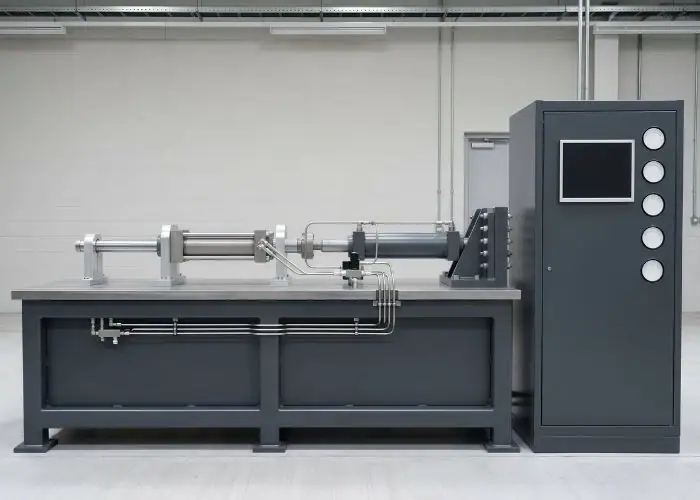
The key components of aerospace actuators include housings, shafts, pistons, rods, bearings, mounting parts, and control-related mechanisms. Their design must balance strength, weight, dimensional accuracy, durability, and reliable movement under the aircraft’s operating conditions.
Housings, Shafts, Rods, and Mounting Components
Actuator housings protect internal components and provide mounting locations for bearings, seals, motors, or hydraulic passages. Their geometry must maintain the alignment of internal mechanisms while resisting external loads and environmental exposure.
Shafts and rods transmit motion or mechanical force between the actuator and its connected equipment. These components often require controlled diameters, straightness, surface quality, and suitable transition radii to reduce friction and avoid excessive stress concentrations.
Mounting components such as clevises, brackets, pins, and bearing supports determine how the actuator connects to an aircraft mechanism. Correct hole positioning, bore alignment, and contact geometry are critical. Even a small positional error can create binding, uneven loading, or premature bearing wear.
Material Selection, Weight, and Durability
Aerospace actuator materials are selected according to mechanical load, operating temperature, corrosion exposure, weight limits, and wear requirements. Aluminum alloys are useful where low weight is important, while steels and titanium alloys may be preferred for selected highly loaded components.
The appropriate material depends on the component rather than the actuator category alone. A lightweight aluminum housing may be suitable for one design, while a highly stressed rod or pin may require steel or titanium. Heat treatment and surface processing can also influence final performance.
Material choice affects machining as well as service life. Aluminum generally permits efficient milling, while high-strength steels and titanium can require more demanding cutting strategies. Engineers must consider material availability, certification requirements, surface integrity, and the total manufacturing process.
| Component | Common Material Options | Important Design Requirements |
| Housing | Aluminum alloys, selected steels | Weight, strength, internal alignment |
| Piston or Rod | Stainless or high-strength steels | Straightness, wear resistance, surface quality |
| Shaft | Alloy steels, stainless steels, titanium alloys | Torsional strength, fatigue resistance |
| Mounting Bracket | Aluminum or titanium alloys | Load capacity, hole positioning, weight |
| Pivot Pin | Hardened or high-strength steels | Wear resistance, dimensional stability |
| Bearing Interface | Qualified metal and bearing materials | Fit, alignment, friction, service life |
Specific material grades must follow the engineering drawing and approved component requirements.
Clutch, Brake, and Position Feedback Integration
Some electromechanical aerospace actuators incorporate clutches, brakes, and position feedback devices. These components help manage movement, hold a load, or provide information to the control system.
A brake may prevent unintended movement when power is removed, while a clutch can connect or disconnect parts of the transmission where required. Position sensors, encoders, or other feedback devices allow the control system to compare commanded motion with actual movement.
Successful integration depends on more than electrical control. Bearing alignment, shaft fits, gear positioning, and sensor mounting geometry must remain stable during operation. Manufacturing errors in these interfaces can increase backlash or produce inconsistent movement even when the electronic control system functions correctly.
How Are Aerospace Actuator Components CNC Machined?
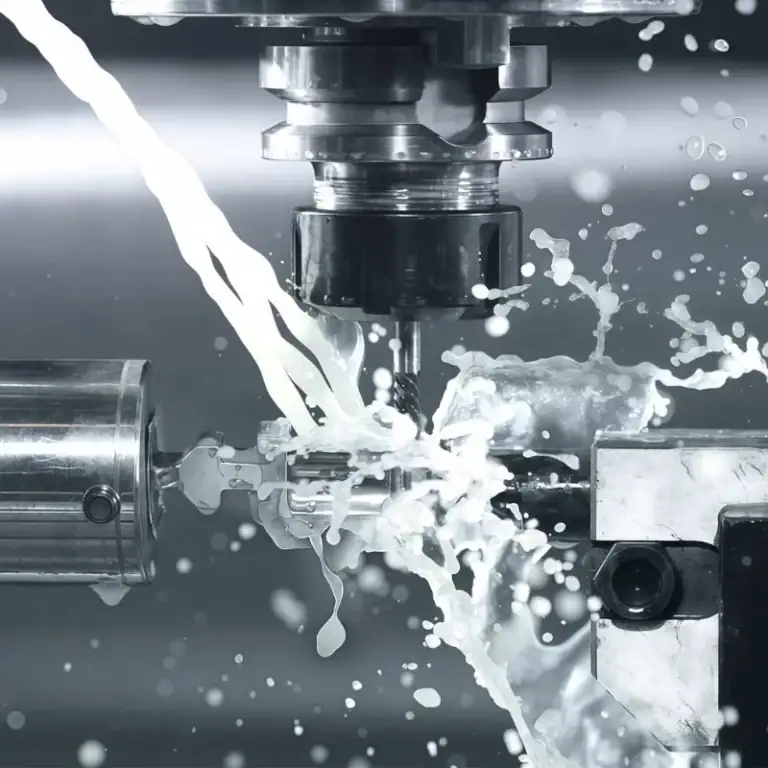
Aerospace actuator components are CNC machined using milling, turning, drilling, boring, threading, and precision finishing operations. These processes create the housings, rods, shafts, and mechanical interfaces needed for controlled movement and reliable assembly.
CNC Milling of Housings and Mounting Features
CNC milling produces actuator housings, mounting brackets, and complex structural components. Three-axis machining is suitable for many accessible features, while four-axis and five-axis methods can improve access to angled surfaces, multiple mounting faces, and complicated geometries.
Housing machining may involve pockets, bearing locations, threaded holes, and mounting surfaces. The machining sequence must preserve consistent datums so that internal features remain correctly positioned relative to external assembly interfaces.
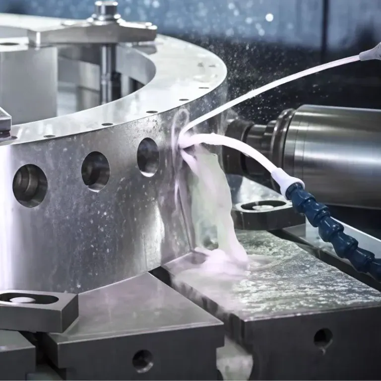
Engineers must also control clamping forces and residual distortion, especially when removing large amounts of material from aluminum components. Appropriate toolpaths, stable fixtures, and intermediate inspection help maintain dimensional accuracy throughout roughing and finishing.
CNC Turning of Shafts, Pistons, and Rods
CNC turning is used to machine cylindrical actuator components such as shafts, pistons, sleeves, and rods. The process produces specified diameters, shoulders, grooves, and threaded features while maintaining relationships between rotational surfaces.
For a precision shaft, the important characteristics may include diameter accuracy, concentricity, surface finish, and straightness. A part that meets one diameter requirement can still cause assembly problems if its bearing surfaces are misaligned.
Production planning should consider the component’s length-to-diameter ratio, material, and required finishing process. Long or slender rods may need additional support during machining, while tightly controlled bearing or seal interfaces may require qualified grinding or honing operations after turning.
5-Axis CNC Machining of Complex Actuator Components
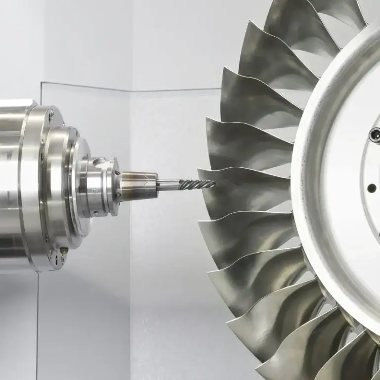
5-axis CNC machining is particularly useful for aerospace actuator parts with angled mounting surfaces, complex contours, and features located on multiple sides. By adjusting the cutting tool orientation, it improves access to difficult areas and reduces repeated setups, helping maintain consistent relationships between critical features.
For complex actuator housings and brackets, 5-axis machining can improve the accuracy of angled holes, mounting interfaces, and intersecting surfaces. However, successful machining still requires stable fixtures, suitable tool lengths, and carefully programmed toolpaths. CAM simulation helps prevent collisions and unnecessary tool movements.
Engineers must also consider material behavior, cutting forces, and inspection requirements. Thin-walled aluminum housings may deform if clamping pressure or material removal is poorly controlled. A well-planned 5-axis process helps improve machining stability, reduce positioning errors, and maintain the dimensional accuracy needed for reliable assembly.
Precision Machining of Bores, Threads, and Mating Surfaces
Precision machining of actuator bores, threads, and mating surfaces is essential because these features determine assembly fit, movement alignment, and sealing behavior. Critical dimensions are selected according to the functional requirements of the actuator rather than a universal tolerance applied to every part.
Bores and bearing seats may require careful control of diameter, roundness, cylindricity, and position. Threaded connections must match the specified thread form and engagement length. Mating surfaces may need appropriate flatness, perpendicularity, or surface texture.
Key machining controls include:
- Datum Consistency:Maintain stable references between related features.
- Bore Alignment:Verify coaxiality and positional relationships of bearing and guide surfaces.
- Surface Integrity:Control burrs, tool marks, and machining-induced damage.
- Thread Verification:Check specified thread forms and assembly compatibility.
- Thermal Stability:Allow precision parts to reach suitable measurement conditions before critical inspection.
The required limits must come from the engineering drawing and approved manufacturing plan. Tight tolerances add cost and should be applied where they contribute to mechanical performance.
Quality Control and Reliability of Aerospace Actuator Components
Quality control for aerospace actuator components focuses on dimensional accuracy, material condition, surface quality, process traceability, and compliance with approved manufacturing requirements. These controls help ensure that machined parts fit correctly and maintain reliable mechanical performance.
Dimensional Inspection and Surface Quality
Dimensional inspection confirms that actuator parts meet drawing requirements for size, position, form, and orientation. Coordinate measuring machines, precision gauges, and other suitable instruments can be used to verify housing bores, mounting interfaces, shaft diameters, and critical alignment features.
Surface quality is important for sliding, sealing, and bearing-contact areas. Excessive roughness, scratches, or machining marks may increase friction or affect seal performance. The inspection method must match the specified surface characteristics and functional requirements.
Engineers should also consider measurement uncertainty and temperature stability. Parts with tight tolerances may require controlled measurement conditions to avoid thermal expansion affecting inspection results. Dimensional conformity must be assessed together with burr control, cleanliness, and material integrity.
Material Traceability and Manufacturing Quality Requirements
Material traceability connects a finished component to its approved material identification, production records, and applicable technical requirements. For aerospace projects, this may involve heat or lot records, processing history, inspection reports, and controlled drawing revisions.
Quality management requirements depend on the customer contract and application. ISO 9001 provides a general quality management framework, while AS9100 adds aerospace-specific requirements. Some programs also require first article inspection, approved special processes, and additional supplier controls.
When reviewing aerospace actuator manufacturers and aerospace actuators suppliers, buyers should distinguish complete-system manufacturers from precision component subcontractors. Electromechanical actuators suppliers may provide approved assemblies, while a CNC machining provider typically manufactures specified housings, shafts, brackets, and other parts to customer drawings.
Supplier approval must therefore be checked for the exact project. A manufacturer’s general machining capability does not automatically establish eligibility to manufacture flight-critical components or perform regulated aircraft maintenance.
Maintenance, Repair, and Replacement Considerations
Aerospace actuator maintenance focuses on identifying conditions that could affect movement, load transfer, or system reliability. Common concerns include hydraulic leakage, worn seals, excessive mechanical clearance, contamination, abnormal vibration, and degraded actuator response.
Repair or replacement decisions must follow the approved maintenance documentation. A worn shaft or housing cannot automatically be remachined and returned to aircraft service simply because its original dimensions are known. Material condition, repair limits, and authorization must be evaluated.
For components that can be repaired under approved procedures, machining may be one part of a larger restoration process. The complete repair may also require special processing, inspection, assembly, functional testing, and documented release. These activities must be performed by appropriately authorized organizations.
Future Trends in Aerospace Actuation Systems
Future aerospace actuation systems are moving toward more electrical control, higher power density, reduced weight, and improved monitoring capability. Hydraulic technology will remain important, while electromechanical and electrohydrostatic solutions will expand where they offer suitable system-level benefits.
The Shift Toward Electromechanical Actuation
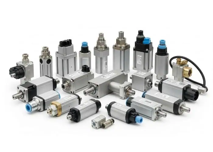
Electromechanical actuation is becoming more attractive because electric motors and electronic controllers can provide controlled movement without requiring every function to use a centralized hydraulic supply. This supports the broader development of more-electric aircraft architectures.
However, the transition is not a complete replacement of hydraulic systems. High-force applications still benefit from established hydraulic technology, while electrical systems introduce challenges involving thermal management, power electronics, and mechanical transmission reliability.
Industry development is therefore focused on selecting the most suitable solution for each function. Electromechanical, electrohydraulic, and electrohydrostatic systems may operate alongside conventional hydraulics. Their different architectures create demand for specialized housings, transmission components, and accurately machined interfaces.
Lightweight, Compact, and High-Reliability Designs
Lightweight actuator design aims to reduce aircraft mass without sacrificing force capability or fatigue performance. Engineers may use compact transmissions, optimized housings, integrated sensing, and higher-performance materials to reduce the size and weight of complete systems.
Smaller packaging creates new manufacturing challenges. Thin housing walls, closely spaced mounting features, and reduced assembly clearances can increase the difficulty of CNC machining and dimensional inspection. Component geometry must remain practical to manufacture and maintain.
High reliability also requires attention to load paths, wear, thermal effects, and repeated operating cycles. Aerospace actuator components must continue to meet their specified performance requirements throughout the intended service life. Precision machining supports this objective by improving the consistency of critical mechanical interfaces.
FAQs
How Are Actuators Used In Aerospace?
Aerospace actuators convert commands into mechanical movement for flight controls, landing gear, doors, engine mechanisms, and auxiliary systems. Hydraulic units are useful for high-force applications, while electromechanical designs provide precise electronically controlled motion. Some aircraft also use pneumatic or solenoid actuators for specialized functions. An actuator may move a surface, operate a latch, or position a valve. The correct technology depends on required force, movement, response time, available power, and the aircraft’s approved control architecture.
How Much Do Aerospace Actuators Cost On A Plane?
Aerospace actuator prices vary significantly by aircraft model, function, certification status, and whether the unit is new or used. For example, a publicly listed Cirrus SF50 nose landing gear hydraulic actuator was priced at approximately $17,857, while an FAA estimate for replacing a particular Airbus A320-family stabilizer actuator listed around $240,000 in required parts per aircraft. These are different components and purchasing circumstances, not a standard market price. Installation, inspection, and maintenance costs may be additional.
How Can Backlash Affect Aerospace Actuator Accuracy?
Backlash is the small amount of lost motion that occurs when mechanical transmission components reverse direction. In an electromechanical actuator, it may originate from gears, screw-and-nut assemblies, or worn joints. For example, a 0.10 mm reversal gap can create a positioning error if the controller does not account for it. Engineers reduce this risk through suitable transmission design, bearing preload, controlled machining fits, and feedback strategies. The acceptable backlash must be determined from the actuator’s functional accuracy requirements.
Can Aluminum And Steel Actuator Parts Cause Galvanic Corrosion?
Yes. Aluminum and steel components can experience galvanic corrosion when they are electrically connected and exposed to a suitable electrolyte, such as moisture containing salts. The risk depends on alloy selection, surface condition, environmental exposure, and protective measures. Engineers may use compatible coatings, insulating barriers, sealants, or controlled drainage to reduce the problem. For example, a precision-machined aluminum housing with steel fasteners needs appropriate corrosion protection in a demanding environment. Coating thickness and final assembly dimensions must also be considered.
Conclusion
An aerospace actuator converts electrical, hydraulic, or pneumatic energy into controlled mechanical motion for aircraft systems. Its reliability depends on suitable actuation technology, effective component design, appropriate material selection, and accurate manufacturing. CNC milling, turning, and precision finishing are important for producing housings, shafts, rods, and critical mechanical interfaces. Engineers must also evaluate operating loads, alignment, surface integrity, quality documentation, and long-term maintenance requirements before selecting a manufacturing approach.
At TiRapid, we provide precision CNC machining and manufacturing services for custom metal components, including aluminum housings, stainless steel shafts, mounting brackets, and complex precision features. Our CNC milling, turning, multi-axis machining, DFM support, and dimensional inspection help customers manufacture accurate, reliable parts for demanding engineering applications.