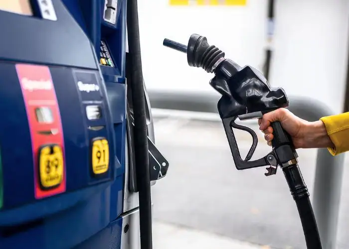
A gas pump nozzle is a fuel dispensing component that controls fuel delivery from a station’s dispenser into a vehicle’s tank. It combines a mechanical valve, handle, spout, and, in automatic models, a shutoff mechanism to help prevent overfilling. Although it looks simple, its performance depends on precise internal components, fuel-compatible materials, and reliable sealing surfaces.
This guide explains how a gas pump nozzle works, including fuel flow, automatic shutoff, and vapor recovery. It also covers the main components, nozzle types, material selection, safety features, CNC machining, selection requirements, and maintenance.
What Is a Gas Pump Nozzle?
A gas pump nozzle is a handheld fuel dispensing device that controls the flow of gasoline or diesel from a fuel dispenser into a vehicle’s tank. It connects to a fuel hose and uses an internal valve to start, regulate, and stop fuel delivery. Automatic models also include a mechanism that responds when fuel reaches a sensing opening near the spout.
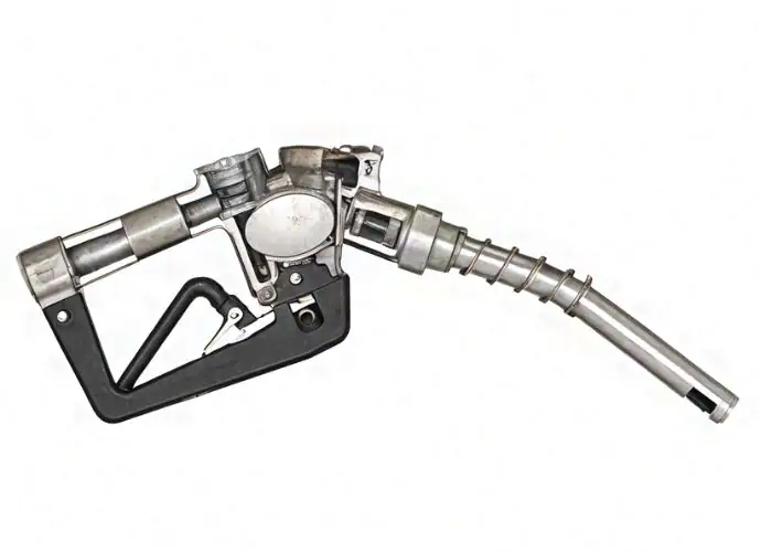
The term gas pump nozzle usually refers to the complete handheld assembly, not just the metal tube inserted into the vehicle. It includes the nozzle body, operating lever, valve mechanism, spout, sealing components, and fuel inlet connection. These parts must work together to control liquid fuel under specified operating conditions.
The nozzle itself does not normally generate the pressure needed to move fuel. That pressure comes from the station’s pumping system. The nozzle acts as the final mechanical flow-control device between the dispenser and the vehicle. Its internal passages and valve design influence pressure loss, handling effort, and shutoff performance.
Modern fuel nozzle designs emphasize reliable sealing, controlled flow, and compatibility with the intended fuel. For equipment manufacturers, this means even relatively small components, such as valve seats, threaded connectors, and sensing passages, can have a significant effect on overall product performance.
How Does a Gas Pump Nozzle Work?
A gas pump nozzle works by opening an internal valve when the operator squeezes the handle, allowing pressurized fuel to pass through the nozzle and into the vehicle. In an automatic fuel nozzle, a Venturi-based sensing mechanism releases the handle mechanism when liquid covers the sensing port, stopping the flow.
Fuel Flow and Valve Control
Fuel flows through a gas pump nozzle when pressure from the dispensing system pushes it through the inlet, internal valve, and discharge spout. Squeezing the handle moves a mechanical linkage that opens the valve against its closing force, allowing fuel to enter the vehicle’s tank.
The amount of fuel delivered depends on dispenser pressure, valve opening, passage geometry, and downstream resistance. Some nozzle mechanisms allow the operator to adjust flow by changing handle position. The dispenser’s metering system, rather than the nozzle alone, measures the quantity sold.
When the handle is released, a spring-loaded valve returns toward its closed position and stops the flow. Accurate valve alignment, smooth movement, and suitable sealing materials help reduce leakage and inconsistent operation. Excessive internal restriction can also increase pressure loss and reduce the achievable flow rate.
How Automatic Shutoff Works Using the Venturi Effect
An automatic fuel nozzle typically uses a small sensing opening near the end of the spout, an internal air passage, and a diaphragm-operated release mechanism. Fuel passing through a Venturi section generates suction while the sensing opening remains exposed to air.
When rising fuel or splashback covers the sensing opening, air can no longer enter freely. The resulting increase in vacuum acts on a diaphragm and releases the handle’s holding mechanism. A spring then closes the main valve, stopping fuel delivery without requiring the operator to release the handle manually.
The mechanism responds to the sensing opening being blocked, not to a direct electronic measurement of tank capacity. That distinction matters because splashback, foaming, poor spout positioning, or a restricted sensing passage can cause the nozzle to shut off before the tank is full.
How Vapor Recovery Systems Work
A vapor recovery nozzle helps capture gasoline vapors displaced from a vehicle’s tank during refueling. In station-based Stage II vapor recovery systems, the nozzle and associated equipment provide a separate path for vapors to return through the recovery system rather than escaping freely into the surrounding air.
Depending on the system, vapor collection may use a flexible boot, a separate vapor passage, or vacuum-assisted equipment. The vapor path must remain compatible with the nozzle, hose, dispenser, and storage system. These components are engineered as a connected vapor-control arrangement.
Not every gas pump nozzle includes Stage II vapor recovery. Many vehicles have onboard refueling vapor recovery systems, and station requirements vary by location. Engineers must therefore verify the applicable environmental rules and equipment certification rather than assuming every modern nozzle requires the same vapor-control configuration.
What Are the Main Parts of a Gas Pump Nozzle?
The main parts of a gas pump nozzle are the spout, body, handle, internal valve, automatic shutoff components, seals, springs, and fuel inlet connection. Each part serves a different function, from guiding fuel into the tank to controlling flow, preventing leakage, and supporting reliable mechanical operation.
Nozzle Spout, Handle, and Main Valve
The nozzle spout is the discharge tube inserted into the vehicle’s filler neck. Its outer diameter, length, bend, and outlet geometry must suit the intended application. A properly designed spout also positions the sensing opening and supports predictable fuel delivery.
The handle and operating lever transmit the user’s input to the internal valve. Their geometry influences opening force, operating travel, and ease of handling. Guards and insulating covers may improve protection and usability, depending on the product design.
The main valve controls liquid fuel flow through the nozzle body. Its seat geometry, moving components, and spring force determine how it opens and closes. Precision machining is especially important where valve parts must move smoothly while maintaining a dependable seal.
Sensing Port, Diaphragm, and Shutoff Mechanism
The sensing port is a small opening near the spout tip that connects to the automatic shutoff system. Its location and unobstructed air passage are essential because the mechanism depends on the pressure change created when the opening becomes covered by liquid.
A flexible diaphragm converts the pressure difference into mechanical movement. This movement releases a latch or linkage associated with the handle. The valve’s closing spring then ends fuel delivery, providing a mechanical shutoff function without requiring a separate tank-level sensor.
The sensing system contains small passages and moving parts that require consistent geometry. Poor assembly, contamination, damaged diaphragms, or restricted sensing openings can affect shutoff behavior. These features require careful manufacturing, assembly, and functional verification.
Seals, Springs, and Hose Connections
Seals prevent fuel from escaping around valve stems, joining surfaces, and internal flow passages. Their performance depends on material compatibility, compression, surface finish, and the operating pressure. A seal that works with one fuel formulation may not be suitable for another.
Springs provide closing force and control mechanical return movements. They must maintain their intended characteristics throughout repeated operating cycles. Incorrect spring selection or poor assembly can change opening effort, valve response, and shutoff reliability.
The hose connection provides the mechanical and fluid interface between the nozzle and dispensing equipment. Thread geometry, sealing arrangements, and optional swivel connections must match the system design. Incorrect connections can create leakage, assembly damage, or excessive pressure loss.
What Are the Different Types of Gas Pump Nozzles?
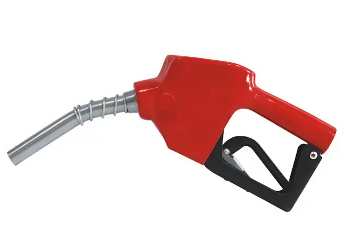
Gas pump nozzles are commonly classified by operating mechanism, fuel type, flow capacity, and vapor-control requirements. The main categories include manual nozzles, automatic shutoff nozzles, gasoline and diesel nozzles, vapor recovery nozzles, and high-flow dispensing models.
Manual vs. Automatic Fuel Nozzles
A manual fuel nozzle relies on the operator to release the handle when the desired amount of fuel has been delivered. It generally has a simpler control arrangement, although some manual designs still include flow-control features for particular industrial applications.
An automatic fuel nozzle adds a mechanical shutoff function that responds to the sensing system. This feature is especially useful for routine vehicle refueling because it helps prevent accidental overfilling when the sensing mechanism operates correctly.
The choice between manual and automatic designs depends on the intended use, applicable rules, and operating environment. Automatic shutoff is not a substitute for supervision. Equipment compatibility and manufacturer instructions remain essential for safe fuel dispensing.
Gasoline vs. Diesel Fuel Nozzles
Gasoline and diesel fuel nozzles may differ in spout size, flow capacity, internal seals, and intended equipment connections. Their construction must match the physical and chemical properties of the fuel and the corresponding dispensing system.
Some diesel nozzles use larger spouts and higher flow capacities for commercial trucks or bulk fueling. However, these characteristics are model-dependent. A nozzle’s color or handle shape cannot reliably establish fuel compatibility across every region or station.
Fuel selection must be based on product identification and approved specifications. This is particularly important when equipment must handle gasoline containing ethanol or diesel containing biodiesel, because the fuel blend can affect elastomer and other material choices.
Vapor Recovery and High-Flow Fuel Nozzles
Vapor recovery nozzles are designed for systems that collect gasoline vapors during filling. They may include additional passages or specialized interfaces that conventional nozzles do not require. The appropriate arrangement depends on the station’s environmental-control equipment.
High-flow nozzles are designed to deliver fuel at greater rates where the pump, hose, receiving tank, and approved operating procedure allow it. Larger internal passages and different valve arrangements may reduce restrictions, but flow capacity must be evaluated for the complete system.
As one product-specific example, a commercial automatic nozzle is advertised with a flow range of up to 60 L/min. Other models use substantially different flow capacities. Engineers should compare manufacturer performance curves and rated conditions instead of treating one flow figure as a universal standard.
What Materials Are Gas Pump Nozzles Made Of?
Gas pump nozzles are commonly made from aluminum alloys, selected steels, fuel-resistant elastomers, and engineering polymers. Metal components provide strength and dimensional stability, while sealing and protective materials are chosen for chemical compatibility, wear resistance, and reliable operation.
Aluminum and Stainless Steel Components
Aluminum is widely used for nozzle bodies because it provides useful strength at relatively low weight. It can be formed into complex housings and subsequently machined to produce accurate valve cavities, sealing features, and threaded connections.
Stainless steel may be used for selected components where mechanical strength, corrosion resistance, or wear performance is important. The appropriate grade depends on the fuel environment and component function. Stainless steel is not automatically required for every fuel-contact surface.
Machining behavior also influences material selection. Aluminum generally allows efficient cutting and good dimensional control, while stainless steel may require greater attention to work hardening, heat generation, and tool wear. The final choice should balance functional needs and manufacturing cost.
Fuel-Resistant Seals and Engineering Plastics
Fuel-resistant elastomers are used in gaskets, valve discs, diaphragms, and other sealing features. Depending on the application, these may include suitably specified fluorocarbon or other qualified compounds. Compatibility must be checked against the actual gasoline, ethanol blend, or diesel formulation.
Engineering polymers may be used for lever guards, handle insulation, bushings, or selected mechanical parts. Their advantages can include low weight, impact resistance, and improved handling comfort. Not every engineering plastic is suitable for continuous contact with liquid fuel.
PTFE-based materials may also be used in selected sealing arrangements. However, material names alone do not guarantee compatibility. Temperature, swelling, permeation, mechanical loading, and long-term exposure must be considered before approving a material for production.
How Material Selection Affects Durability and Safety
Material selection affects durability by determining how nozzle components respond to fuel exposure, repeated movement, temperature changes, and mechanical stress. A poorly matched seal may swell or harden, while an unsuitable metal component may experience premature wear or corrosion.
For example, aluminum can reduce housing weight, but the valve seat must still maintain the required surface quality and dimensional stability. Likewise, a strong polymer may perform well as a protective guard but be unsuitable for a highly loaded sealing interface.
One commercial nozzle specification lists an aluminum body, a polymer lever guard, graphite/PTFE packing, and a fluorocarbon valve disc. This illustrates why multiple material families are often used in a single assembly rather than one material throughout.
| Component | Common Material Options | Main Engineering Requirements |
| Nozzle Body | Aluminum alloys | Strength, low weight, accurate internal passages |
| Spout | Aluminum or suitable metal alloys | Wear resistance, geometry, fuel compatibility |
| Valve Components | Selected metal alloys | Dimensional stability, smooth movement, sealing |
| Gaskets and Seals | Qualified fuel-resistant elastomers | Chemical compatibility, compression, leakage prevention |
| Handle Guards | Engineering polymers | Impact resistance, durability, user protection |
| Packing and Bushings | PTFE-based or qualified polymers | Wear behavior, chemical resistance, suitable friction |
The final material specification must be verified against the intended fuel blend and the nozzle manufacturer’s qualification requirements.
Key Safety Features of Gas Pump Nozzles
The main safety features of gas pump nozzles are automatic shutoff, controlled valve closure, fuel-tight sealing, and, on certain models, vapor recovery or additional interlocks. These features help limit spills, unintended fuel discharge, static-related hazards, and emissions when the equipment is correctly selected and maintained.
Overfill Prevention and Spill Protection
Automatic shutoff helps prevent overfilling by closing the valve when the sensing opening becomes covered by rising fuel or splashback. Its effectiveness depends on proper spout insertion, unobstructed sensing passages, and a correctly functioning mechanical release system.
Some designs add no-pressure/no-flow protection, which prevents fuel discharge unless the dispenser is pressurized. Others may include features that respond when the nozzle is dislodged. These functions are model-specific and should not be assumed present in every automatic nozzle.
Engineers must consider how the complete system behaves during interrupted fueling, accidental handle operation, or loss of dispenser pressure. Functional testing should confirm that the relevant protective mechanisms operate under the conditions specified by the approved design.
Static Electricity and Fuel Leakage Prevention
Static electricity is a concern because fuel movement and refueling activities can create charge differences in the dispensing environment. Approved fueling equipment must provide the required electrical continuity and compatibility with the station’s safety arrangements.
Nozzle bodies, hoses, swivels, and related components must be selected as an appropriate system. Insulating handle covers can improve usability but do not replace electrical bonding or other safety requirements. Metal construction alone does not guarantee safe static-control performance.
Fuel leakage prevention depends on accurate valve seating, suitable seals, and correctly assembled connections. Damaged threads, worn seats, or incompatible elastomers can compromise sealing. Precision machining contributes to the mechanical fit, while complete nozzle safety depends on validated assembly performance.
Safe Pressure Control and Vapor Emissions
Fuel nozzles must operate within the specified pressure range of their dispensing system. Excessive pressure or unsuitable flow characteristics can affect valve operation, connection loads, and shutoff behavior. The nozzle must therefore be selected for the actual system conditions.
Some commercial nozzle designs have a maximum rated working pressure of 50 psi, approximately 3.45 bar. This is a product-specific example, not a universal rating. The dispenser, hose, swivel, and nozzle must each be compatible with the required pressure and flow conditions.
Environmental performance also depends on controlling liquid drips and gasoline vapor emissions. Where vapor recovery is required, approved components must work together as a qualified system. In other installations, conventional or enhanced conventional nozzles may be appropriate under local regulations.
How Are Gas Pump Nozzle Parts Manufactured?
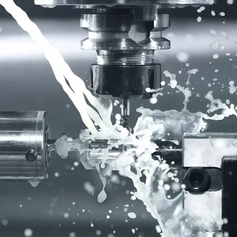
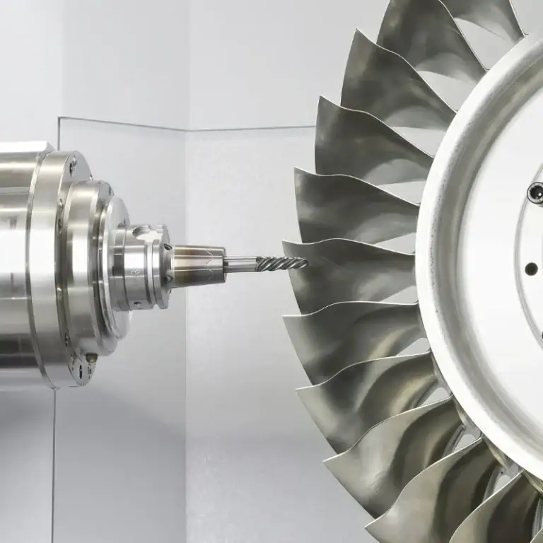
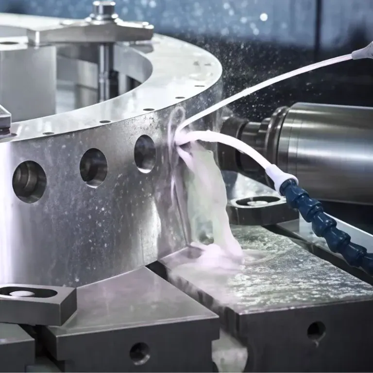
Gas pump nozzle parts are manufactured using casting, CNC machining, molding, forming, and precision assembly, depending on the component. CNC machining is especially valuable for valve cavities, threads, mating surfaces, and other metal features that require controlled dimensions and reliable mechanical fit.
CNC Machining of Nozzle Bodies and Valve Components
Nozzle bodies may be produced from castings or other suitable metal blanks, followed by CNC machining of their functional features. Milling and drilling can create valve openings, connection ports, and internal passages, while turning may be used for cylindrical valve components.
The machining plan must consider wall thickness, tool access, and datum selection. Internal passages should maintain the geometry required for the valve mechanism and fluid flow. Excessive material removal near thin sections can reduce rigidity or create unwanted distortion.
For custom manufacturing, engineers should review whether a feature can be machined from a practical tool direction. A housing that requires excessive setups or very long cutters may benefit from a different blank design, revised parting arrangement, or simplified noncritical features.
Precision Machining of Sealing Surfaces and Threads
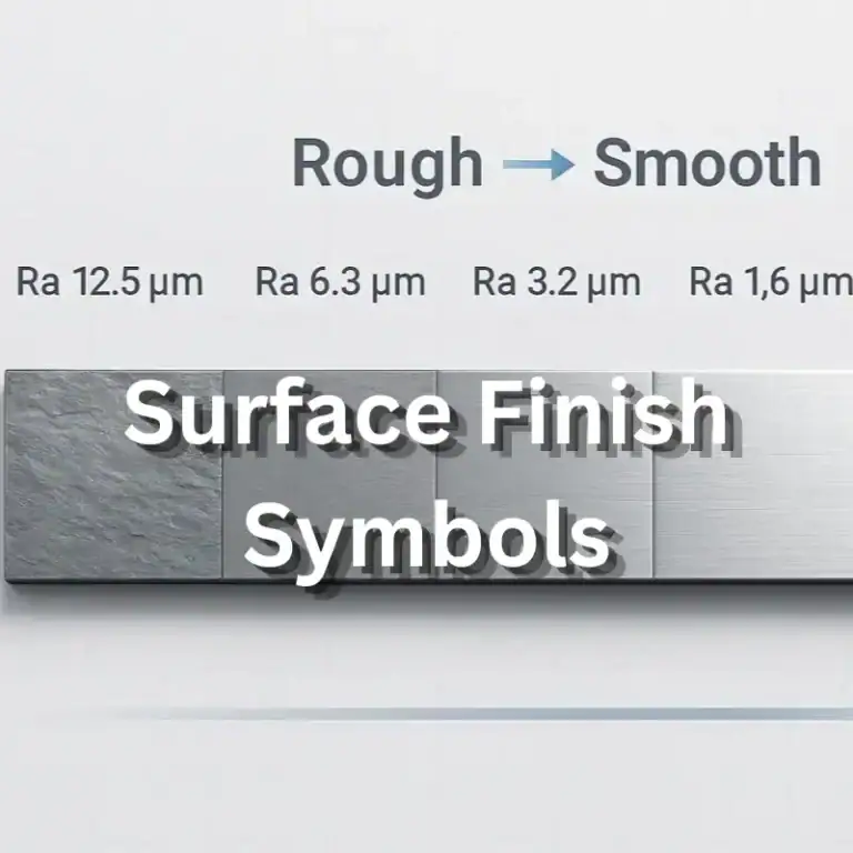
Sealing surfaces require appropriate flatness, roundness, surface texture, and dimensional relationships to support reliable contact. The required values depend on the seal material, valve geometry, and operating pressure rather than one universal nozzle tolerance.
Threaded connections also need controlled geometry to match the intended hose or swivel interface. Engineers must identify whether the design uses tapered or parallel threads and follow the applicable thread specification. Similar nominal sizes do not necessarily mean two connections are interchangeable.
Critical machining considerations include:
- Valve Seat Geometry:Maintain the specified contact profile and surface condition.
- Bore Alignment:Control the relationship between moving valve parts and their guiding surfaces.
- Thread Accuracy:Verify the specified thread form, engagement, and sealing arrangement.
- Burr Control:Remove loose edges and chips that could interfere with valve movement or obstruct small passages.
A feature may meet its nominal dimension but still perform poorly if burrs, surface defects, or positional errors remain. Functional machining quality therefore requires more than measuring isolated dimensions.
Surface Finishing, Assembly, and Quality Testing
Surface finishing prepares machined components for assembly and their intended operating environment. Depending on the design, processes may include deburring, cleaning, compatible protective treatments, and controlled finishing of sealing areas. Coatings must not interfere with critical fits.
During assembly, valve components, springs, diaphragms, and seals must be installed in the correct sequence and orientation. Contamination or damaged sealing features can cause poor movement, leakage, or unreliable automatic shutoff even when individual metal components meet their drawings.
A suitable quality plan may include dimensional inspection, visual checks, leakage testing, flow verification, and automatic-shutoff testing. Tests must follow the product specification and applicable safety requirements. Precision machining supports these outcomes, but certification of a complete nozzle requires separate product-level validation.
How to Choose the Right Gas Pump Nozzle?
The right gas pump nozzle is selected by matching its rated flow, working pressure, fuel compatibility, spout dimensions, and connection type to the dispensing system. Automatic shutoff performance, environmental requirements, and approved equipment specifications must also be considered before installation.
Flow Rate and Working Pressure Requirements
Flow rate determines how much fuel can pass through the nozzle under specified conditions. Higher flow rates may shorten refueling time, but the nozzle must remain compatible with the receiving tank, hose, dispenser, and permitted operating conditions.
Working pressure is equally important because nozzle valve operation and internal pressure loss depend on the pressure available from the system. A model designed for one operating range may not perform correctly when connected to equipment outside its approved limits.
The full pressure-flow relationship should be reviewed using manufacturer data. Maximum flow and maximum pressure are not necessarily achieved together. Engineers should compare the expected operating point with the nozzle’s rated performance instead of selecting solely from headline numbers.
Fuel Compatibility and Nozzle Size
Fuel compatibility must be confirmed for the exact liquid being dispensed. Gasoline, ethanol-gasoline blends, diesel, and biodiesel blends may impose different requirements on valve discs, seals, hoses, and other wetted materials.
Spout size must fit the intended filler neck and relevant equipment interface. Some commercial nozzle families provide different spout diameters for different fueling applications, so dimensions should be checked from the specific model drawing.
Color should never be the sole basis for identifying a compatible nozzle. Station conventions vary, and the installed equipment may not match assumptions based on handle color. Product labeling, fuel specifications, and manufacturer documentation provide a more reliable basis for selection.
Connection Types and Equipment Compatibility
The inlet connection must match the hose or swivel assembly in size, thread type, and sealing arrangement. Incorrect connection selection can cause leakage, damage, or installation delays, even when the nozzle itself is suitable for the fuel.
Some commercial products use 3/4-inch or 1-inch nominal threaded connections. These figures are examples from specific product families, the actual thread standard and geometry must be checked. A matching nominal size does not replace verification of thread form.
| Selection Factor | What to Check | Why It Matters |
| Flow Capacity | Rated flow curve and expected operating point | Supports reliable fuel delivery |
| Working Pressure | Manufacturer rating and system conditions | Avoids operating outside approved limits |
| Fuel Compatibility | Gasoline, ethanol blends, diesel, or biodiesel rating | Protects seals and wetted components |
| Spout Geometry | Diameter, length, and insertion requirements | Ensures vehicle interface compatibility |
| Inlet Connection | Thread type, size, and sealing method | Prevents connection mismatch |
| Safety Features | Automatic shutoff, interlocks, vapor recovery | Matches operational and regulatory needs |
Equipment compatibility should be verified at system level, particularly when replacing an existing nozzle with a different model.
Gas Pump Nozzle Maintenance and Common Problems
Gas pump nozzle maintenance involves checking the spout, seals, valve operation, hose connections, and automatic shutoff performance. Common problems include premature shutoff, leakage, restricted flow, and worn mechanical components. Damaged or malfunctioning nozzles should be removed from service and assessed by qualified personnel.
Maintenance intervals and allowable repair methods depend on the manufacturer, fuel type, operating conditions, and applicable regulations. General cleaning or component replacement should never override the approved service instructions.
Routine Inspection and Cleaning
Routine inspection helps identify visible damage before it causes more serious operating problems. Technicians should check the spout for deformation, the body for damage, and accessible connections for leakage. Handle movement and return behavior should remain consistent.
The sensing opening must also remain unobstructed. Dirt and contamination can interfere with automatic shutoff performance, while debris in valve passages can affect sealing. Cleaning methods must be compatible with the materials and permitted by the manufacturer.
For a practical inspection program, operators should focus on:
- Visible damage to the spout, handle, guard, or housing.
- Fuel leakage around the inlet, valve area, or hose connection.
- Abnormal handle movement or unreliable valve closure.
- Repeated premature shutoff or failure to shut off correctly.
Any servicing involving disassembly, fuel exposure, or internal adjustment should follow the manufacturer’s instructions and applicable workplace safety procedures.
Common Causes of Premature Shutoff and Fuel Leaks
Premature shutoff occurs when an automatic nozzle stops delivering fuel before the intended fill level is reached. Common causes include fuel splashback, foaming, poor nozzle positioning, restricted venting, or contamination affecting the sensing passage.
The problem may also originate outside the nozzle. A vehicle’s filler-neck geometry, tank venting behavior, or unusual dispenser flow characteristics can influence shutoff performance. Repeated clicking therefore does not prove that the nozzle alone is defective.
Fuel leaks may result from worn seals, damaged valve seats, loose connections, or mechanical damage. A leaking nozzle should not be used while the issue is investigated. Qualified personnel should determine the cause and follow the approved replacement or repair procedure.
When Should a Gas Pump Nozzle Be Replaced?
A gas pump nozzle should be replaced when damage, wear, or failed functional testing exceeds the manufacturer’s permitted service limits. Serious concerns include unreliable automatic shutoff, persistent leakage, damaged spouts, and mechanical defects that prevent proper valve operation.
Replacement may also be necessary when the nozzle is incompatible with a new fuel formulation, dispenser configuration, or applicable equipment requirement. A component that fits physically is not necessarily approved for the intended service.
The decision should consider the cost of repair, availability of approved parts, operating risk, and remaining service condition. For safety-critical fuel dispensing equipment, replacing a defective assembly may be more appropriate than attempting an unapproved modification.
FAQs
Do Gas Pumps Automatically Stop When Full?
Most modern retail gasoline dispensers use automatic fuel nozzles designed to stop dispensing when fuel covers the sensing port near the spout tip. However, the nozzle does not measure the exact fuel volume remaining in the tank. Splashback, foam, or filler-neck geometry may trigger shutoff early. For example, a nozzle rated for 60 L/min can still shut off prematurely if the receiving system cannot accommodate that flow. Automatic shutoff reduces overfill risk but does not guarantee that overflow is impossible.
How Does a Gas Pump Nozzle Shut Off?
An automatic gas pump nozzle shuts off through a Venturi-operated vacuum sensing mechanism. While the sensing port is exposed to air, the mechanism remains in its normal operating condition. When liquid covers the opening, vacuum increases in the sensing passage and moves a diaphragm that releases the handle mechanism. A spring closes the valve. This is a mechanical response rather than an electronic tank-level reading. The process depends on unobstructed passages, correctly assembled components, and the nozzle operating within its rated conditions.
What Are Gas Pump Nozzles Made Of?
Gas pump nozzles usually combine several material types rather than using one metal throughout. A commercial example may use an aluminum body, a polymer lever guard, PTFE-containing packing, and a fluorocarbon sealing disc. Steel or other metal alloys may be used in selected mechanical components. Material approval depends on the fuel formulation, particularly when ethanol or biodiesel blends are involved. Engineers should also consider operating temperature and pressure, for example, some commercially specified models have a maximum working pressure of 50 psi, approximately 3.45 bar.
What Machining Tolerances Matter Most for Gas Pump Nozzle Parts?
The most important machining tolerances are those affecting valve sealing, moving-part alignment, and threaded connections. Bore size, concentricity, valve seat geometry, and surface finish may influence leakage and operating force. A drawing might specify ±0.05 mm for a particular machined feature, but that value is only an engineering example, not a universal nozzle requirement. The correct limits depend on seal design, material, pressure, and the inspection method. Functional testing must confirm that dimensional conformity produces the required assembly performance.
Conclusion
A gas pump nozzle is a carefully engineered flow-control assembly that combines mechanical valves, automatic shutoff components, fuel-compatible materials, and precisely manufactured interfaces. Its reliability depends on more than the outer design: sealing geometry, material compatibility, internal passages, and assembly quality all influence performance. Engineers selecting or manufacturing nozzle components should evaluate flow requirements, pressure ratings, safety functions, machining accessibility, and inspection methods to reduce manufacturing risks and support dependable fuel dispensing equipment.
At TiRapid, we provide precision CNC machining and manufacturing services for custom metal components, including aluminum housings, valve parts, threaded connectors, and precision sealing features. Our CNC milling, turning, and quality inspection capabilities help equipment manufacturers develop reliable custom parts for demanding industrial applications.