A hydraulic manifold brings fluid connections and control components together in a compact assembly. Instead of relying entirely on external pipes and fittings, it uses passages within a block to connect pumps, valves, actuators, and return lines.
For engineers and buyers, the block is more than a metal part with drilled holes. Its internal passages must follow the hydraulic circuit, its valve cavities and ports must match the intended components, and its pressure-containing features must suit the operating conditions. Manufacturing quality matters as well. A hidden burr, an incorrectly plugged passage, or contamination left inside the block can affect the assembled system.
This guide explains how hydraulic manifolds work, how common designs differ, and what to consider when specifying, machining, and inspecting a manifold block.
What Is A Hydraulic Manifold And How Does It Work?
A hydraulic manifold is a component or assembly that connects hydraulic passages and supports fluid distribution or control. The block routes the fluid, while installed valves perform functions such as directing flow, limiting pressure, or controlling flow rate.
The Manifold Block, Ports, And Internal Passages
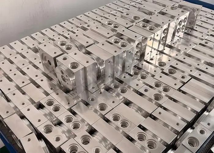
A hydraulic manifold block is typically a machined body containing a network of internal passages. External ports connect those passages to hoses, pipes, fittings, valves, or other hydraulic components.
Some passages carry fluid from the pump to a valve. Others connect the valve to an actuator or provide a return path to the reservoir. The exact connections depend on the hydraulic circuit.
The block can also include valve cavities, mounting holes, sealing surfaces, and openings needed to manufacture internal passages. These features may look similar from the outside but serve different purposes. A drawing should identify which openings are functional ports and which are intended to be sealed after machining.
How Valves Control Flow, Pressure, And Direction
The manifold provides the connections between components. The valves installed on or in it provide the specified control functions.
A directional control valve changes the path available to hydraulic fluid. A pressure control valve may limit or regulate pressure in part of the circuit. A flow control valve restricts or adjusts flow to influence actuator movement.
Not every manifold contains all of these valves. A simple distribution block may divide or combine fluid flow without actively controlling it. The circuit diagram and component specifications determine what the complete system can do.
The Difference Between A Block And A Complete Assembly
A manifold block is the body that contains the machined passages and interfaces. A complete hydraulic valve manifold may also include cartridge valves, surface-mounted valves, plugs, seals, fittings, and electrical components.
This distinction affects purchasing and inspection. A bare block can be checked for dimensions, passage connections, and specified sealing requirements. A complete assembly may need additional checks for valve installation and circuit function.
Before comparing quotations, confirm whether the supplier is providing only the machined block or also supplying and assembling the associated components.
What Are The Common Types Of Hydraulic Manifolds?
Hydraulic manifolds can be grouped by their function, construction, or valve mounting method. These categories overlap, so a custom manifold may also be a distribution manifold or a cartridge valve manifold.

Distribution Manifolds And Valve Manifolds
A hydraulic distribution manifold connects a supply or return line to multiple ports. It can simplify the routing of fluid between components and reduce the number of separate external connections.
A hydraulic valve manifold includes interfaces for valves that control the circuit. Depending on the design, those valves may be installed directly into cavities or mounted on the block surface.
The distinction is useful when defining a project. A distribution block mainly needs the correct passage connections and ports. A valve manifold also requires compatibility between its cavities or mounting surfaces and the selected valves.
Cartridge Valve And Subplate Manifolds
A cartridge valve manifold contains machined cavities designed to accept cartridge valves. Each cavity has specific dimensions, sealing locations, and passage connections that must match the valve manufacturer’s requirements.
A subplate manifold provides mounting surfaces for valves that attach externally. The mounting pattern, port locations, fastener holes, and sealing areas must match the specified valve interface.
Both designs can be used in compact hydraulic systems. The choice depends on the circuit, available space, maintenance requirements, and the valves selected by the system designer. A cavity or mounting pattern should not be substituted based only on a similar appearance.
What Does A Four-Way Hydraulic Manifold Mean?
The phrase “four-way hydraulic manifold” needs clarification because suppliers may use it differently. In a directional valve description, four-way commonly refers to a valve with four functional connections, often identified as pressure, return, and two working ports.
That description does not automatically mean the manifold has four valve stations or only four external openings. A multi-station block can support several valves, and each station may have its own working connections.
When a drawing or inquiry uses this term, confirm the circuit diagram, valve function, port identification, and number of stations. The required valve positions and flow paths should also be specified.
Standard And Custom Manifold Blocks
Standard manifolds use predefined port arrangements or valve mounting interfaces. They can be useful when the circuit matches an available configuration and when replacement components are readily identified.
A custom manifold block is designed around a particular circuit, installation space, or combination of valves. It may integrate connections that would otherwise require separate blocks and fittings.
Customization provides flexibility, but it also requires clear documentation. The manufacturer needs a complete passage layout, component interfaces, material specification, and acceptance requirements. A hydraulic schematic defines circuit function, while the manufacturing drawing and model define the physical block.
Which Materials Are Used For Hydraulic Manifold Blocks?
Aluminum alloys, steels, ductile iron, and stainless steels are used for hydraulic manifold blocks. Selection depends on pressure, loading, weight, corrosion exposure, fluid compatibility, manufacturing requirements, and the specified component life.
Aluminum Alloys
Aluminum alloys are commonly selected when low weight and machinability are important. They are used in equipment where the manifold must fit within a compact assembly or be carried by a moving machine.
The specific alloy and material condition matter. Thread durability, repeated valve installation, operating temperature, and the strength required around ports and plugs should all be considered.
Aluminum is not automatically suitable for every lightweight design. The selected block geometry, valve interfaces, seals, and operating conditions must be evaluated together.
Carbon Steel And Alloy Steel
Carbon steel and alloy steel are used where the design calls for greater mechanical strength, resistance to demanding loads, or a particular pressure capability.
Steel grades vary in strength, machinability, and response to surface treatment. Material condition and processing history can also affect the finished component. The drawing should identify the required grade and any treatment rather than stating only “steel.”
For applications involving repeated pressure cycles, material selection should be considered alongside passage geometry, wall thickness, and other features that may concentrate stress.
Ductile Iron And Stainless Steel
Ductile iron can be used for manifold bodies where its material properties and manufacturing route meet the application requirements. Cast blanks may allow certain external or internal shapes to be formed before final machining.
Stainless steel may be selected for corrosion exposure or compatibility requirements. Its performance depends on the specific grade and environment. It may also require different machining conditions from aluminum or carbon steel.
For either material, the manufacturer must assess the actual blank quality and required final features. The presence of a suitable material name alone does not establish that a block is fit for a particular pressure or fluid.
How Operating Conditions Affect Material Selection
A material decision should start with the operating environment rather than a general ranking of materials. Relevant factors include maximum working pressure, pressure cycling, temperature, hydraulic fluid, external corrosion exposure, and expected service conditions.
Valve and plug requirements also matter. A component manufacturer may specify suitable cavity materials or installation conditions. Surface treatment can affect corrosion resistance, but it should not be assumed to change the underlying strength of the block.
The system designer should confirm the final material and any verification requirements before production.
What Should Engineers Consider In Hydraulic Manifold Design?
A manifold design must translate the hydraulic circuit into passages and interfaces that can be manufactured, inspected, assembled, and maintained. Flow performance and pressure containment should be considered together with tool access and component compatibility.
Circuit Requirements And Internal Passage Layout
The hydraulic schematic establishes which components must be connected and how the circuit is intended to operate. The physical passage layout then provides those connections within the available block volume.
During layout, each passage should be traced from its source to its destination. Intersections that must connect should be clearly identified, while passages that must remain separate need adequate material between them.
A passage map can help both the designer and the machinist verify the intended connections. It also helps prevent a manufacturing drawing from relying on assumptions that are obvious in the schematic but unclear in the physical model.
Passage Size, Wall Thickness, And Pressure Considerations
Passage dimensions affect flow behavior and pressure loss. A passage that restricts flow more than the circuit allows can contribute to unwanted pressure drop and heat generation. Bends, intersections, and connected components also influence the result.
Wall thickness must account for the material, internal geometry, pressure conditions, and applicable design requirements. The minimum wall between adjacent passages and between a passage and the outside surface should be reviewed.
Drill deviation and machining tolerances also matter. A nominally adequate wall in the model may be reduced by manufacturing variation. The designer and manufacturer should agree on how critical passage locations and remaining material will be controlled.
Valve Cavities, Port Connections, And Sealing Interfaces
Valve cavities must match the selected valve’s dimensional and sealing requirements. The cavity can contain steps, threads, sealing lands, and passage openings that each serve a specific function.
External ports also need complete specifications. Thread designation alone may not define the full sealing arrangement. The drawing should identify the required port form, sealing surface, and compatible fitting or plug.
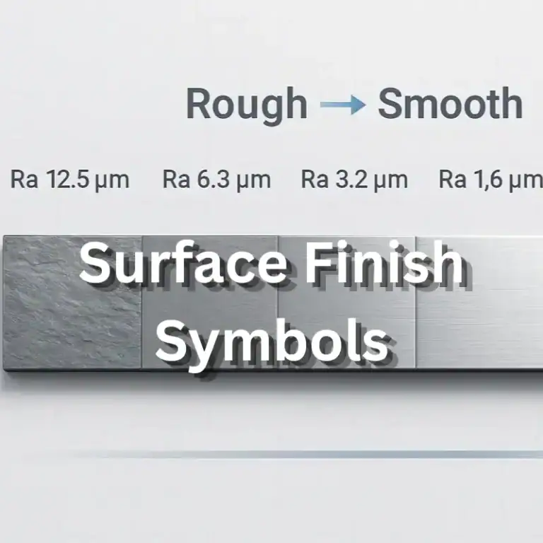
Mounting faces should be specified according to their function. A valve interface may require controls for flatness, surface condition, and hole location. Those requirements should be tied to the valve and seal specifications rather than applied uniformly to every surface.
Drilling Access, Plugs, And Maintenance Space
Internal passages are often produced by drilling from an outside face. Some resulting openings are needed only for manufacturing and must be closed with suitable plugs.
The design should identify these access openings, the required plug type, and the sealing method. The plug and its installation feature must be compatible with the material, operating conditions, and specified pressure requirements.
Space around the block also affects practical use. Valves, fittings, plugs, and fasteners need room for installation and maintenance. A compact layout is valuable only if required components can still be reached and serviced.
How Are Hydraulic Manifold Blocks CNC Machined?
CNC machining forms the external geometry, ports, valve cavities, and internal passages of many manifold blocks. The process plan must also address access-hole sealing, internal burrs, cleaning, and protection of critical surfaces.
Blank Preparation And Datum Planning
A manifold may begin as bar stock, plate, a forging, or a casting, depending on the design and material. The blank must provide enough material for the finished features and any planned machining allowance.
Manufacturing starts by establishing reference surfaces and datums. These references connect features machined from different faces and support consistent inspection later.
The process plan should also consider how the part will be held and repositioned. Inaccurate alignment between setups can affect the relationship between a valve cavity, a port, and the internal passage intended to connect them.
Milling, Drilling, And Cross-Drilled Passages
CNC milling creates external faces, mounting features, pockets, and other accessible geometry. Drilling produces many of the straight internal passages that carry hydraulic fluid through the block.
Cross-drilled passages are made by drilling from different directions so that selected holes meet inside the block. This method can create a connected flow network within a solid body, but it also introduces challenges at the intersections.
Long or small-diameter passages require attention to tool stability, depth, direction, and chip removal. Some geometries may require specialized deep-hole equipment. The appropriate method depends on the passage dimensions, material, and accuracy required by the design.
Valve Cavities, Threads, And Sealing Surfaces
Valve cavities often require several related operations because their steps, diameters, threads, and sealing features must work together. Specialized form tools or dedicated tooling may be used when appropriate for the specified cavity.
Threads should be checked against the required port or component specification. Correct thread engagement is only part of the interface. The related sealing face, counterbore, or seal groove must also meet the drawing requirements.
For surface-mounted valves, machining should maintain the relationship between the mounting pattern and the connected passages. A correctly sized hole in the wrong location can prevent assembly or produce an incorrect connection.
Internal Deburring, Cleaning, And Access-Hole Plugging
When drilled passages intersect, burrs can form at the internal breakthrough edges. Those burrs may be difficult to see or reach, particularly in a complex block with multiple intersections.
The deburring method must suit the material, passage geometry, and accessibility. Possible approaches include mechanical tools, abrasive flow, or other qualified processes. The method should remove unwanted material without damaging sealing features or changing a required passage edge.
After deburring, the block needs cleaning to remove chips, particles, and process residues. Manufacturing access holes are then sealed according to the approved design and process sequence. Plug installation should not introduce contamination or damage the sealing feature.
Surface Treatment And Protection Of Critical Features
A manifold may receive a surface treatment to address corrosion or other environmental requirements. The selected treatment must be compatible with the material, hydraulic fluid, seals, and operating environment.
Treatment can change the dimensions or surface condition of ports, threads, valve cavities, and sealing faces. Drawings should therefore identify treated areas, masked areas, and any features requiring inspection after treatment.
Protective caps or other suitable measures can help prevent damage and contamination during handling and delivery. They should be applied at the appropriate stage in the agreed cleaning and packaging process.
How Is Hydraulic Manifold Quality Verified?
Quality verification should confirm that the block matches its drawing, connects the intended passages, and meets the specified cleanliness and sealing requirements. A complete assembly may require additional functional testing.
Dimensional Inspection And Port Compatibility
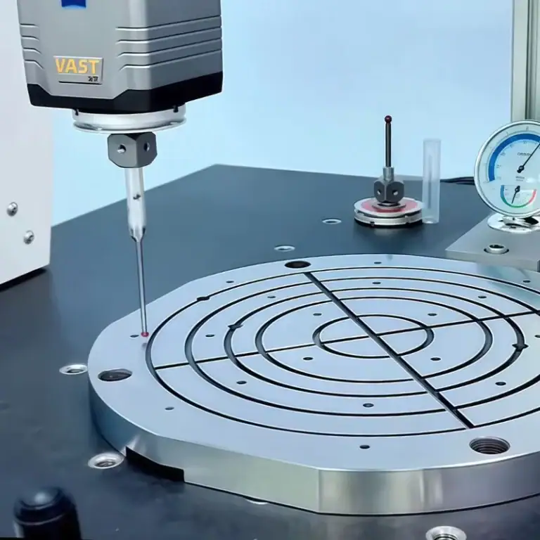
Dimensional inspection should focus on features that affect assembly and function. These include valve cavities, port threads, mounting patterns, sealing faces, and the relationship between external features and internal passages.
| Feature | Typical Inspection Focus |
| External faces and mounting features | Dimensions, datum relationships, and mounting hole positions |
| Valve cavities | Diameters, depths, steps, threads, and sealing features |
| External ports | Port form, threads, sealing surfaces, and location |
| Valve mounting faces | Flatness, surface condition, and port alignment |
| Plug locations | Hole geometry, sealing features, and correct identification |
Inspection methods should match the feature and tolerance. A thread gauge, for example, can check thread conformity but does not by itself verify the complete port sealing geometry.
Passage Connectivity And Internal Cleanliness
A passage should connect the features shown on the drawing and remain separate from passages that are not intended to communicate. Connectivity checks should follow the circuit and passage map.
Internal cleanliness is a separate requirement. A passage can be open and correctly connected while still containing loose particles or residual machining material.
The acceptance plan should define how cleanliness is assessed, including the surfaces or passages covered, the extraction or inspection method, and the required result. A general instruction such as “clean thoroughly” may not give the supplier enough information to establish a measurable acceptance condition.
Pressure And Leakage Testing
Pressure and leakage testing may be specified to assess the integrity of the block or assembled manifold. The test must identify what is being checked, including external sealing and any required separation between internal circuits.
The test procedure should define the medium, pressure, duration, fixtures, and acceptance criteria. Test conditions should follow the applicable design and project requirements. A test pressure used for one product should not be applied to another without engineering review.
The test configuration also matters. Valve cavities, working ports, and manufacturing openings may need appropriate closures or fixtures. Test planning should identify who supplies those items and who is responsible for the test record.
Assembly And Functional Testing When Required
A bare manifold block can pass dimensional and leakage checks without proving that the complete hydraulic circuit works as intended. Functional testing requires the relevant valves and other components to be installed in an appropriate test arrangement.
Depending on the project, verification may include checking valve operation, intended flow paths, and the response of the assembled circuit. The required test scope belongs in the purchase specification.
Separating block acceptance from assembly acceptance helps prevent gaps in responsibility. It also makes clear which results the machining supplier can provide and which must be confirmed by the assembly or system team.
What Should Buyers Provide For A Hydraulic Manifold Quote?
A useful inquiry defines both the physical part and its intended acceptance requirements. Drawings, circuit information, operating conditions, and supply scope allow suppliers to assess feasibility and prepare comparable quotations.
Drawings, Circuit Information, And Operating Conditions
Provide the current engineering drawing and a matching CAD model. The package should identify dimensions, datums, valve cavities, port specifications, sealing features, and the required material.
A hydraulic schematic and passage map are valuable because they show how the internal connections are intended to work. Mark functional ports and manufacturing access holes clearly, including the openings that require plugs.
Operating information should include the relevant working pressure, pressure cycling, temperature, fluid, and external environment. These details help the responsible engineering team evaluate material, sealing, and testing requirements.
Material, Finishing, Cleanliness, And Test Requirements
Specify the material grade and condition, along with any required certification or traceability. Identify the surface treatment, treated areas, masking requirements, and any critical surfaces that must remain untreated.
Cleanliness requirements should state the expected acceptance method and result where applicable. If pressure or leakage testing is required, provide the test specification or request agreement on a suitable procedure before production.
Also identify features with special inspection needs, such as internal intersections or valve sealing lands. Early clarification gives the supplier an opportunity to assess access, tooling, and verification methods before quoting.
Supply Scope, Inspection Records, And Acceptance Criteria
State whether the order covers a bare block, a plugged block, or an assembled manifold. Identify who supplies valves, plugs, seals, and fittings, and who performs any assembly or functional testing.
Confirm the required deliverables, such as material records, dimensional reports, cleaning records, or test results. The quotation should also identify any operations performed by an external partner.
A clear scope makes price comparisons more useful. Two quotations for the same drawing may cover different levels of cleaning, inspection, testing, or assembly. Those differences should be resolved before an order is placed.
FAQs
What Is the Purpose of a Hydraulic Manifold?
A hydraulic manifold connects fluid passages and components within a compact block. It distributes fluid between the pump, valves, and actuators, reducing the need for separate pipes and fittings.
Can You Have Two Manifolds in a Single Hydraulic System?
Yes. A hydraulic system can use multiple manifolds to control different functions or equipment sections. Their connections and pressure requirements must be designed for the same hydraulic circuit.
What Can a Faulty Hydraulic Manifold Cause?
A faulty manifold can cause external leakage, unintended flow between passages, or restricted flow. These issues may lead to pressure loss, overheating, or irregular actuator movement, depending on the fault and circuit.
Conclusion
A hydraulic manifold combines fluid connections within a block and can support valves that control the hydraulic circuit. Its performance depends on the relationship between circuit design, material selection, passage geometry, valve interfaces, manufacturing quality, and verification. Engineers and buyers should define these requirements together so the finished component can be assessed against its intended use.
TiRapid provides custom CNC machining services for precision metal components. Send your hydraulic manifold block drawings, CAD model, material specifications, critical tolerances, and order quantity for a manufacturability review. Include the passage layout, surface treatment, cleanliness, and testing requirements so the machining scope and any additional project needs can be evaluated.