
CNC eccentric turning is widely used to manufacture eccentric shafts, eccentric sleeves, cam components, specialized transmission parts, and precision mechanical connectors. Unlike conventional rotational machining, eccentric components have geometric centers that do not coincide with their rotation axes. Machining these parts requires precise control of eccentricity, axis position, dimensional tolerances, and the relationships between different features. Inaccurate clamping, vibration, workpiece deformation, or datum displacement can prevent the finished component from assembling correctly. For custom precision components, a well-planned eccentric machining process, appropriate workholding, and effective inspection procedures help improve accuracy, reduce scrap rates, and maintain consistency during prototype development and batch production.
Challenges in CNC Eccentric Turning
The main challenge in eccentric machining is maintaining the correct positional relationship between the eccentric features and the design datums. Conventional turning typically uses the workpiece’s rotational axis as the machining reference, whereas eccentric components may contain cylindrical surfaces, holes, or stepped features with different axes. These features may require specialized fixtures, adjusted workpiece positioning, or a combined machining process. The machining strategy should be determined according to the eccentric offset, component dimensions, material properties, and tolerance requirements rather than simply reusing a conventional turning program.
Eccentricity and Coaxial Accuracy
Eccentricity is a critical dimension for determining whether an eccentric component meets its drawing requirements. Machining must control not only the diameter of the eccentric feature but also its center position relative to the specified datum. Components with multiple shaft sections may require coaxiality, positional, or runout tolerances between individual features. The specific acceptance criteria should follow the engineering drawing. If only the outside diameter is inspected while the center position is ignored, the component may still fail during assembly even when its individual dimensions are acceptable.
Why Is Workholding Important?
The workholding method directly affects the accuracy and stability of eccentric machining. If the workpiece is not positioned correctly, or if the fixture’s locating surfaces contain errors, the eccentric offset may shift during machining. Irregularly shaped components, long workpieces with significant overhang, and parts with limited clamping surfaces also face potential deformation caused by clamping and cutting forces. Before machining, manufacturers should verify the locating datums, fixture design, and workpiece rotation. Trial cutting and dimensional inspection can then confirm the actual eccentric position. For high-precision components, stable and repeatable workholding is often more important than simply adjusting cutting parameters.
How Do Different Materials Affect Machining?
Aluminum alloys, carbon steel, stainless steel, copper alloys, and engineering plastics have different cutting characteristics that influence tool wear, cutting forces, thermal deformation, and dimensional stability. Aluminum alloys generally offer good machinability, but thin-walled structures may still deform under clamping or cutting forces. Stainless steel requires attention to work hardening and cutting heat, while engineering plastics require careful consideration of temperature-related dimensional changes. Material selection should account for load-bearing capacity, wear resistance, operating environment, and machining difficulty before appropriate tools, cutting parameters, and inspection procedures are selected.
How to Optimize Eccentric Machining
Precision eccentric components require clearly defined datums, machining sequences, and inspection requirements during process planning. Simple components may be produced by adjusting the workpiece position with suitable workholding, while parts with multiple eccentric axes, complex hole patterns, or tight mating tolerances may require dedicated fixtures, secondary setups, or turn-mill machining. Proper sequencing of roughing, semi-finishing, and finishing operations helps reduce repositioning errors and preserves sufficient allowance for final dimensional adjustments.
How to Choose a Workholding Method
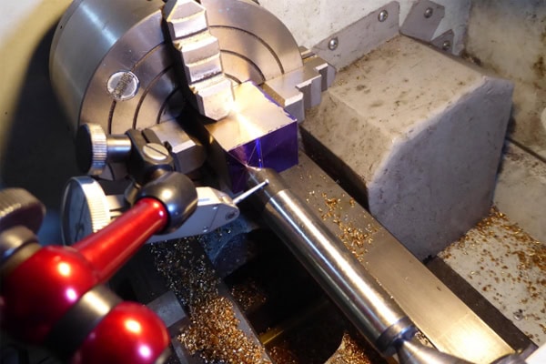
The workholding strategy should be selected according to eccentric offset, component geometry, production volume, and machine capability. Common approaches include eccentric fixtures, dedicated locating tools, adjusted chuck positioning, or the use of additional machining equipment for specific features. Each method offers different levels of positioning accuracy, setup efficiency, and applicability. The decision should not be based on fixture cost alone.
- Define the locating datums: Identify the reference axis, locating face, and eccentric direction from the drawing to ensure repeatable positioning during every setup.
- Match the fixture design: Select suitable workholding according to component geometry, clamping length, and eccentric offset. Use a dedicated fixture when necessary to reduce workpiece movement and positioning errors.
- Verify rotational safety: Eccentric clamping changes the mass distribution during rotation. Evaluate the operating conditions of the workpiece, fixture, and machine, and verify secure clamping before progressively validating spindle speed.
- Control clamping force: For thin-walled sleeves, slender shafts, and easily deformed materials, distribute clamping forces appropriately to avoid significant deformation.
- Verify first-article accuracy: Measure the eccentric offset, critical diameters, and positional relationships after machining the first part. Adjust the fixture or process parameters according to the results.
A suitable workholding strategy improves the consistency of eccentric positioning and reduces repeated setup adjustments. During batch production, manufacturers should also record clamping parameters, fixture condition, and first-article inspection results to establish reusable process standards.
How to Set Cutting Parameters and Machining Sequences
Cutting speed, feed rate, and depth of cut in eccentric machining must be adjusted according to the material, cutting tool, and workholding rigidity. Eccentric rotation may create uneven cutting loads, so conventional turning parameters should not be transferred directly without validation. Roughing should prioritize cutting stability and consistent material removal, while finishing must balance dimensional accuracy, surface quality, and tool condition. For components containing multiple eccentric shaft sections, the machining sequence should follow the datum relationships to minimize positional errors caused by repeated setups. After programming, simulation can be used to check toolpaths, fixture interference, and tool-change movements. First-article machining should then verify the actual results. Parameters should be optimized gradually while monitoring vibration, tool wear, and dimensional changes. Simply increasing spindle speed or feed rate can lead to inconsistent quality.
How to Reduce Vibration and Dimensional Errors
Eccentric workpieces rotate differently from conventional concentric components. Clamping errors, excessive workpiece overhang, insufficient fixture rigidity, and changing cutting loads can all cause vibration and dimensional instability. Manufacturers should select workholding based on component geometry and confirm that the machine, chuck, and fixtures are in good condition. For precision parts, locating datums should be checked before machining, and critical dimensions should be measured promptly after processing to prevent errors from carrying over into subsequent operations.
- Improve system rigidity: Reduce unnecessary workpiece overhang and ensure stable connections between the fixture, tool turret, and workpiece to minimize vibration.
- Control machining allowance: Maintain a consistent allowance distribution to avoid excessive local cutting loads and sudden changes in cutting forces.
- Monitor tool wear: Regularly inspect cutting edges for wear, chipping, and built-up material. Apply tool compensation or replace the tool when necessary.
- Check machine condition: Verify chuck clamping, spindle operation, and tool turret positioning. Stop the machine and investigate if abnormal vibration occurs.
- Establish in-process inspection: Measure eccentricity and positional dimensions after first-article machining and critical operations. Correct deviations promptly before nonconforming parts proceed to the next stage.
A stable machining environment and standardized process controls help reduce rework and improve consistency between production batches. If dimensional errors persist, investigate the locating datums, fixture accuracy, machine condition, and program settings before making further adjustments.
Inspection and Custom Sourcing for Eccentric Components
Quality acceptance for eccentric components should not rely solely on outside diameter and length measurements. Depending on the drawing, inspection may also need to verify eccentric offset, axis position, radial runout, and other critical tolerances. The inspection plan should match the component geometry and required precision and should be agreed upon during the quotation stage to avoid conflicting acceptance criteria after machining. For custom orders, complete drawings, material information, production quantities, and inspection requirements help the manufacturer evaluate process difficulty, fixture requirements, machining time, and overall cost.
How Should Eccentric Dimensions Be Inspected?
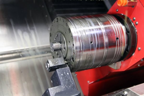
Inspection should follow the datums specified in the engineering drawing, using suitable instruments and measurement methods. Micrometers can measure outside diameters, while dial indicators combined with appropriate locating fixtures can check runout at specific locations. Coordinate measuring machines may be used to verify more complex geometric relationships. Eccentricity, radial runout, and coaxiality are not identical characteristics, so a single measurement cannot replace every required tolerance check. For batch production, first-article inspection, in-process sampling, and final inspection records should be maintained, with consistent measurement locations, datum settings, and acceptance rules. If the component must mate with other parts, its assembly condition should also be evaluated according to the drawing requirements. This helps prevent situations in which individual dimensions pass inspection but the component still performs poorly in the assembled system.
How to Choose a CNC Eccentric Machining Supplier
When sourcing precision eccentric components, a supplier’s process engineering capability, experience in fixture design, and available inspection equipment can directly affect project timelines and finished quality. Buyers should provide sufficient technical information and clarify critical dimensions and acceptance criteria before requesting a quotation.
- Provide complete engineering drawings: Specify the eccentric offset, critical diameters, axis relationships, dimensional tolerances, and surface roughness. Include a 3D model when necessary.
- Specify materials and quantities: Confirm the material grade, heat-treatment condition, prototype quantity, and expected production volume to support process planning and cycle-time evaluation.
- Confirm fixture and inspection requirements: For special eccentric geometries, discuss whether dedicated fixtures are needed and how eccentricity and runout will be measured and accepted.
- Compare total quotation costs: Consider materials, programming and setup, fixture investment, machining time, inspection, and post-processing rather than focusing exclusively on unit price.
- Evaluate technical communication: Choose a machining provider that can explain process limitations, offer design-for-manufacturability recommendations, and clearly describe its quality control procedures.
When requesting a quotation from CNC machining providers such as TiRapid, submit the component drawings, material requirements, order quantities, and acceptance criteria so the team can evaluate feasible machining routes and quotation conditions. Confirming workholding methods, critical dimensional inspection, and delivery requirements in advance can reduce prototype revisions, improve batch consistency, and help ensure that custom eccentric components meet the assembly and operating requirements of the intended equipment.
















