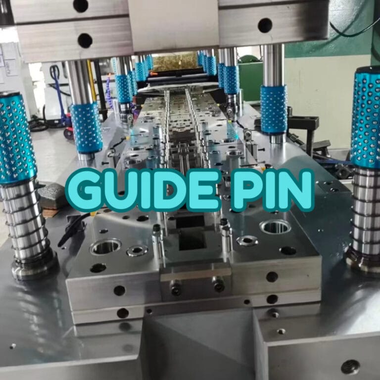
Guide pins are simple components, but they play a critical role in mold alignment, repeatable positioning, and long-term tooling stability. In injection molds, die sets, fixtures, and precision assemblies, a properly designed guide system helps the moving and fixed sections meet in the correct position during every cycle.
This guide explains how a guide pin works, the main guide pin types, guide pins and bushings, fit and clearance, materials, mold layout, wear causes, lubrication, maintenance, and selection. It also explains where a dowel pin, threaded guide pin, or rolling guide system may be more appropriate.
What Is A Guide Pin?
A guide pin is a precision cylindrical component used to align two moving or mating sections of a mold, die, fixture, or mechanical assembly. It normally works with a matching guide bushing to control movement and help the two sections return to the same position repeatedly.
How A Guide Pin Works With A Guide Bushing
A guide pin normally enters a guide bushing as the mold begins to close. The pin and bushing create a controlled sliding relationship that guides one mold half toward the other before the mold reaches its fully closed position.
The guide bushing provides a replaceable wear surface around the pin. This is important because allowing the pin to run directly against the mold plate would gradually wear the plate itself, making repair more difficult and expensive.
The system is designed for alignment rather than heavy load carrying. In high-precision injection molds, guide pins provide initial guidance, while taper locks, interlocks, or other locating features may be used to achieve final cavity-to-core alignment under clamping force.
Guide Pin Vs Dowel Pin: What Is The Difference?
A guide pin controls movement between parts that repeatedly open, close, or slide. It is designed to enter a bushing smoothly and usually includes a lead-in or rounded end that helps the components engage during motion.
A dowel pin, by contrast, is mainly used to establish fixed positional accuracy between two parts. Once installed, it normally remains in place and prevents relative movement between plates, blocks, or assemblies.
In a mold, dowel pins may locate plates or inserts during assembly, while guide pins control repeated mold opening and closing. Both improve positioning accuracy, but they solve different mechanical problems.
Why Are Guide Pins Important For Mold Alignment?
Guide pins help a mold close in the intended position by controlling the relative movement of the moving and fixed halves. Correct alignment protects mold components, improves repeatability, and reduces the risk of damage caused by offset or uneven engagement.
Aligning The Core And Cavity During Mold Closing
An injection mold contains core and cavity features that must meet in the correct relative position. If one mold half approaches the other at an angle or lateral offset, delicate shutoffs, slides, inserts, or parting-line features may be damaged.
Guide pins enter their bushings before the molding surfaces fully engage. This limits unwanted lateral movement and helps the mold halves approach each other along the intended path.
For molds with very tight shutoffs or complex side actions, guide pins alone may not provide enough final alignment accuracy. Additional precision locating elements are often used closer to the cavity.
Maintaining Positioning Accuracy And Repeatability
Injection molds may open and close thousands or millions of times during their service life. The guide system must therefore provide stable, repeatable motion through many cycles.
Consistent guidance helps maintain the relationship between cavity, core, inserts, ejector systems, and other mold components. This becomes especially important when molding parts with tight parting lines or features positioned across multiple inserts.
Repeatability also reduces variation caused by the mold halves approaching each other differently from cycle to cycle.
Reducing Side Load, Wear, And Mold Damage
Misalignment creates side loads. These forces can wear guide bushings, scratch guide pins, damage shutoff surfaces, or place stress on slides and other mold mechanisms.
A properly selected guide pin and bushing system reduces these risks by controlling movement before critical molding surfaces touch.
However, guide pins should not be treated as the only structural element resisting large side loads. If the mold design produces significant lateral force, dedicated locks or supporting features should manage those loads.
What Are the Main Types Of Guide Pins?
Guide pins are available in several designs depending on mounting method, available space, alignment requirement, load, and service environment. The most common styles include straight, headed, threaded, tapered, and rolling guide systems.
Straight And Headed Guide Pins
Straight guide pins have a simple cylindrical body and are commonly installed by press fit into a mold plate. Their simple geometry makes them suitable for many standard molds and die sets.
Headed guide pins include an enlarged shoulder or head that helps control installation depth and provides positive retention. They can be useful where the designer wants a clear axial stop during assembly.
The choice between straight and headed designs usually depends on mold plate thickness, installation method, service access, and the guide component standard being used.
Threaded Guide Pins And Bolt-Fixed Guide Pins
A threaded guide pin includes an external threaded section or another mechanical fastening feature. Instead of relying entirely on press fit, it can be installed, adjusted, or replaced using a threaded connection.
Threaded designs may be useful when repeated disassembly is expected or when access makes a conventional interference fit less practical. They can also be used in fixtures or specialized assemblies outside injection molds.
The threaded region must not weaken the guiding section or introduce looseness. The locating diameter, thread position, shoulder, and tightening method should be designed so the pin remains concentric and stable during operation.
Tapered And Self-Locating Guide Pins
Tapered or self-locating pins use a tapered geometry to help components enter alignment as they move together. They can compensate for small initial offsets more smoothly than a sharp cylindrical engagement.
These designs are often used where assembly guidance is important, but their function should not be confused with high-precision taper interlocks used for final mold alignment.
The taper angle, contact length, and wear condition all influence repeatability. Excessive clearance or worn taper surfaces can reduce locating accuracy over time.
Ball-Bearing And Rolling Guide Systems
Rolling guide systems use balls or rollers between the guide post and bushing to reduce sliding friction. They are common in certain die sets, stamping tools, and precision guiding mechanisms.
Compared with conventional sliding guide pins, rolling systems can provide smooth motion and lower friction, especially where rapid repeated movement is required.
They are not automatically the best option for every injection mold. Cost, contamination, loading direction, maintenance, and the operating environment should be considered before selecting a rolling guide arrangement.
How Do Guide Pins And Bushings Fit Together?
Guide pins and bushings require two different fit conditions: a secure installation fit where the component is mounted into the mold plate, and a controlled running clearance where the pin slides through the bushing. Mixing these two requirements can cause either looseness or seizure.
Running Clearance Between The Guide Pin And Bushing
The guide pin must move through the bushing without binding. A small running clearance allows for lubrication, thermal expansion, manufacturing tolerance, and minor operating variation.
Too little clearance can cause sticking, heat, scoring, or seizure. Too much clearance allows lateral movement and reduces the alignment benefit of the guide system.
The correct clearance depends on guide diameter, mold size, precision requirement, materials, operating temperature, and the guide component supplier’s recommended fit. Standard guide pin and bushing sets should normally be used according to their specified tolerance system.
Interference Fit For Pin And Bushing Installation
The mounting end of a guide pin is often press-fitted into a mold plate. The bushing may also be installed with an interference fit or retained by a shoulder, flange, or mechanical fastener.
The purpose is to prevent the guide component from moving inside the plate during mold operation.
An excessive interference fit can distort the pin, bushing, or surrounding plate. Insufficient interference can allow the component to loosen. Bore accuracy, surface finish, plate material, and actual component diameter therefore need to be controlled.
Diameter, Length, And Engagement Requirements
Larger guide pins generally provide greater stiffness, while sufficient engagement length helps the pin stabilize the mold halves before critical surfaces contact.
The pin should engage the bushing early enough during closing to guide the mold safely, but unnecessary length can increase cost, friction, and the risk of interference with mold handling.
Diameter and length should be selected together based on mold size, weight, alignment demand, plate spacing, and expected side loading.
Lead-In, Chamfers, And Smooth Mold Engagement
Guide pins commonly use a rounded or tapered lead-in at the entering end. This helps the pin find the bushing opening when small positional differences exist.
A sharp edge would be more likely to strike the bushing face, damage the edge, or prevent smooth engagement.
The bushing entrance may also include an appropriate chamfer. Together, these features improve mold closing behavior without replacing the need for correct overall alignment.
What Materials Are Used for Guide Pins?
Guide pin material must provide hardness, wear resistance, dimensional stability, and enough toughness to survive repeated mold cycles. Hardened alloy and tool steels are the most common choices, while stainless steel and specialized wear materials are used for specific environments.
Hardened Tool Steel And Alloy Steel
Hardened steels are widely used because they offer a strong balance of wear resistance, toughness, and manufacturability.
The guide surface is usually hardened and ground to achieve controlled diameter, roundness, and surface finish. A smooth surface reduces friction and slows bushing wear.
The exact steel grade depends on the guide system standard and supplier, but heat treatment must be controlled carefully. Excessive brittleness can cause cracking, while insufficient hardness accelerates wear.
Stainless Steel For Corrosive Environments
Stainless steel guide pins may be considered when molds operate in humid, corrosive, or clean environments where rust prevention is important.
However, stainless steel grade selection still needs to consider hardness and galling resistance. A corrosion-resistant alloy that is too soft may not provide adequate wear life.
In some cases, corrosion protection is achieved through surface treatments rather than changing the entire guide pin material.
Carbide For High-Wear Applications
Carbide offers extremely high hardness and wear resistance and may be used in specialized guide or locating components.
Its disadvantage is lower toughness compared with many hardened steels. Impact, edge chipping, and manufacturing cost must therefore be considered.
For most standard injection molds, hardened steel guide components provide a more practical balance of cost and performance. Carbide is usually reserved for applications where severe wear justifies the additional expense.
Hardening, Nitriding, And Surface Treatments
Heat treatment improves guide pin hardness and wear resistance. Grinding after hardening helps achieve the required dimensional accuracy and surface quality.
Nitriding, hard chrome, or other surface treatments may be used in some guide systems to reduce wear or improve corrosion resistance.
The treatment must be compatible with the bushing material. Pairing two surfaces incorrectly can increase galling or accelerate wear instead of reducing it.
How Should Guide Pins Be Arranged In A Mold?
Guide pin arrangement affects mold stability, orientation, and closing behavior. The layout should provide balanced guidance around the mold while preventing incorrect assembly and leaving sufficient space for cavities, slides, cooling lines, and other mold systems.
Number And Position Of Guide Pins
Many mold bases use four guide pins positioned near the corners to support stable alignment over a broad area.
The pins should be spaced far enough apart to resist angular movement effectively. Placing them too close together reduces their ability to control mold rotation.
Actual layout depends on mold size and internal features. Cooling channels, ejector systems, slides, and inserts may require the guide positions to be adjusted.
Symmetrical Vs Asymmetrical Guide Pin Layout
A perfectly symmetrical guide pin arrangement can create a risk of incorrect mold orientation during assembly if both halves appear interchangeable.
For this reason, designers may intentionally offset one guide position or use a different guide arrangement so the mold can only be assembled in the correct orientation.
This approach is sometimes described as mistake-proofing or poka-yoke. It reduces the chance of assembling plates incorrectly during mold maintenance.
Preventing Incorrect Mold Orientation
Orientation control is particularly important when cavity features, cooling connections, ejector systems, or slides are not symmetrical.
One offset guide pin, a different pin diameter, or another dedicated orientation feature can prevent the mold plates from being installed incorrectly.
The method should be obvious and robust. Relying on operator memory alone is less reliable than designing the mold so incorrect assembly is physically difficult or impossible.
Guide Pin Placement For Large And High-Precision Molds
Large molds have greater mass and may experience more plate deflection. Their guide system must therefore provide sufficient stiffness and engagement.
High-precision molds may also use additional taper locks or interlocks close to the cavity to control final alignment.
Guide pins should provide broad initial guidance, while precision locating features handle the final relationship where cavity alignment is most critical.
What Causes Guide Pin Wear And Alignment Problems?
Guide pin wear usually comes from poor alignment, incorrect clearance, contamination, inadequate lubrication, surface damage, or excessive side loading. Identifying the cause is more effective than repeatedly replacing worn pins without correcting the underlying problem.
Poor Fit And Insufficient Clearance
A guide pin that is too tight in its bushing creates excessive friction. The result can be heat buildup, scoring, sticking, or rapid surface damage.
A loose fit causes the opposite problem. The mold can move laterally before closing, reducing alignment accuracy and increasing wear on other components.
When abnormal wear appears, both the pin and bushing dimensions should be measured rather than assuming only one component is defective.
Misalignment And Uneven Side Loads
If mold plates, guide bores, or guide components are not coaxial, the pin contacts one side of the bushing more heavily.
This creates uneven wear patterns and can gradually enlarge the bushing clearance.
Strong side loads may also come from slides, angled shutoffs, poorly balanced mold weight, or incorrect machine mounting. The root source of side loading should be corrected rather than expecting the guide pin to absorb it indefinitely.
Contamination, Corrosion, And Surface Damage
Dust, plastic residue, metal particles, or degraded lubricant can enter the guide system and act as abrasive contaminants.
Rust or corrosion damages the polished guiding surface and increases friction.
Small scratches may seem minor, but repeated sliding can turn surface damage into accelerated wear. Keeping the mold clean during production and maintenance is therefore important.
Inadequate Lubrication And Guide Pin Grease
Lubrication reduces friction between the guide pin and guide bushing. Without appropriate lubrication, sliding surfaces can wear rapidly or develop galling.
Guide pin grease should be compatible with the mold temperature, materials, and production environment. Excess grease should also be avoided because it can collect contamination or migrate toward sensitive molding surfaces.
Some guide systems use self-lubricating bushings or supplier-specified lubricants. Maintenance should follow the actual component design rather than applying the same grease practice to every mold.
How To Maintain Guide Pins And Bushings
Regular guide pin maintenance focuses on cleanliness, lubrication, surface condition, and clearance. Small maintenance actions can prevent wear from developing into mold misalignment, damaged cavities, or unplanned machine downtime.
Cleaning And Routine Inspection
Guide pins should be cleaned during scheduled mold maintenance and checked for scratches, scoring, discoloration, corrosion, or abnormal wear patterns.
Bushings should also be inspected internally. A pin may still look acceptable while the bushing has become oval or oversized.
Unusual marks on only one side of a pin can indicate misalignment or side loading and should not simply be polished away without investigation.
Choosing And Applying Guide Pin Grease
Use a lubricant recommended for the operating temperature and guide component material.
A thin, controlled layer is normally more useful than excessive grease. Too much lubricant can trap debris and make inspection difficult.
The maintenance interval depends on cycle count, operating speed, temperature, cleanliness, and bushing design. High-cycle molds may require more frequent inspection than low-volume tooling.
Checking Wear, Clearance, And Surface Condition
Visual inspection should be supported by measurement when wear is suspected.
Guide pin diameter, bushing bore, and running clearance can be compared with the original component specification.
If the clearance has increased significantly, replacing only the pin may not restore proper guidance. The pin and bushing should be treated as a working pair.
When To Replace Guide Pins Or Bushings
Replacement is appropriate when guide surfaces show deep scoring, severe wear, corrosion, deformation, or clearance outside the acceptable range.
A damaged bushing should not be ignored simply because the guide pin has been replaced. A worn bushing can quickly damage a new pin.
Repeated failures usually indicate a deeper alignment or loading problem. Repair should therefore include root-cause analysis when wear returns unusually quickly.
How To Choose The Right Guide Pin For Your Application
The right guide pin should match the mold size, alignment requirement, cycle rate, mounting method, environment, and maintenance strategy. Selecting a standard component is often economical, but custom guide pins can solve special geometry, load, or installation requirements.
Match Load, Precision, And Cycle Requirements
Start with mold size and moving mass. Larger or heavier tooling usually requires stiffer guide components and suitable engagement length.
Precision requirements also matter. Standard guide systems may be sufficient for general alignment, while high-precision molds may require additional cavity-level interlocks.
Cycle frequency affects wear expectations. High-cycle tooling benefits from hardened surfaces, consistent lubrication, and easy-to-replace bushings.
Select The Correct Pin Type And Bushing System
A standard straight guide pin works well for many molds. Headed or threaded guide pins may be more convenient where specific retention or maintenance access is required.
Guide pins and bushings should normally be selected as a compatible system rather than combining unrelated components.
If rolling pin guides or ball-bearing guide systems are being considered, confirm that their precision, load capacity, contamination resistance, and maintenance requirements fit the application.
Choose Material, Hardness, And Surface Finish
Guide surfaces should be hard enough to resist wear while maintaining sufficient toughness.
Surface finish is equally important because rough guiding surfaces increase friction and accelerate bushing wear.
Material and treatment should also consider corrosion risk, temperature, lubrication, and the mating bushing material.
Decide Between Standard And Custom Guide Pins
Standard guide pins reduce cost and replacement time because sizes, bushings, and spare parts are readily available.
Custom guide pins are useful when the mold requires unusual length, shoulders, threads, diameters, installation features, or specialized materials.
Customization should solve a real design constraint. Using unnecessary special components can increase lead time and make future maintenance more difficult.
FAQs
Can A Guide Pin Control Final Injection Mold Alignment By Itself?
Not always. Guide pins provide general mold guidance, but high-precision molds often use taper locks or interlocks near the cavity for final alignment under clamping force.
Should Guide Pins And Bushings Be Replaced At The Same Time?
Not necessarily, but both should be inspected and measured. Replacing a worn pin while leaving an oversized or damaged bushing may cause rapid wear and fail to restore correct alignment.
Can Guide Pins Run Without Grease?
Some self-lubricating guide systems can operate with little or no added grease, but conventional sliding systems normally require suitable lubrication. Always follow the component supplier’s recommendation.
How Can I Tell If Guide Pin Wear Is Caused By Misalignment?
Uneven wear, scoring concentrated on one side, repeated bushing damage, or a guide pin that binds only during part of the closing stroke can indicate misalignment. Plate and bore alignment should be checked before replacing components.
Conclusion
Guide pins are fundamental to reliable mold movement because they control initial alignment, repeatable positioning, and smooth engagement between moving mold sections. Their performance depends on more than pin diameter alone: bushing fit, material hardness, engagement length, layout, lubrication, surface condition, and side loads all affect accuracy and service life. A well-designed guide system reduces wear and helps protect more expensive mold components.
At TiRapid, we provide precision CNC machining and manufacturing services for custom mold components, guide pins, bushings, inserts, and other precision parts. Our team combines material selection, controlled machining, dimensional inspection, and practical manufacturing support to produce accurate components for prototypes, tooling, and production applications.