
Components used in lithography equipment must meet more than basic shape and dimensional requirements. Slight deviations in mounting hole positions, uneven locating surfaces, or residual burrs can affect assembly accuracy. Semiconductor equipment demands high standards for precision, stability, and surface quality, particularly for custom parts with complex geometries, precision holes, and slots. For equipment manufacturers, the real challenge is turning drawing specifications into consistent machining results while reducing prototype rework and ensuring that both prototypes and production batches meet assembly requirements. A well-planned CNC machining solution helps precision components move more smoothly from design to practical application.
What Are the Main CNC Machining Challenges for Lithography Equipment Components?
Lithography equipment contains mounting plates, support brackets, connectors, locating components, and other precision parts. Although these components vary in size, they must fit accurately within the equipment structure. Machining challenges often involve complex profiles, critical hole positions, and dimensional relationships between multiple mounting surfaces. Checking individual dimensions alone is not enough if the overall positioning relationships are overlooked.
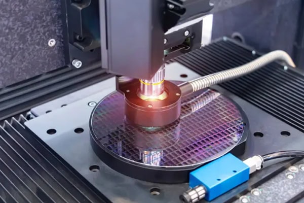
How to Control Machining Accuracy for Precision Lithography Components?
Precision machining requires critical dimensions to be addressed at each stage of production. Different components have different tolerance requirements, so machining methods, fixturing, toolpaths, and inspection procedures should be selected according to the part’s geometry.
- Precision hole machining: Meeting the specified hole diameter is only the starting point. Hole spacing, positional accuracy, and relationships to reference datums must also comply with the drawing to prevent misalignment with mating components.
- Complex profile machining: Plan toolpaths for irregular edges, deep grooves, and stepped structures to reduce localized overcutting and tool interference.
- Thin-wall component machining: Control clamping force and cutting loads to minimize deformation during machining and dimensional changes after unclamping.
- Multi-face machining: Arrange the machining sequence in advance to reduce repeated setups and repositioning errors.
These details may seem minor, but they can directly affect final assembly. Defining critical dimensions, locating datums, and inspection methods before production helps reduce repeated adjustments and improve dimensional consistency.
How to Maintain Surface Quality in Semiconductor Lithography Components?
Surface quality affects more than appearance. It also influences component fit, cleanliness, and subsequent finishing operations. For parts used in controlled environments, burrs, residual chips, machining scratches, and unsuitable surface treatments can increase cleaning requirements and complicate assembly.
Finishing, edge deburring, and cleaning should be included in the machining plan. If the drawings specify surface roughness, special treatments, or packaging requirements, acceptance criteria should be confirmed before production. This helps prevent additional processing after machining and reduces the risk of delivery delays.
How to Reduce Fixturing Errors in Custom Lithography Equipment Parts?
Components with multiple mounting faces, angled holes, or specialized slots may require several machining operations. Every new setup introduces the possibility of positioning variation. Planning datum transitions and maintaining clear positional relationships between critical surfaces can reduce errors caused by repeated alignment. For components with tight tolerances, it is also important to evaluate whether clamping could affect thin walls or precision mating surfaces, preventing parts from passing inspection while clamped but changing dimensions after removal.
How to Select Materials and Machining Processes for Custom Lithography Components?
Material selection affects component weight, rigidity, corrosion resistance, and machinability. The easiest material to machine is not necessarily the most suitable for lithography equipment. Actual operating conditions and drawing specifications must also be considered. Once the material is confirmed, tool selection, fixturing, machining sequence, and surface finishing should be planned together to avoid problems caused by mismatched materials and processes.
What Materials Are Commonly Used for Lithography Equipment Components?
| Material Type | Typical Component Applications | Key CNC Machining Considerations |
| Aluminum alloys | Mounting plates, support brackets, lightweight connectors | Thin-wall deformation, burrs, and surface finishing |
| Stainless steel | Corrosion-resistant connectors and structural components | Cutting heat, tool wear, and chip evacuation |
| Titanium alloys | Specialized corrosion-resistant or lightweight components | Cutting parameters and temperature control |
| Engineering plastics | Insulating parts and selected functional components | Thermal deformation, clamping force, and dimensional changes |
Machining behavior can vary between grades, so the applications in this table are intended as a preliminary reference. Actual material selection should follow the part drawings, technical specifications, and operating requirements. If anodizing, passivation, or other surface treatments are required, dimensional requirements after treatment should also be confirmed in advance.
How to Plan CNC Machining Operations for Complex Lithography Parts?
Complex components may include multiple flat surfaces, holes, steps, and localized slots. An unsuitable machining sequence can increase the number of setups and affect the consistency of critical dimensions.
- Establish machining datums: Identify the primary locating surfaces and critical holes to provide consistent dimensional references for subsequent operations.
- Allocate machining allowance: Leave sufficient material during rough machining before finishing precision mating surfaces and critical holes.
- Check tool accessibility: Evaluate tool clearance for deep grooves, narrow slots, and special profiles to reduce interference and chip evacuation problems.
Process planning is especially important when components have complex geometries or tight tolerances. A well-defined toolpath, fixturing strategy, and inspection sequence can reduce program changes and repeated trial cuts while improving production efficiency.
What Information Is Needed for Custom CNC Machining of Lithography Components?
Complete technical information helps the machining team evaluate process complexity, material requirements, and lead times more accurately. When requesting a quotation or prototype, prepare the following details:
- Part drawings or 3D models: Include overall dimensions, hole positions, tolerances, and special features.
- Material and surface requirements: Specify the material grade, surface roughness, and required finishing processes.
- Mating dimensions and installation datums: Identify interfaces with other components to clarify assembly requirements.
- Quantity and delivery schedule: State the prototype quantity, expected production volume, and target delivery date.
- Special inspection requirements: Indicate whether dimensional inspection reports or specific acceptance criteria are required.
Clear technical information makes it easier to develop a suitable machining plan. If the design is still being revised, identify the current drawing revision and any dimensions that remain subject to confirmation. This helps reduce repeated communication and misunderstandings during production.
How to Ensure Quality and Batch Consistency in CNC Machining for Lithography Equipment?
Precision components must not only pass inspection during prototyping but also maintain consistent quality in repeat production. Tool wear, fixturing changes, and material variations can gradually affect dimensions. Scheduling first-article approval, in-process inspection, and final inspection at appropriate stages helps identify deviations early and prevents defects from affecting an entire batch.
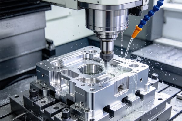
What Inspection Items Are Required for Precision Lithography Components?
| Inspection Item | Main Checks | Quality Control Purpose |
| Dimensional tolerances | Overall dimensions, hole diameters, step heights | Verify compliance with drawings |
| Positional accuracy | Hole spacing, hole locations, datum relationships | Reduce positioning errors and assembly interference |
| Geometric accuracy | Flatness, perpendicularity, and related requirements | Maintain stable mounting and mating surfaces |
| Surface quality | Roughness, burrs, and scratches | Meet specified surface requirements |
| Cleaning and packaging | Chips, oil residue, and protective packaging | Reduce contamination risks during transportation |
Inspection methods and acceptance criteria should follow the engineering drawings and technical specifications. For components produced repeatedly, maintaining records of critical dimensions also helps compare production batches and supports traceability.
How to Identify Dimensional Deviations During CNC Machining?
If all inspections are postponed until production is complete, several parts may already be affected by the time a problem is discovered. A more effective approach is to inspect critical dimensions during production and recheck relevant features after tool changes or process adjustments.
- Inspect mounting holes, locating holes, and critical external dimensions to identify positional or dimensional changes early.
- Recheck thin-wall components after unclamping to detect deformation that may not be apparent during fixturing.
- Pay attention to deep grooves, hole edges, and corners, removing burrs and checking for localized surface defects.
- When deviations occur, investigate tool wear, fixture positioning, and machining programs before the issue affects subsequent parts.
Addressing problems during machining is generally more efficient than repairing an entire batch after production and helps maintain a more predictable delivery schedule.
How to Move Lithography Components from Prototyping to Batch Production?
Prototype machining is not just about confirming that a component can be manufactured. It also verifies critical dimensions, assembly relationships, and surface requirements. Once a prototype passes inspection, the validated programs, fixturing methods, and inspection procedures should be carried forward into production to reduce differences between prototypes and batch-manufactured parts.
- Prototype machining: Manufacture parts using the approved drawings and inspect critical dimensions and special features.
- Assembly verification: Check installation positions and mating conditions to identify design details that may need adjustment.
- Process optimization: Refine toolpaths, fixturing methods, or machining sequences based on prototype results.
- First-article approval: Recheck critical dimensions and surface conditions before batch production begins.
- Batch inspection: Monitor dimensions susceptible to tool wear or fixturing changes and retain the necessary inspection records.
For components with recurring production requirements, validated machining processes and clearly defined inspection criteria help maintain batch consistency and make repeat orders easier to manage.
CNC machining for lithography equipment components requires careful control of precision dimensions, complex geometries, material properties, and batch consistency. Confirming drawings, tolerances, surface treatments, and inspection requirements in advance, followed by effective process planning and in-process checks, can reduce rework and improve component fit in semiconductor equipment. TIRAPID provides CNC machining services for lithography equipment and precision semiconductor components, supporting custom manufacturing, prototype development, and batch production according to drawings and technical specifications.
















