
In plastic CNC machining, chip evacuation is an important factor that affects machining quality. Compared with metal materials, most engineering plastics have relatively low thermal conductivity, relatively low hardness, and limited heat deflection temperatures, so the heat generated during cutting is not easily conducted away quickly through the workpiece itself. As a result, if chips remain near the tool and the workpiece for a long time, they not only hinder heat dissipation in the cutting zone, but can also cause repeated cutting of chips, tool wrapping, scratches on the machined surface, and localized softening of the material. For plastics such as nylon, ABS, POM, PC, acrylic, and PE, the chip forms produced by different materials also differ markedly: some materials tend to form continuous ribbon-like chips, while others tend to produce fine debris or powder.
If chip evacuation is inadequate, these chips gradually accumulate inside the tool, the flutes, deep cavities, and blind holes, making the machining state unstable. In actual plastic CNC machining, whether chips can be evacuated in time is directly related to cutting-heat control, protection of the machined surface, dimensional accuracy, and tool life. This is especially true for thin-walled parts, deep-cavity parts, narrow-slot parts, and continuous batch production, where the impact is more pronounced if chips cannot leave the cutting zone promptly. Therefore, arranging chip evacuation properly and adjusting it in combination with tool geometry, feed parameters, depth of cut, and part structure is an important measure for improving the machining quality of plastic parts.
Cutting Heat in Plastics Is Carried Away Mainly by the Chips
The thermal conductivity of plastic materials is generally markedly lower than that of metals. During cutting, metals such as aluminum alloys and steel can transfer and release part of the heat through the workpiece, the tool, and the surrounding environment, whereas plastics conduct heat relatively slowly, so cutting heat tends to concentrate near the tool tip, the cutting edge, and the machined surface. In plastic CNC machining, therefore, the chips play an important role in heat dissipation. When chips can leave the cutting zone quickly after being formed, the large amount of cutting heat they carry is also removed, lowering the temperature in the contact zone between the tool and the workpiece. If chips remain around the tool while new chips keep entering the machining zone, localized heat buildup tends to occur. As the temperature continues to rise, some thermoplastics soften, deform, or even melt locally, and chips may re-adhere to the tool or the workpiece surface. This is more noticeable when machining materials such as nylon, ABS, and polyethylene. If the cutting temperature keeps rising, plastic tends to adhere to the tool surface, the sharpness of the cutting edge declines, and friction and heat generation then increase further, causing defects such as burrs, stringy marks, and adhesive residue on the machined surface.
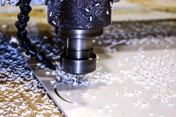
Chip Retention Tends to Damage the Machined Surface
Plastic parts generally have relatively high requirements for appearance and surface quality, especially transparent parts, cosmetic parts, and precision parts that are assembled directly. When chips are not evacuated in time, they tend to stay between the tool and the already machined surface and are squeezed and rubbed again during tool movement, producing unnecessary surface damage.
Common manifestations include the following:
Scratches and scuffing: Hard debris produced by materials such as glass-fiber-reinforced plastics and PC, if left in the machining zone, may be carried back into the cutting path by the tool, leaving scratches, scuff marks, or fine indentations on the machined surface.
Melt adhesion: Thermoplastic chips soften easily when heated. If high-temperature chips do not leave the machining zone in time, they may re-adhere to the workpiece surface, forming adhesive residue, raised spots, or irregular deposits.
Fogging and white spots: Transparent materials such as acrylic and PC are sensitive to machining temperature and friction. After high-temperature chips contact the machined surface for a long time, localized fogging, whitening, or reduced transparency may occur.
Overheating and discoloration: Some plastics change color at excessive temperatures. If heat keeps accumulating in the cutting zone, localized discoloration such as yellowing or darkening may appear.
These defects not only affect the appearance of the part, but may also increase the follow-up work. If surface scratches, adhesive residue, or melt marks are obvious, reworking, grinding, or polishing is often required, which increases machining time and may also change the original dimensions of the part.
Continuous Chip Wrapping Increases Tool Risk
Different plastic materials produce different chip forms during CNC machining. Nylon, ABS, and some tough plastics tend to form long ribbon-like or stringy chips. If the flute space is insufficient or the airflow cannot carry the chips away in time, chips tend to wrap around the tool, the shank, or even the spindle.
After chips wrap around the tool, the normal cutting state is affected, mainly in the following ways:
Change in tool load: Chips wrapped around the tool increase localized resistance, making the cutting load unstable and prone to vibration, which in turn affects part dimensions and surface quality.
Blocked flutes: Some chips enter the flutes and cannot be evacuated smoothly, and subsequent new chips keep piling up, eventually causing severe chip packing.
Blocked cooling and airflow: Once chips wrap around the tool, compressed air or coolant cannot fully reach the tool tip area, and cutting heat is not easily removed in time.
Abnormal tool wear: When a large amount of chips wraps around the tool, tool rotation is noticeably affected. In severe cases, the tool may chip, break, or even damage the workpiece.
Therefore, for plastic materials that tend to produce continuous chips, special attention should be paid to the flute space and chip evacuation direction of the tool, to avoid letting chips stay near the tool for a long time.
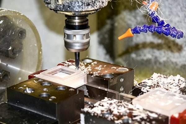
Powder and Debris Tend to Accumulate
For plastic parts with more complex structures such as deep cavities, blind holes, and narrow slots, chip evacuation is generally more difficult than for flat surfaces and shallow grooves. Because the machining zone is deep, chips do not have enough space to escape naturally, and compressed air may not be able to reach the bottom of the hole or cavity directly. Some brittle materials such as acrylic and PC tend to produce fine debris and powder during machining. If this powder keeps settling at the bottom of a deep cavity or blind hole, it may be drawn back into the cutting zone when the tool next enters the area, causing secondary friction. Under certain machining conditions, some plastics may also form fine flake-like or paste-like residue, which adheres more easily to the cavity bottom after mixing with a small amount of coolant or lubricant. This accumulation affects subsequent finishing, especially when finishing needs to use the hole bottom, cavity bottom, or a machined surface as a locating datum; residual chips may change the actual contact position of the tool, causing dimensional deviation. At the same time, cleaning chips from inside deep cavities is also more difficult, and if not handled in time, it will affect the machining quality of the next operation.
Common Measures for Timely Chip Evacuation
In plastic CNC machining, the chip evacuation method should be selected reasonably according to the material, part structure, tool type, and machining parameters. For ordinary milling, compressed air, a dust extraction device, or a suitable cooling method can be used to help chips leave the cutting zone.
Common practices include:
Use compressed air to clean the cutting zone: During machining, compressed air can be used to continuously blow away chips, keeping them away from the tool and the workpiece surface. A common air-pressure range is about 0.4-0.6 MPa, and the actual pressure should still be adjusted according to the equipment, material, and machining state. The airflow should be directed at the bottom of the tool and the chip-producing area, avoiding blowing chips directly onto other precision-machined surfaces.
Adjust cutting parameters reasonably: Feed rate, depth of cut, and spindle speed need to match each other. If the feed is too small, the tool rubs against the material for a long time, which tends to produce a large amount of fine powder or heat; a reasonable chip thickness helps form chips of an appropriate size, making them easier to carry away by the airflow.
Select the tool according to the plastic material: For materials such as nylon and ABS that tend to produce continuous chips, single-flute or two-flute cutters with larger flutes can be selected to provide more chip space. For materials such as glass-fiber-reinforced plastics, both tool wear resistance and chip evacuation performance need to be considered.
Use layered cutting for deep cavities and blind holes: For deep-cavity structures where chip evacuation is difficult, layered cutting, periodic tool retraction, and back-off can be used to provide space for chips to escape, avoiding keeping the tool in the chip accumulation zone the whole time.
Keep the machining area clean: During machining, residual chips around the worktable, fixtures, and workpiece should be cleaned in time to prevent chips that have already been evacuated from being drawn back into the cutting zone. In batch production, it is especially important to check the chip evacuation state regularly.
However, chip evacuation is not a problem that can be fully solved by adjusting a single parameter alone. The number of flutes, helix angle, flute geometry, spindle speed, feed rate, depth of cut, and the cutting characteristics of the material itself all affect chip evacuation. When machining conditions change, the chip form and the workpiece surface state should also be observed in tandem.
Frequently Asked Questions
What problems are mainly caused by not evacuating chips promptly in plastic machining?
When chips remain in the machining zone for a long time, cutting heat accumulates, causing the plastic material to soften, adhere, or even melt locally; residual chips may also be carried back into the cutting path by the tool, forming scratches, scuff marks, and indentations on the machined surface. For materials such as nylon and ABS that tend to produce continuous chips, chips may also wrap around the tool, causing vibration, chip packing, and abnormal wear. For deep-cavity and blind-hole structures, the accumulation of powder and debris also affects the locating and dimensional control of subsequent machining.
Why does plastic machining require more attention to chip evacuation than metal machining?
Plastics and metals differ significantly in thermal conductivity and cutting characteristics. Metals generally have better thermal conductivity, so part of the heat generated during cutting can be transferred away through the workpiece and the tool, whereas most plastics have low thermal conductivity, so cutting heat tends to concentrate near the tool tip and the machined surface. If chips are not evacuated in time, the localized temperature tends to rise, leading to material softening, adhesion, and surface damage. At the same time, plastic chips are not all regular small granules; some materials tend to produce long ribbon-like chips, while others produce powder or fragments. These chips are more likely to wrap and accumulate, so plastic CNC machining generally has higher requirements for chip evacuation.
What is a simple way to judge whether chip evacuation is normal?
It can be judged from the chip form, tool state, machined surface, and cutting sound. Under normal machining, chips can generally leave the cutting zone in time with the tool movement and do not accumulate in large amounts around the tool. If the chips are found to be continuously fine powder or long stringy, or wrap around the tool in large amounts, the tool geometry, cutting parameters, and airflow direction should be checked. At the same time, observe whether the machined surface shows abnormal scratches, scuff marks, whitening, fogging, or melt marks. If the cutting sound gradually becomes dull or the tool vibration increases noticeably, it is also worth checking whether chips are blocking the flutes or accumulating in the machining zone. Through these signs, poor chip evacuation can be detected early and the machining conditions adjusted in time.
Conclusion
In plastic CNC machining, chips can carry part of the cutting heat away from the cutting zone, so their evacuation speed and state directly affect the cutting temperature. For plastic materials with low thermal conductivity and relatively limited heat deflection temperatures, if chips remain for a long time, problems such as material softening, chip adhesion, surface scratching, and tool wrapping tend to occur. For deep-cavity, blind-hole, and narrow-slot machining, special attention should also be paid to the accumulation of debris and powder to avoid residual material affecting subsequent finishing. In plastic CNC machining, a suitable tool should be selected according to the specific material and part structure, and the spindle speed, feed rate, and depth of cut should be adjusted reasonably, while using compressed air, a chip extraction device, or another suitable evacuation method so that chips can leave the tool and the workpiece in time. For continuous and batch production, it is even more important to keep the machining area clean and to check the tool flutes and the residue inside the machined cavities regularly. Good chip evacuation reduces surface damage and abnormal heat generation, and also helps maintain dimensional accuracy and normal tool life. Therefore, when planning a plastic CNC machining process, chip evacuation should be considered together with tool selection, cutting parameters, and part structure, so that the entire machining process remains stable and smooth.
















