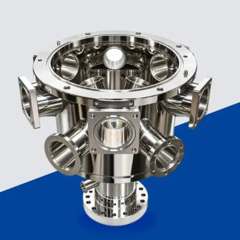
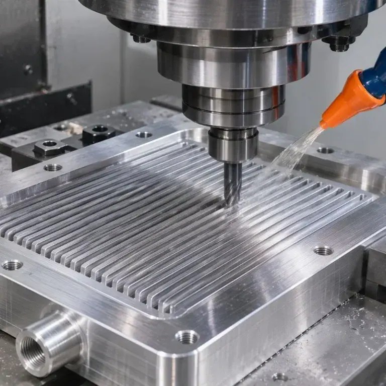
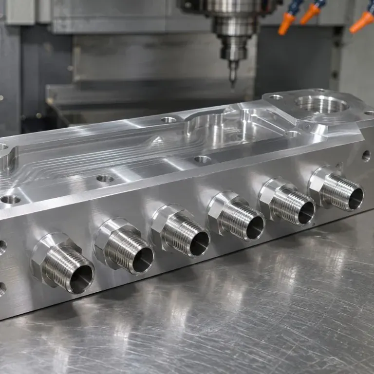
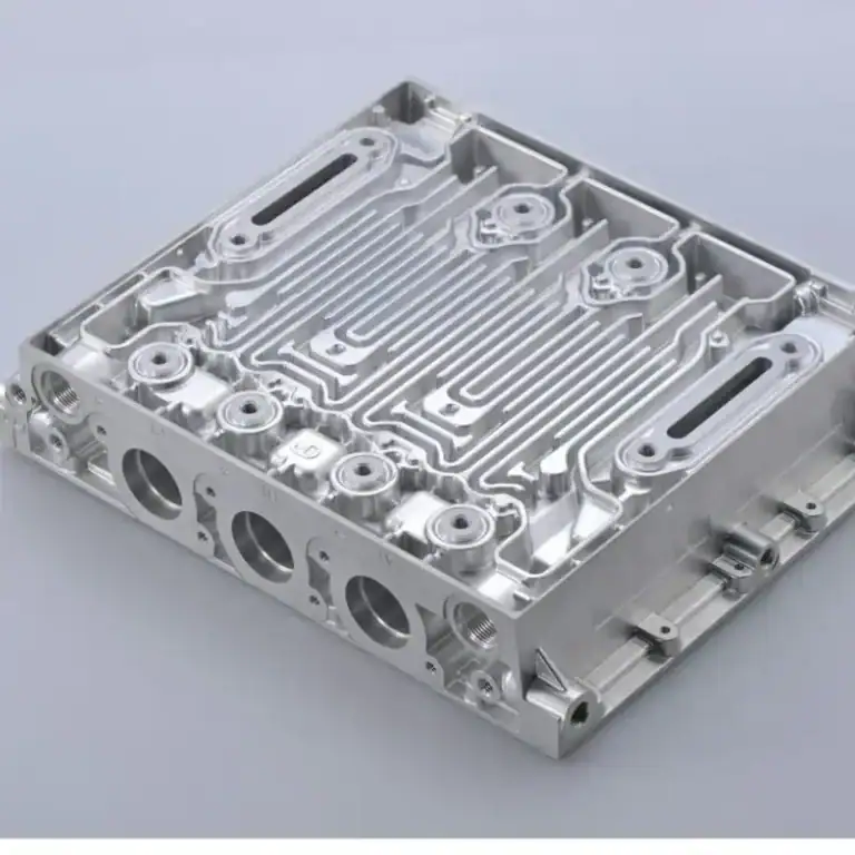
Vacuum chambers are precision enclosures designed to create and maintain controlled low-pressure environments for semiconductor manufacturing, research equipment, coating systems, testing platforms, and other vacuum-dependent processes. Their performance depends on more than simply removing air. Chamber geometry, sealing surfaces, material stability, internal cleanliness, port accuracy, and leak integrity all affect how reliably the system can reach and maintain its target vacuum level.
This guide explains how vacuum chamber machining moves from material selection and DFM through rough machining, multi-axis CNC processing, flatness control, sealing-surface finishing, internal-feature machining, cleaning, leak testing, and inspection. It also covers the manufacturing decisions that influence chamber stability, cost, and repeatable production quality.
What Is A Vacuum Chamber And How Does It Work?
A vacuum chamber is a sealed enclosure designed to maintain pressure below the surrounding atmosphere. A vacuum pump removes gas from the chamber, while valves, gauges, flanges, ports, and seals work together to control pressure and prevent unwanted leakage. The chamber body must remain mechanically stable and leak-tight throughout operation.
How Does A Vacuum Chamber Work?
A vacuum chamber begins with a sealed internal volume. A connected vacuum pump removes gas molecules from that volume, lowering the pressure until the required operating condition is reached.
The chamber does not create vacuum by itself. Its role is to maintain a controlled enclosure while pumps remove gas and valves regulate flow. The ability to hold vacuum therefore depends on the complete system, including the chamber walls, sealing interfaces, ports, connections, and pumping hardware. Xometry describes the chamber, pump, valves, and gauges as connected parts of the overall pressure-control system.
What Components Make Up A Vacuum Chamber System?
A typical system may include the chamber body, vacuum pump, valves, pressure gauges, feedthroughs, flanges, seals, gas ports, cooling connections, and internal fixtures.
The exact configuration depends on the application. A semiconductor process chamber may include many interfaces for gas delivery, sensors, electrical connections, wafer handling, and thermal control, while a simpler test chamber may have fewer ports.
For machining, every additional interface creates another relationship that must be controlled relative to the chamber datum system.
How Do Vacuum Pumps, Valves, And Gauges Work Together?
The vacuum pump removes gas from the enclosure. Valves isolate sections of the system, control pumping paths, or regulate process gases. Gauges measure chamber pressure and provide feedback to the equipment controls.
These devices connect through machined ports, flanges, threaded interfaces, or welded structures.
If those interfaces are poorly aligned, scratched, contaminated, or dimensionally incorrect, the surrounding hardware may be installed correctly while the chamber still fails to hold stable vacuum.
Why Does Chamber Construction Affect Vacuum Performance?
The chamber must resist atmospheric pressure without excessive deformation while keeping all joints and seals stable.
Material selection, wall thickness, weld quality, flange geometry, and sealing-surface condition therefore influence final performance. Innovent emphasizes that vacuum-chamber effectiveness depends on material selection, precision machining, joints, seals, and post-fabrication surface treatment rather than on enclosure shape alone.
Poor construction can also create trapped volumes, contamination sites, or surfaces that are difficult to clean.
What Materials Are Used For Vacuum Chambers?
Vacuum chamber materials must provide sufficient structural strength, dimensional stability, corrosion resistance, machinability, and vacuum compatibility. Aluminum and stainless steel are the most common choices, while carbon steel and specialty materials are used when magnetic, thermal, chemical, or application-specific requirements justify them.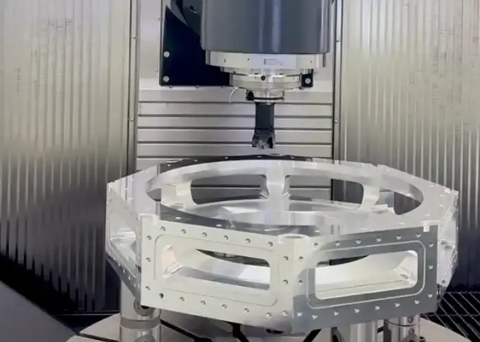
6061 And 6061-T651 Aluminum
6061 aluminum is widely used for CNC vacuum chamber bodies, lids, doors, adapter plates, and structural components because it combines low density, good machinability, useful strength, and thermal conductivity.
For large machined chambers, 6061-T651 plate can offer improved dimensional stability because the material has been stress relieved.
However, stress-relieved material can still move when large internal pockets are machined. Runsom’s large aluminum vacuum-chamber-door case illustrates how residual stress, machining sequence, clamping, and thermal effects can influence final flatness after the part is released.
304 And 316L Stainless Steel
Stainless steel is common where corrosion resistance, chemical compatibility, structural strength, or vacuum cleanliness are important.
304 is widely used for general vacuum hardware, while 316L may be selected where improved corrosion resistance or process compatibility is required.
Compared with aluminum, stainless steel produces higher cutting loads and more heat. Large chamber components therefore require careful tool selection, coolant control, and machining strategy.
Carbon Steel And Specialty Materials
Carbon steel can be used for selected vacuum chambers where cost, stiffness, magnetic properties, or equipment-specific requirements favor it.
Innovent and Keller both note that carbon steel may be used in specialized chamber applications, sometimes with nickel plating to provide the required surface or magnetic characteristics.
Other materials may be selected for extreme temperature, corrosion, magnetic, or research requirements.
How To Select Materials For Vacuum And Process Conditions
Material selection should begin with operating pressure, chemical exposure, temperature, chamber size, cleanliness requirements, mechanical loading, and surface treatment.
The easiest material to machine is not automatically the best chamber material.
For example, aluminum may reduce weight and machining time, while stainless steel may provide better chemical resistance. The engineering decision should consider the entire service environment and manufacturing route.
How Should A Vacuum Chamber Be Designed For CNC Machining?
A machinable vacuum chamber design should establish clear functional datums, maintain sufficient structural stiffness, provide practical tool access, and make sealing surfaces, ports, and internal features easy to inspect and clean. Good DFM reduces manufacturing risk without weakening the chamber’s vacuum function.
Define Functional Datums And Critical Interfaces
The datum system should reflect how the chamber actually installs and aligns in the final equipment.
A main mounting surface may establish the position of ports, internal fixtures, doors, or mating modules. If machining and inspection use unrelated references, tolerance stack-up can become larger than necessary.
Critical interfaces should therefore be identified before programming begins.
Optimize Wall Thickness And Pocket Depth
Vacuum chambers often contain large internal cavities, which means much of the original billet may be removed.
Very thin walls can move during machining, while deep pockets require long cutting tools with reduced rigidity.
A practical design avoids unnecessarily deep cavities and extremely thin walls unless the functional requirement justifies them. Wall transitions should also reduce abrupt stiffness changes that can contribute to distortion.
Plan Ports, Feedthroughs, And Internal Features
Ports may support vacuum pumps, valves, sensors, electrical feedthroughs, gas connections, cooling lines, or inspection hardware.
Their size and direction should consider cutter access and workholding.
When ports intersect internal cavities, the design should also consider burr removal and cleaning. A feature that can be drilled successfully may still create manufacturing problems if the intersection cannot be inspected.
Design O-Ring Grooves And Sealing Interfaces
O-ring grooves need suitable width, depth, edge condition, and sealing-surface geometry.
The design should also provide enough material around the groove to maintain stiffness during clamping and assembly.
Where metal seals are used, flange geometry and mating surfaces may have different requirements from elastomer-sealed interfaces.
Seal specifications should therefore be linked to the actual sealing method rather than copied from an unrelated chamber.
Avoid Trapped Volumes And Difficult-To-Clean Features
Blind holes, enclosed thread spaces, narrow cavities, and poorly vented pockets can trap gas or cleaning fluids.
In vacuum equipment, these trapped volumes can slowly release gas and behave like apparent leaks even when the chamber wall is physically sealed.
Designing vent paths and accessible internal geometry helps both vacuum performance and post-machining cleaning.
What Is The Vacuum Chamber Machining Process?
Vacuum chamber machining normally progresses from material inspection and roughing to stress stabilization, multi-axis feature machining, port production, and final finishing of sealing and datum surfaces. The sequence should remove large amounts of stock without sacrificing final flatness or positional accuracy.
Raw Material Inspection And Blank Preparation
Production begins by confirming alloy, temper, stock dimensions, and machining allowance.
Large billets or plates should provide enough stock to establish stable reference surfaces before critical features are produced.
Material certificates may also be required when chamber traceability is part of the project specification.
Rough Machining And Balanced Material Removal
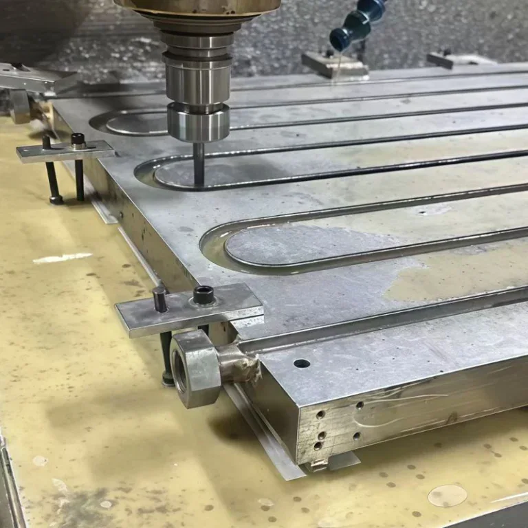
Rough machining removes most of the material from the chamber cavity, external profile, and noncritical features.
For a large aluminum vacuum chamber, removing all stock from one side at once can create unbalanced stress release.
A more stable approach removes material gradually and, where geometry allows, distributes machining more evenly around the part.
Stress Stabilization Between Machining Stages
After heavy roughing, the chamber may need to be unclamped and allowed to stabilize before final machining.
This gives stress-related movement an opportunity to occur while finishing allowance still remains.
For demanding large components, intermediate measurement can identify whether the chamber has shifted enough to require compensation before finishing.
3-Axis, 4-Axis, And 5-Axis Machining
Three-axis machining is efficient for large cavities, flat interfaces, and straightforward chamber geometry.
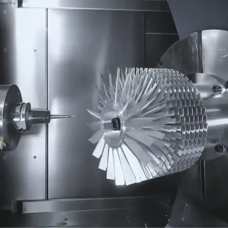
Four-axis and five-axis machining become useful when the part contains features on multiple sides, angled ports, compound interfaces, or difficult tool access.
Reducing repeated manual setups can improve the positional relationship between ports and reference surfaces while reducing datum-transfer error.
Port, Thread, And Interface Machining
Ports, tapped holes, bores, counterbores, flange interfaces, and feedthrough openings are machined after the main chamber geometry is established.
These features should remain correctly positioned relative to the primary chamber datums.
Threaded connections require careful burr control because loose material can later contaminate the vacuum system.
Final Machining Of Critical Surfaces
Critical sealing faces, datum surfaces, locating features, and precision interfaces should generally receive their final cuts after major material removal is complete.
Light finishing passes reduce cutting forces and help preserve geometry.
Once these surfaces are finished, they should be protected during remaining operations, inspection, cleaning, and transport.
How Are Flatness And Dimensional Stability Controlled?
Flatness control begins with material selection and machining strategy, not with the final finishing pass. Large aluminum chambers can move because of residual stress, asymmetric material removal, fixture forces, thin-wall flexibility, and temperature change. Stable results require controlling these factors throughout production.
Residual Stress In Large Aluminum Chambers
Residual stress exists inside aluminum plate before machining begins.
When the outer and inner regions are removed unevenly, the stress distribution changes and the remaining structure can bend or twist.
Runsom’s example of a large aluminum vacuum chamber door highlights this practical problem: a surface can appear flat while clamped and then spring out of tolerance when released.
Symmetrical Roughing And Balanced Stock Removal
Balanced stock removal reduces the chance of releasing most of the internal stress from only one area.
Where part geometry permits, roughing should progress in stages rather than immediately finishing one surface while the opposite side remains untouched.
Uniform finishing allowance also improves the predictability of later precision passes.
Low-Stress Workholding And Support
A fixture should locate the chamber securely without forcing it into an artificial shape.
If a distorted plate is clamped flat during machining, the cutting tool may reproduce that temporary condition. When the clamps are released, the part can return toward its original shape.
Support points, clamp locations, and tightening force therefore affect the final result.
Thin Walls, Deep Cavities, And Tool Deflection
As the internal cavity becomes deeper, the remaining chamber walls become less rigid.
Cutting forces can push thin sections away from the tool, while long-reach cutters may deflect in deep areas.
Finishing passes should use appropriate engagement and tool length. Where possible, structural material should remain in place until late in the machining process.
Temperature Control And Final Stabilization
Aluminum responds noticeably to temperature changes, particularly on large dimensions.
A chamber measured while still warm from machining may give a different result after reaching the inspection-room temperature.
Critical measurements should therefore be taken under controlled conditions after the component has stabilized.
How Are Vacuum Chamber Sealing Features Machined?
Vacuum sealing surfaces must combine correct geometry with controlled surface condition. Flatness, parallelism, groove dimensions, flange geometry, and surface roughness all influence how evenly a seal contacts the chamber. A surface can meet its dimensional location and still leak if it is damaged or poorly finished.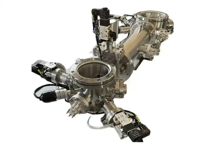
Flatness And Parallelism Of Sealing Faces
A chamber door or flange must contact its seal consistently around the complete perimeter.
If one section is higher or lower, seal compression can become uneven. Runsom’s case study links large-part flatness directly with uniform O-ring contact and chamber sealing behavior.
Parallelism is also important where opposite faces control assembly alignment or compression.
O-Ring Groove Machining
O-ring groove width, depth, corner geometry, and surface finish affect seal compression.
A groove that is too shallow can over-compress the O-ring, while excessive depth may reduce compression.
Burrs or scratches inside the groove can create leakage paths or damage the seal during assembly.
Flange And Metal Seal Interfaces
Metal-sealed flanges require precise interface geometry and careful handling.
Innovent notes the use of both elastomer O-rings and knife-edge metal-seal systems depending on the required vacuum level.
The appropriate machining requirement depends on the flange design, so the supplier should follow the drawing and sealing specification rather than applying a generic finish.
Surface Roughness And Tool Mark Control
Surface roughness describes microscopic texture, while flatness describes overall geometry.
Both may matter on a sealing interface, but they solve different problems.
Final machining should avoid chatter, deep tool marks, and abrupt steps across the contact region. At the same time, specifying an unnecessarily fine finish increases cycle time without automatically improving sealing.
Protecting Sealing Surfaces After Machining
Finished sealing surfaces remain vulnerable after machining.
Deburring, cleaning, inspection fixtures, lifting equipment, and packaging can all introduce scratches.
Protective covers, soft-contact fixtures, and controlled handling should remain part of the production plan until the chamber reaches the customer.
How Are Internal Features And Ports Controlled?
Internal passages and ports must be machined accurately, deburred completely, and left accessible enough for cleaning and inspection. Deep holes and intersecting features are especially important because hidden burrs, chips, or residue can remain inside a chamber even when all external surfaces appear acceptable.
Deep Hole And Internal Passage Machining
Long ports or passages may require deep-hole drilling, extended tooling, or machining from several directions.
The process must control drill wandering, chip evacuation, and tool wear.
Coolant delivery and pecking strategy can help, but the correct process depends on hole diameter, depth, material, and required positional accuracy.
Cross-Hole Burr Control
When two holes intersect, the drill often creates a burr at the internal breakthrough point.
These burrs can be difficult to see and may later detach.
Where internal cleanliness matters, cross-hole intersections should be included in the deburring and inspection plan rather than treated as ordinary drilled features.
Thread And Port Accuracy
Threaded vacuum interfaces must assemble repeatedly without damage or loose particles.
The surrounding port face may also serve as a sealing surface, so the thread axis and face geometry may need to be controlled together.
Gauging alone should not replace inspection of the complete functional interface.
Internal Cleaning Accessibility
An internal passage must be accessible not only to the cutting tool but also to the cleaning process.
Long blind channels can trap coolant, chips, or detergent.
Designing flush paths or removable plugs may improve cleanability when the process allows.
Preventing Trapped Chips And Residue
Machining chips can lodge behind thread roots, inside blind holes, or at channel intersections.
Cleaning should therefore use methods matched to the geometry rather than simply washing the external surfaces.
Visual inspection, borescopes, flushing, or other project-specific verification may be needed for inaccessible areas.
How Are Vacuum Chambers Finished And Cleaned?
Finishing and cleaning prepare the machined chamber for its actual vacuum environment. Surface treatment may improve corrosion resistance or cleanliness, while precision cleaning removes oils, particles, fingerprints, and machining residue that could otherwise contribute to contamination or outgassing.
Machined Surface Finish Requirements
Not every chamber surface needs the same finish.
Critical sealing areas require controlled surface quality, while general external surfaces may only need standard machined condition.
Separating functional and nonfunctional requirements prevents unnecessary finishing work.
Anodizing For Aluminum Vacuum Chambers
Aluminum vacuum chambers may use anodizing where corrosion resistance, electrical behavior, wear resistance, or equipment requirements call for it.
Because anodizing changes the surface, coating allowance must be considered around precision bores, grooves, threads, and mating features.
Masking may be necessary where specific surfaces must remain untreated.
Passivation And Electropolishing For Stainless Steel
Stainless steel chambers may use passivation or electropolishing depending on the application.
Innovent notes electropolishing and chemical passivation as treatments used to improve cleanliness and corrosion behavior in vacuum chamber manufacturing.
Electropolishing can smooth microscopic surface peaks, while passivation helps restore corrosion resistance after fabrication or machining.
Precision Cleaning And Residue Removal
Cleaning should remove cutting fluids, abrasive residue, loose particles, fingerprints, and other contamination.
Internal cavities, threads, channels, and ports require particular attention.
For high-vacuum or semiconductor applications, the cleaning process should follow the customer’s required cleanliness specification rather than rely only on visual appearance.
Clean Handling And Protective Packaging
A cleaned chamber can be contaminated again during final handling.
Critical ports may require covers or caps, while sealing surfaces may need protective material that does not leave residue.
Packaging should prevent dust, impact damage, and direct contact with precision interfaces.
How Are Vacuum Chambers Leak Tested And Inspected?
Vacuum chamber inspection should verify geometry, surface condition, cleanliness, and leak integrity. CMM measurements can confirm dimensional accuracy, but only functional leak testing can show whether the assembled or sealed chamber contains an unintended gas path. Inspection methods should therefore match the actual vacuum requirement.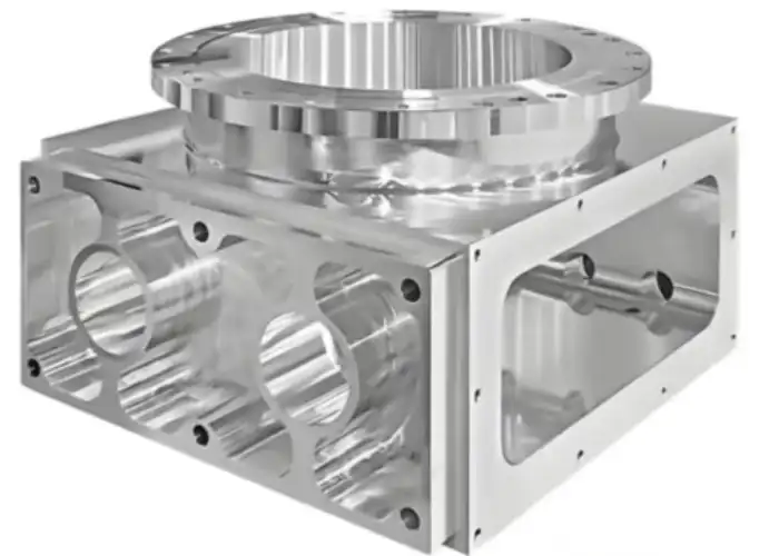
CMM And Dimensional Inspection
CMM inspection can verify port locations, mounting patterns, datum relationships, chamber geometry, grooves, and multi-sided features.
The measurement setup should use the same functional datums defined on the drawing.
Consistent datum strategy is particularly important for chambers with ports machined from several directions.
Flatness And Geometric Inspection
Flatness can be measured using CMMs, indicators, optical methods, or other suitable equipment.
Support conditions should be controlled because a large chamber door or thin panel may deform under its own weight or measurement fixture.
Final acceptance should reflect the part’s required installed or free-state condition.
Surface Roughness And Seal Inspection
Surface roughness should be measured where specified rather than assumed from the machining process.
Visual inspection should also check for scratches, dents, burrs, coating defects, and handling damage.
This is especially important because a localized defect on a sealing surface may cause a problem even when the average roughness is within specification.
Helium Leak Testing
Helium leak testing is widely used for vacuum components because helium can reveal small leak paths that may not be visible.
The correct test setup and acceptance limit depend on the chamber specification and target vacuum level.
A universal leak-rate requirement should not be applied to every chamber without considering the actual application.
Outgassing And Vacuum Performance Verification
A chamber can be physically leak-tight and still struggle to reach the required vacuum because gases or moisture remain on internal surfaces.
Innovent highlights bakeout as a method used in demanding vacuum environments to drive off moisture, hydrocarbons, and trapped gases before service.
Whether bakeout or other vacuum-performance verification is required should come from the equipment specification.
Quality Records And Traceability
Vacuum chamber projects may require dimensional reports, material certificates, surface-treatment records, cleaning documentation, and leak-test results.
These records are especially important for repeat production because they connect the delivered chamber with a specific drawing revision, material batch, and manufacturing process.
Good traceability also makes future troubleshooting more efficient.
How Do Vacuum Chamber Requirements Affect Cost And Lead Time?
Vacuum chamber manufacturing cost is driven by material, chamber size, material removal, machining complexity, tolerance, sealing requirements, surface treatment, cleaning, and leak testing. The most effective cost control comes from specifying tight requirements only where they protect vacuum performance, assembly, and equipment function.
Material And Chamber Size
Large aluminum billets and thick stainless-steel plates can represent a major portion of chamber cost.
Large dimensions also determine which machines, fixtures, lifting equipment, and inspection systems can be used.
Material availability may influence lead time before machining even begins.
Material Removal And Machining Time
A billet-machined vacuum chamber may remove most of its starting material to create a large internal cavity.
High material removal increases machine time and generates more opportunities for distortion.
Design changes that reduce unnecessary stock removal can improve both cost and dimensional stability.
Flatness And Tolerance Requirements
Tight flatness and positional tolerances often require additional machining stages, stabilization time, re-fixturing, and inspection.
The drawing should distinguish true functional requirements from general geometry.
Runsom’s large-part case demonstrates how demanding flatness on a wide aluminum sealing surface can become a process-control issue rather than a simple finishing operation.
Port And Internal Feature Complexity
A chamber with many angled ports, cross holes, feedthroughs, and internal passages requires more programming, tool changes, setups, and deburring.
Five-axis machining may reduce setups, but the complexity of the geometry still influences cycle time.
Features that are difficult to inspect or clean can add further cost after machining.
Surface Treatment, Cleaning, And Leak Testing
Anodizing, passivation, electropolishing, masking, precision cleaning, packaging, and helium leak testing all add manufacturing stages.
These operations should be identified during quotation because they may also change the machining allowance and final inspection sequence.
Adding them after machining can increase both lead time and rework risk.
FAQs
What Is The Best Material For A CNC Vacuum Chamber?
There is no single best material. Aluminum is often selected for lightweight machined chambers because it is easier to machine and has good thermal conductivity. Stainless steel is commonly used where chemical resistance, strength, or vacuum-clean surface requirements are more important. The correct material depends on pressure level, chamber size, temperature, process chemistry, and surface-treatment requirements.
How Can Large Aluminum Vacuum Chambers Maintain Tight Flatness?
Large aluminum chambers require stable material, balanced stock removal, low-stress workholding, staged roughing and finishing, and temperature-controlled inspection. Critical sealing surfaces should generally be finished after most heavy material removal is complete. Final measurements should also be taken after the chamber has been released from clamping forces and allowed to stabilize.
Does Every Vacuum Chamber Require Helium Leak Testing?
No. Helium leak testing depends on the required vacuum level, chamber design, sealing method, and customer specification. High-vacuum, ultra-high-vacuum, welded, or critical process chambers are more likely to require formal leak testing, while some lower-vacuum systems may use different verification methods. The drawing or equipment specification should define the acceptance requirement.
Why Are Vacuum Chamber Sealing Surfaces So Important?
Sealing surfaces determine how consistently an O-ring, gasket, or metal seal contacts the chamber. Poor flatness, scratches, burrs, or unsuitable surface texture can prevent uniform sealing and create leak paths. These surfaces should therefore receive dedicated machining, inspection, handling, and protection throughout production.
Conclusion
Reliable vacuum chamber machining depends on controlling the entire manufacturing chain rather than focusing on one final dimension. Material stability, DFM, roughing strategy, multi-axis machining, flatness, sealing surfaces, internal passages, surface treatment, cleaning, inspection, and leak testing all contribute to the final chamber performance. A well-planned process reduces distortion and contamination while keeping critical interfaces repeatable from prototype through production.
At TiRapid, we provide precision CNC machining and manufacturing services for complex vacuum and semiconductor equipment components, including large aluminum chambers, housings, manifolds, plates, flanges, and multi-sided precision parts. Our 3-axis, 4-axis, and 5-axis machining capabilities support DFM review, complex geometry, dimensional control, and repeat production, while finishing, cleaning, and inspection requirements can be coordinated according to each project’s specifications.