An intake manifold connects an engine’s air supply to its intake ports. Its internal passages, mounting interfaces, and connections must work with the engine as a complete system.
A standard manifold may not suit every project. An engine conversion can change the available space, a different cylinder head can require a new flange, and a modified intake system may need revised sensor or throttle body connections. In these cases, a custom intake manifold can be designed around the actual configuration.
This guide explains the main parts of an intake manifold, the decisions involved in a custom design, and the manufacturing options available. It also examines where CNC machining fits into the process and what to include when requesting a project evaluation.
What Is A Custom Intake Manifold?
A custom intake manifold is an engine intake component designed or modified to meet the fitment, connection, and operating requirements of a specific project. It distributes the incoming charge to the engine’s intake ports through a configuration suited to that engine.
What Does An Intake Manifold Do?
The intake manifold forms part of the path between the incoming air supply and the engine cylinders. Its passages direct the charge toward the intake ports as the engine operates.
What travels through the manifold depends on the fuel system. In many direct-injection and port-injection engines, the manifold primarily carries air. In a carbureted or throttle-body-injection system, it can carry an air and fuel mixture.
The manifold must also interface with other parts of the engine. Depending on the design, these may include the throttle body, cylinder head, injectors, sensors, and vacuum connections.
What Makes An Intake Manifold Custom?
A custom manifold is developed around requirements that a standard part does not fully satisfy. The project may involve a different engine and cylinder head combination, restricted engine bay space, or a throttle body mounted in an unusual position.
Customization can range from modifying an existing manifold to designing a new assembly. Examples include adding an auxiliary port, changing a flange, revising the inlet position, or producing a new plenum and runner arrangement.
The scope should be defined early. A drawing for a machined adapter plate represents a different manufacturing project from a complete manifold with internal passages, joined sections, and testing requirements.
Custom Intake Manifold Vs. Standard Manifold
A standard manifold is designed for a defined engine configuration and may offer a practical solution when the required interfaces and packaging are already available.
A custom design provides more flexibility to address a specific layout or operating goal. That flexibility also brings additional decisions involving design, tooling, manufacturing, and verification.
Custom does not automatically mean better engine performance. The result depends on how well the complete intake system matches the engine, control strategy, and intended use.
What Are The Main Parts Of An Intake Manifold?
Common intake manifold features include an inlet, plenum, runners, and mounting interfaces. The exact layout varies with the engine, fuel system, and available space.
Plenum And Inlet
The inlet connects the manifold to the upstream air supply. In many systems, this connection is located at or near the throttle body.
A plenum is a shared internal volume that supplies the runners. Its shape and position influence how the incoming flow reaches each runner. The design also affects packaging, access, and the location of auxiliary connections.
Not every intake system uses the same plenum arrangement. A custom project should define the required inlet position and surrounding components before the enclosure is finalized.
Intake Runners And Cylinder Head Ports
Runners connect the plenum or inlet arrangement to the intake ports in the cylinder head. Their geometry includes length, cross section, curvature, and the transition at each end.
These features can influence airflow and pressure-wave behavior over the engine’s operating range. They should be considered together with the cylinder head, valve timing, engine speed, and the rest of the intake system.
The runner outlet must also align with the intended cylinder head port. A mismatch can create an unwanted step or interference at the joint, so the port geometry and flange location should be clearly defined.
Flanges, Mounting Holes, And Auxiliary Ports
The cylinder head flange provides the connection between the manifold and the engine. A throttle body flange or other inlet interface connects the manifold to the upstream intake equipment.
Mounting holes, threads, and locating features determine how the assembly is secured. The design may also include connections for a manifold pressure sensor, intake air temperature sensor, vacuum hose, or other engine-specific equipment.
A port that looks simple in a model still needs sufficient material around it, tool access, and space for the fitting or sensor after assembly.
What Should You Consider When Designing A Custom Intake Manifold?
A custom intake manifold should be designed around the engine configuration, intended operating range, available space, and required interfaces. Airflow goals must be balanced with manufacturability, sealing, and service access.
Engine Configuration And Operating Goals
Begin with the engine and cylinder head details. The designer needs to know the number and arrangement of cylinders, the intake port geometry, and whether the engine is naturally aspirated or uses forced induction.
The intended operating range also matters. A road vehicle, an industrial engine, and a competition application may place different emphasis on packaging, drivability, maintenance, or performance over a particular speed range.
The manifold is only one part of the system. Cylinder head design, camshaft timing, throttle body, exhaust, fuel delivery, and engine control can all affect the final result.
Runner Geometry And Plenum Design
Runner length and cross section influence how air moves through the intake system. Pressure waves generated by valve events can also interact with the runner geometry and engine speed.
A longer or shorter runner is not universally superior. The appropriate design depends on the target operating range and the rest of the engine configuration. Plenum size and shape should also be evaluated as part of the complete system.
For demanding projects, simulation or physical testing may help compare designs. The results should be assessed against the project’s actual goals rather than a general assumption that a larger passage always produces more power.
Fitment And Available Space
A manifold must fit the engine before it can be evaluated in operation. Check the position of the cylinder head ports, bolt pattern, throttle body, fuel system, and surrounding brackets.
The available space may be limited by the hood, firewall, cooling system, wiring, or other engine bay components. Clearance must account for installation and service access as well as the final assembled position.
A three-dimensional model of the surrounding components can help identify interference. Where a model is incomplete, critical dimensions should be verified against the actual engine and installation.
Sensors, Injectors, And Auxiliary Connections
The manifold may need mounting locations for sensors and fittings. Depending on the engine, these can include manifold pressure measurement, air temperature measurement, crankcase ventilation, or vacuum-operated equipment.
Port-injection systems may also require injector provisions and support for fuel rails. The location and orientation must suit the injector, sealing arrangement, electrical connection, and nearby components.
Each connection should be defined by its size, thread or interface, location, and intended function. Adding a port late in the project can affect internal clearance, wall thickness, and manufacturing sequence.
Sealing And Service Access
A manifold must seal at the cylinder head and at any other joined interfaces. The design should identify the gasket or sealing method, the contact surface, and the location of the fasteners.
Fastener access is equally important. A hole that is correctly positioned in the model may still be difficult to use if a runner blocks the bolt or tool.
Consider how the manifold will be installed, removed, cleaned, and inspected. A serviceable design gives the technician access to critical fasteners, sensors, and connections without unnecessary disassembly.
What Materials Are Used For Custom Intake Manifolds?
Custom intake manifold materials are selected according to the manufacturing method, operating environment, weight, strength, and interface requirements. Aluminum is common, while steel, stainless steel, and engineered polymers may be suitable for particular designs.
Aluminum Alloys
Aluminum is used in many intake manifolds because it offers a useful combination of low weight and manufacturability. Depending on the grade and form, it can be cast, machined, formed, or welded.
The material specification should match the manufacturing route. An alloy selected for a machined plate is not automatically interchangeable with one intended for a casting or welded fabrication.
When welding is required, the base material, filler, joint design, and finishing sequence should be reviewed together. Machined sealing faces may need to be finished after joining if distortion affects the required dimensions.
Steel And Stainless Steel
Steel or stainless steel may be considered for selected flanges, tubes, brackets, or fabricated assemblies. The choice depends on the operating conditions, required strength, corrosion exposure, and joining method.
These materials differ from aluminum in weight and machining behavior. A mixed-material assembly also requires attention to the way components are joined and how they respond to temperature changes.
The drawing should identify the intended material grade and finish for each component rather than describing the entire assembly with a single broad material name.
Engineering Plastics And Composite Materials
Some intake manifolds use engineered polymers or composite materials. These materials can support lightweight designs and may be selected for thermal or production-related reasons.
Their suitability depends on the material grade, temperature, pressure, chemical exposure, and required service life. The manufacturing route may involve molding or another process that differs from machining a metal manifold.
For a custom low-volume project, the cost and lead time of dedicated tooling should be considered alongside the potential benefits of the material.
How To Choose The Right Material
Start with the engine environment and the loads the manifold must withstand. Then review the available material forms, joining requirements, production quantity, and desired finish.
A useful specification identifies the material grade, condition, and any required certificates. If the manifold is assembled from several components, each part should have its own material and finishing requirements where necessary.
How Are Custom Intake Manifolds Manufactured?
A custom intake manifold can be machined from billet or plate, fabricated from sheet and tube, or produced as a casting and then machined. The best route depends on the internal geometry, quantity, tooling, and project requirements.

CNC Machining From Billet Or Plate
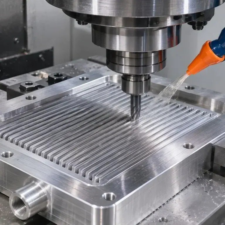
A manifold or its individual sections can be machined from solid material. CNC machining can produce external contours, flanges, ports, holes, and other defined features.
Some designs use multiple machined sections so that internal surfaces can be reached before the assembly is joined. Other geometries may be accessible from available tool directions without dividing the part in the same way.
The main constraint is tool access. A cutter cannot machine an enclosed passage merely because that passage exists in the CAD model. Internal curvature, tool reach, opening size, and assembly method must be considered during design.
Sheet Metal Fabrication And Welding
A fabricated manifold can combine formed sheet, tubes, machined flanges, and other components. The parts are positioned and joined to create the required plenum and runner arrangement.
This approach can provide flexibility for custom layouts. However, the design must account for joint access, alignment, material selection, and changes that may occur during welding.
Critical interfaces may require machining before or after joining, depending on the assembly plan. Cleaning and inspection are also important because the interior must be suitable for use in the engine intake system.
Casting Followed By CNC Machining
Casting can form a manifold body with complex external and internal shapes when a suitable casting process and tooling are available. After casting, CNC machining can finish features that require controlled dimensions or surface contact.
These features may include cylinder head flanges, throttle body interfaces, mounting holes, and threaded ports. The casting design must leave appropriate material for these operations.
Casting tooling and development should be considered when evaluating quantity and project cost. The appropriate choice depends on the part and production plan.
Comparing Manufacturing Methods
| Manufacturing route | Potential advantage | Main consideration |
| CNC machining from billet or plate | Flexible production of machined features and custom sections | Internal tool access, material removal, and joining design |
| Sheet metal fabrication and welding | Flexible arrangement of plenums, tubes, and flanges | Joint design, alignment, weld distortion, and cleaning |
| Casting followed by machining | Suitable for forming a body with complex geometry when tooling is justified | Casting tooling, development, and finish machining requirements |
These routes can be combined. For example, a fabricated manifold may use CNC-machined flanges, while a cast body may need several precision-machined interfaces.
What Is The Role Of CNC Machining In A Custom Intake Manifold?
CNC machining creates and finishes important manifold features such as flanges, sealing faces, ports, holes, and threads. It can be used on individual components or as part of a wider casting or fabrication process.

Machining Flanges And Sealing Faces
Flanges connect the manifold to the cylinder head, throttle body, or another component. Their shape, hole positions, and contact surfaces must match the intended mating parts.
CNC milling can produce flange profiles and finish the contact faces. The drawing should define the critical dimensions and any flatness or surface finish requirements needed for the selected sealing method.
If the flange is welded to other components, the process plan should consider whether the final sealing face needs machining after assembly.
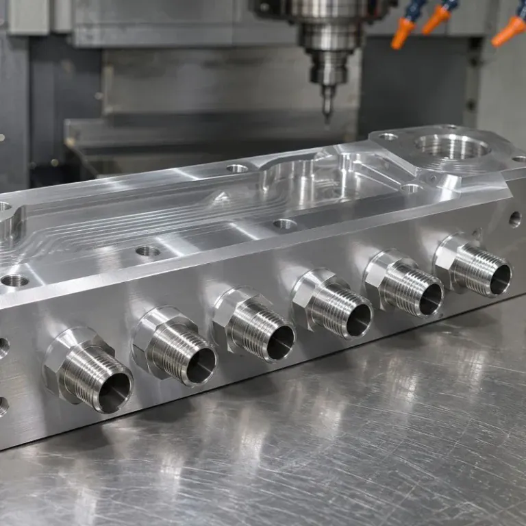
Machining Ports, Holes, And Threads
A manifold may require a combination of large intake openings, mounting holes, threaded fittings, and sensor interfaces.
CNC machining allows these features to be positioned relative to the part’s datums. Their location is important because a correctly sized port can still cause an assembly problem if it is placed at the wrong angle or too close to a neighboring component.
Threads and fittings should be identified by the applicable specification and depth. Where a seal depends on a particular seat or face, that requirement should also be shown.
Machining Runners And Internal Features
Internal runner surfaces can be machined when the tool has sufficient access. Depending on the geometry, the process may involve machining from an open end, working on separate sections, or using another manufacturing route.
Long, curved, or enclosed passages require particular attention. Tool diameter, reach, holder clearance, and the angle of approach all influence what can be produced.
The designer and manufacturer should review the internal geometry together. A split housing or removable section may improve access, but it also introduces a joint that must be sealed and assembled.
When Are Multi-Axis Machines Useful?
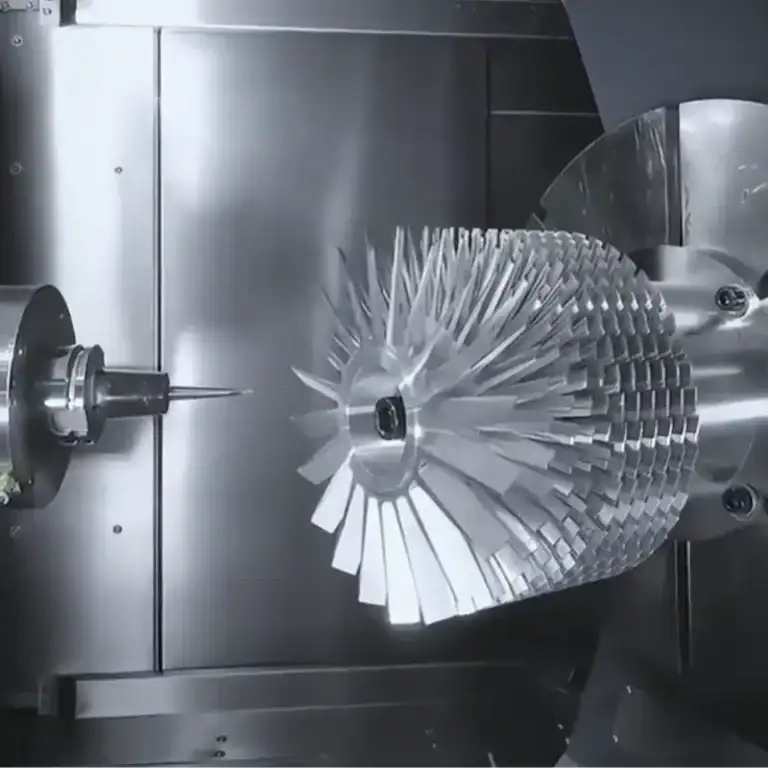
Multi-axis machining can help position a tool for angled ports, complex external contours, or features on several sides of a component.
It may reduce the need for separate orientations in some cases, but the benefit depends on the part, fixture, machine travel, and tooling. A multi-axis machine does not eliminate the physical limits of cutter access inside an enclosed passage.
The machining strategy should therefore be selected after reviewing the complete model, not solely by counting the number of machine axes.
How Is A Custom Intake Manifold Inspected?
Inspection should verify the dimensions, interfaces, surface condition, and testing requirements specified for the manifold. The appropriate checks depend on the design and how the assembly will be used.
Dimensions And Interface Alignment
Dimensional inspection may cover flange outlines, bolt patterns, port locations, threaded holes, and the relationship between mating faces.
A coordinate measuring machine or other suitable measuring equipment can be used where appropriate. The method should match the required tolerance and provide access to the features being checked.
Where possible, the inspection plan should use datums that reflect how the manifold locates on the engine. This helps connect individual measurements to the intended assembly.
Surface Finish And Internal Cleanliness
Sealing faces should be checked against the surface and geometric requirements on the drawing. The required finish depends on the selected gasket or sealing arrangement.
Internal cleanliness is also important. Chips, abrasive residue, weld debris, or loose material left in the intake path can create problems during installation or operation.
The manufacturing plan should include suitable deburring and cleaning, followed by inspection of accessible internal areas.
Leak Testing And Assembly Checks
Leak testing may be specified for joined manifolds or other designs where sealing must be verified. The test method should define the medium, test pressure or vacuum, test duration, and acceptance criteria.
The manifold can also be checked against mating components or a suitable fixture to confirm fit. These checks may identify interference at bolt heads, sensors, throttle bodies, or other connections that is not obvious from an individual dimension.
The specific test conditions should come from the project requirements and be agreed before production.
Flow Testing When Required
Some projects use flow testing to compare runner behavior or evaluate a design against a stated objective. The test setup and conditions need to be defined for the results to be meaningful.
Flow testing does not by itself confirm every aspect of engine performance. Depending on the project, it may be used alongside dimensional inspection, leak testing, simulation, or engine-level evaluation.
What Should You Provide For A Custom Intake Manifold Quote?
A useful inquiry includes the manifold geometry, engine interfaces, material, quantity, and acceptance requirements. Clear information helps the manufacturer evaluate tool access, manufacturing sequence, and inspection needs.

Drawings And Engine Fitment Details
Provide a dimensioned drawing and a three-dimensional model when available. Identify the engine and cylinder head configuration, intake port layout, bolt pattern, and intended throttle body interface.
Include any known space restrictions and the location of nearby components. If the manifold must connect to an existing gasket or mating part, provide the relevant interface information.
The drawing should distinguish between dimensions that are critical to fit and those that can be adjusted during manufacturing review.
Materials, Tolerances, And Finishing
Specify the material grade and condition for the manifold or its individual components. Identify critical tolerances, sealing surfaces, threaded interfaces, and required surface finishes.
If the design includes welded joints or multiple sections, show the intended assembly and any requirements for joint condition or post-assembly machining.
Surface treatments should be identified by type and applicable requirements. The manufacturer can then review their compatibility with the material and the intended engine environment.
Testing, Quantity, And Delivery Requirements
State the required quantity and whether the project is a prototype, a small batch, or an ongoing production order. This information helps determine a practical manufacturing route.
Also identify any required leak test, flow test, inspection report, or material documentation. Test methods and acceptance criteria should be provided where they are already established.
Finally, share the required delivery date and any project milestones. A complete inquiry gives the supplier a better basis for evaluating the work and preparing a quotation.
What If You Only Have A Sample Or Concept?
A sample, sketch, or set of photographs can be useful for an initial discussion. Include as much information as possible about the engine, intended connections, available space, and desired changes.
However, a sample alone may not define the original material, internal geometry, critical tolerances, or acceptance requirements. These details need to be established before a manufacturer can reliably assess the finished part.
If the design is still being developed, identify which dimensions are fixed and which can be discussed during the manufacturing review.
FAQs
Can A Custom Intake Manifold Improve Engine Performance?
It can, when its design is matched to the engine and intended operating range. The result depends on the complete intake system and engine configuration.
How Does A Turbocharged Engine Affect Intake Manifold Design?
The manifold must accommodate boost pressure and operating temperatures. Its structure, joints, and seals should be designed for the expected conditions.
Can An Existing Intake Manifold Be Modified Instead Of Replaced?
Sometimes. Modifications such as adding ports or changing a flange depend on the manifold’s material, condition, and available space.
Conclusion
A custom intake manifold must bring engine fitment, airflow design, materials, and manufacturing requirements together. CNC machining plays an important role in producing flanges, ports, mounting features, and other interfaces, while the complete manufacturing route depends on the manifold’s internal geometry and assembly design.
TiRapid provides CNC machining services for custom components. If your project includes an intake manifold body, flange, adapter, or related machined part, send your drawings, material, tolerances, and quantity for review. Manufacturing and inspection requirements can then be evaluated for your specific design.