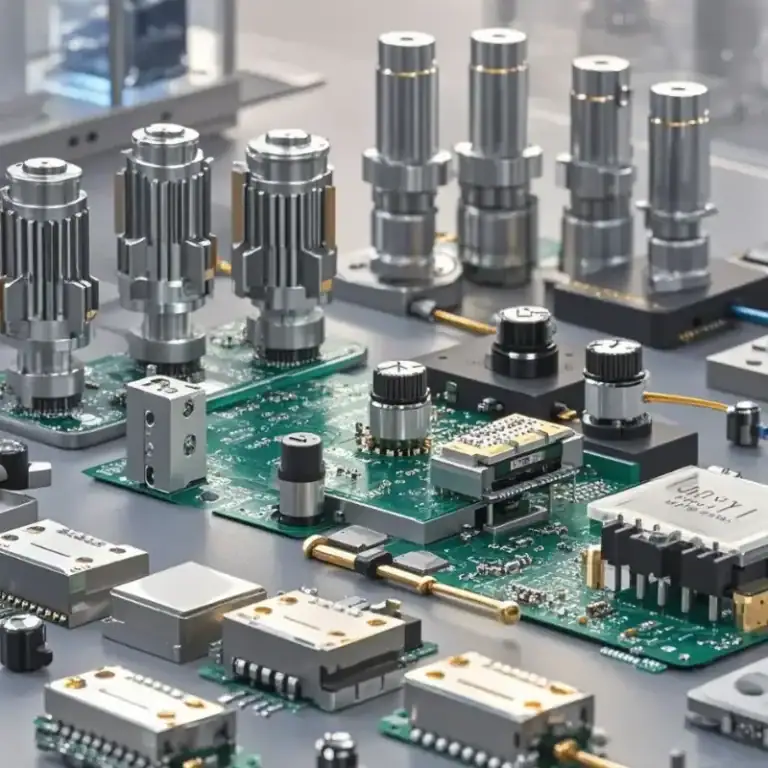
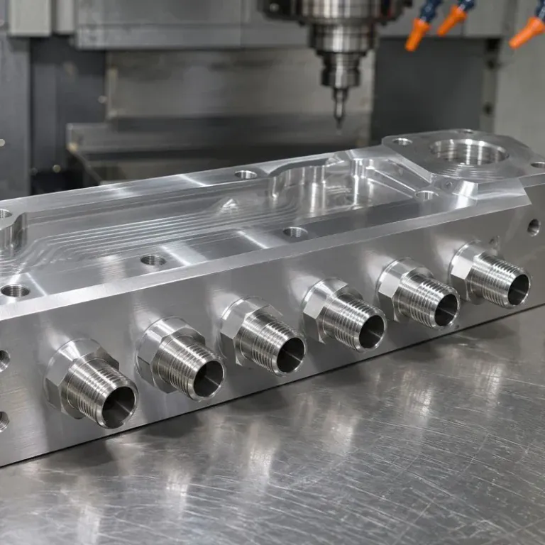
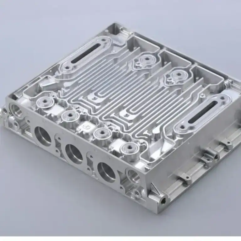
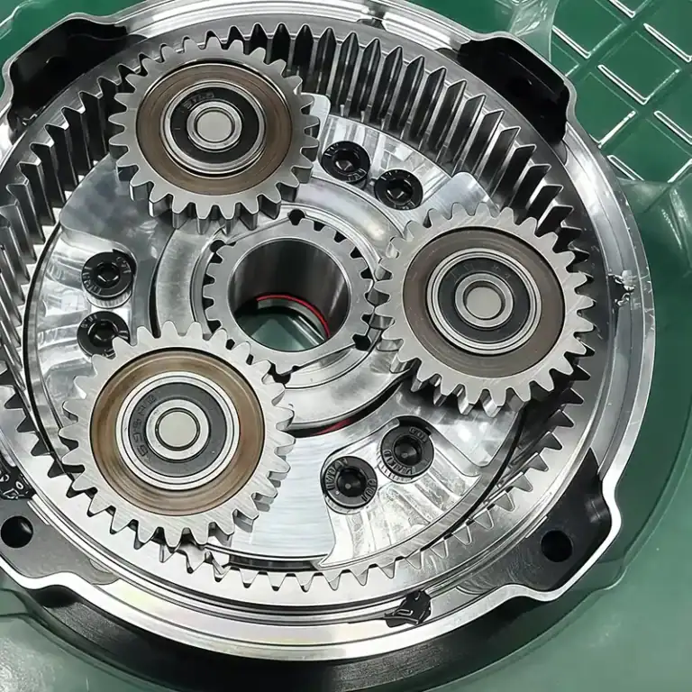
Semiconductor vacuum components are precision parts used to create, maintain, control, and isolate low-pressure environments inside semiconductor manufacturing equipment. Vacuum chambers, flanges, valve bodies, manifolds, chucks, ports, and wafer-handling parts must often combine accurate geometry with reliable sealing, low contamination, and stable performance. In these applications, dimensional accuracy alone is not enough. Surface condition, trapped volumes, burrs, material selection, cleaning, and leakage can all affect equipment reliability.
This guide explains how semiconductor vacuum components are designed and CNC machined, which materials are commonly used, how sealing surfaces and internal channels are controlled, and why cleanliness and leak integrity matter. It also covers machining challenges, surface treatments, inspection methods, and the manufacturing decisions that influence cost and lead time.
What Are Semiconductor Vacuum Components?
Semiconductor vacuum components are mechanical parts that support vacuum generation, gas control, sealing, wafer handling, and process isolation inside semiconductor equipment. They must maintain accurate geometry while preventing unwanted leakage, contamination, and trapped gas from affecting process stability.
Why Is Vacuum Required In Semiconductor Manufacturing?
Vacuum is essential in many semiconductor processes because it creates a controlled environment with reduced gas density and fewer unwanted contaminants. Deposition, plasma etching, ion implantation, wafer transfer, and other process steps rely on low-pressure conditions to control gas behavior and process repeatability. VACGEN identifies deposition, etching, ion implantation, wafer handling, thermal processing, and leak testing as major semiconductor applications of vacuum technology.
Vacuum is also used outside the main process chamber. Atlas Copco notes that house vacuum supports handling, cutting, forming, testing, pick-and-place, and packaging operations across semiconductor manufacturing.
This means semiconductor vacuum systems depend on more than the vacuum pump itself. The performance of the chamber, ports, valves, flanges, chucks, manifolds, and sealing interfaces all contributes to the stability of the complete system.
What Functions Do Vacuum Components Perform?
Vacuum components perform several functions at the same time. A chamber contains the process environment. A flange connects equipment modules. A valve isolates one vacuum zone from another. A manifold controls gas or vacuum distribution, while a chuck holds a wafer or workpiece in a controlled position.
Valve components are especially important in semiconductor equipment because they regulate gas flow, maintain vacuum isolation, reduce cross-contamination, and support controlled gas exhaust. These functions are used across processes including CVD, PVD, plasma etching, ALD, ion implantation, cleaning, and coating.
From a machining perspective, each function creates different requirements. A chamber may prioritize flatness and dimensional stability, while a valve body may require precise bores, seal grooves, and internal flow passages.
How Do Semiconductor Vacuum Systems Work?
A semiconductor vacuum system typically combines a process chamber, semiconductor vacuum pump, valves, piping, sensors, seals, and control hardware.
The pump removes gas from the chamber. Valves regulate or isolate different sections of the system. Flanges, ports, and manifolds connect the components, while seals prevent gas from entering or escaping through the joints.
The machined components must therefore maintain a reliable physical path between these systems. A small scratch on a sealing face, a burr inside an internal passage, or a poorly controlled O-ring groove can create problems even when the overall component dimensions appear correct.
What Semiconductor Vacuum Components Are Commonly Machined?
Common semiconductor vacuum components include vacuum chambers, flanges, valve bodies, manifolds, vacuum chucks, wafer-handling parts, feedthrough housings, and connection hardware. These components vary widely in size and geometry, but most require controlled sealing surfaces, accurate interfaces, and clean internal features.
Semiconductor Vacuum Chambers
A semiconductor vacuum chamber provides the controlled environment required for processes such as deposition, etching, annealing, and cleaning. VACGEN describes process chambers as essential equipment for ALD, CVD, etching, and other semiconductor fabrication processes.
Chambers may contain large pockets, ports, mounting faces, cooling passages, O-ring grooves, and multiple interfaces. Large aluminum chambers can be difficult to machine because extensive material removal may release residual stress and change the final geometry.
The machining strategy should therefore control roughing, re-fixturing, finishing, and final inspection rather than attempting to produce all critical surfaces in one aggressive operation.
Vacuum Flanges And Adapters
Vacuum flanges connect chambers, pumps, valves, gauges, and process lines.
Depending on the design, they may use elastomer seals, metal seals, or other connection systems. The sealing surface, bore, bolt pattern, and interface geometry must remain consistent with the mating component.
CNC turning is efficient for circular flanges, while milling may be required for non-round adapters, multiple ports, or integrated mounting features.
Vacuum Valve Bodies And Valve Components
Vacuum valve bodies combine internal flow paths with sealing surfaces, actuator interfaces, and precision bores.
Common machining features include valve seats, O-ring grooves, guide bores, threaded ports, mounting holes, and internal cavities. Surface condition is particularly important around the valve seat because scratches or burrs may interfere with sealing.
The machining plan should also consider how internal passages will be deburred and cleaned after production.
Gas Manifolds And Distribution Blocks
Manifolds route gases or vacuum through multiple internal passages.
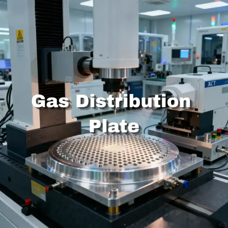
They often contain cross-drilled holes, threaded ports, sealing plugs, pockets, and intersecting channels. These features can be straightforward to machine individually but difficult to clean and inspect once they intersect inside the component.
For semiconductor equipment, the manufacturer should pay close attention to internal burrs, trapped chips, inaccessible corners, and residue from cutting fluids.
Semiconductor Vacuum Chucks
A semiconductor vacuum chuck uses controlled vacuum to hold a wafer or workpiece in position.
The functional surface may contain grooves, holes, channels, or distributed vacuum zones. Flatness and surface condition can directly affect holding consistency and contact.
The back side may also contain ports, mounting holes, and connection features. The top surface and internal vacuum paths should therefore be treated as connected functional features rather than separate machining operations.
Wafer Handling And Transfer Components
Wafer-handling systems use vacuum technology to move wafers while minimizing contact and contamination. VACGEN specifically identifies wafer handling and transfer as an important vacuum application in semiconductor manufacturing.
Machined parts can include end-effectors, support arms, brackets, stages, vacuum pickup components, and mounting hardware.
These components often require a combination of low mass, stable geometry, clean surfaces, and accurate hole locations.
Feedthroughs, Ports, And Connection Components
Feedthrough housings and connection hardware allow electrical, fluid, sensor, or motion interfaces to pass through a vacuum boundary.
These parts may contain precision bores, threads, flange surfaces, O-ring grooves, or welded interfaces.
The main manufacturing requirement is to maintain both assembly accuracy and vacuum integrity around the interface.
What Materials Are Used For Semiconductor Vacuum Components?
Material selection for semiconductor vacuum components depends on vacuum compatibility, corrosion resistance, dimensional stability, mechanical load, thermal behavior, cleanliness, and machinability. Aluminum and stainless steel are common choices, while OFHC copper, titanium, PEEK, and other specialty materials are used when the application requires specific thermal, mechanical, or electrical properties.
6061 And 6061-T651 Aluminum
6061 aluminum is widely used for vacuum chambers, housings, covers, mounting plates, and equipment structures because it machines efficiently and offers a practical balance of strength, thermal conductivity, and weight.
For large precision plates and chambers, 6061-T651 can be useful because the stress-relieved plate condition helps reduce movement during extensive material removal.
However, even stress-relieved aluminum can distort when large pockets or thin walls are machined. Material condition improves stability, but it does not replace a controlled roughing and finishing strategy.
304 And 316L Stainless Steel
304 and 316L stainless steels are commonly used when corrosion resistance, chemical compatibility, or robust vacuum hardware is required.
316L is particularly useful for gas-wetted and vacuum applications where low contamination and surface finishing are important. SinoCMI lists 316L among low-outgassing materials used for semiconductor and vacuum hardware.
Stainless steel is more demanding to machine than aluminum. Heat, work hardening, chip control, and tool wear must be considered carefully, especially for deep holes and internal passages.
OFHC Copper
Oxygen-free high-conductivity copper is selected when thermal or electrical conductivity is important.
Typical applications may include thermal interfaces, electrical components, heat-transfer parts, and specialized vacuum hardware.
Copper machines differently from aluminum or stainless steel because it can be soft and prone to burr formation. Sharp tooling and controlled cutting parameters help maintain edge quality.
Titanium And Specialty Alloys
Titanium may be used where high strength-to-weight ratio, corrosion resistance, or special process compatibility is required.
Other specialty alloys can be selected for thermal expansion, magnetic, sealing, or chemical requirements.
These materials should only be used when their performance benefits justify the higher material and machining cost.
PEEK And Other Engineering Plastics
PEEK and other engineering plastics can be used for insulating components, guides, supports, spacers, and selected vacuum hardware.
The design must consider material creep, thermal expansion, dimensional stability, and compatibility with the operating environment.
Machining parameters should also prevent excessive heat from changing the final geometry.
How To Select Low-Outgassing Materials
Low-outgassing material selection is important because trapped gases, absorbed moisture, lubricants, and incompatible materials can reduce vacuum performance.
The base material, heat treatment, surface condition, cleaning process, and any coatings or adhesives should therefore be considered together.
SinoCMI lists aluminum, 316L stainless steel, titanium, OFHC copper, ceramics, and PEEK among the materials used for semiconductor vacuum components, but final material selection must always follow the actual equipment specification.
How Should Semiconductor Vacuum Components Be Designed For CNC Machining?
Good DFM for semiconductor vacuum components should protect sealing performance, reduce trapped volumes, simplify machining access, and make internal features easier to clean and inspect. The design should define functional datums, critical sealing surfaces, channel geometry, wall thickness, and inspection access before machining begins.
Define Functional Datums And Sealing Interfaces
Datums should reflect how the component locates inside the final system.
A chamber mounting surface, locating bore, flange face, or sealing plane may control the position of several related features.
Using these same functional references during machining and inspection reduces unnecessary tolerance stack-up and makes the quality data more meaningful.
Optimize Wall Thickness And Pocket Depth
Very thin walls and deep pockets reduce component rigidity.
When large amounts of material are removed from an aluminum block, the remaining walls may move after unclamping. Deep pockets also require longer tools, which increases deflection and vibration.
A more manufacturable design uses sufficient wall thickness, reasonable pocket depth, and accessible corner radii without adding unnecessary material.
Design Ports And Internal Channels For Tool Access
Internal passages should be designed with realistic drilling and milling access.
Extremely deep holes, small intersections, and inaccessible cross channels make machining, deburring, and inspection more difficult.
Where possible, channel intersections should be positioned so that the manufacturer can verify that burrs and chips have been removed.
Avoid Trapped Volumes And Virtual Leaks
A virtual leak is not always an actual opening to atmosphere. Gas can remain trapped in blind holes, overlapping threads, cavities, or poorly vented spaces and then slowly release into the vacuum system.
DFM should therefore review blind features, enclosed pockets, and threaded assemblies for unnecessary trapped volumes.
Adding vent paths or changing the geometry may improve vacuum behavior without changing the main function of the component.
Plan Features For Cleaning And Inspection
Machined features should be accessible enough to clean and inspect.
A narrow internal channel may be possible to manufacture but still be difficult to flush or verify. A very deep pocket may also trap machining residue after cleaning.
Designing for post-machining cleaning and inspection reduces the risk of finding problems only after final assembly.
How Are Semiconductor Vacuum Components CNC Machined?
Semiconductor vacuum components are typically produced through a combination of CNC milling, turning, multi-axis machining, deep-hole drilling, port machining, and controlled deburring. The machining sequence should preserve datum relationships, minimize distortion, and leave sealing surfaces and internal passages in a condition suitable for cleaning and inspection.
Precision Milling Of Vacuum Chambers And Housings
Large chambers and housings often begin as aluminum plate, billet, or near-net-shape material.
Rough milling removes the majority of the material while leaving allowance on critical walls and sealing surfaces. The part may then be released from the fixture and allowed to stabilize before finishing.
Final milling establishes the sealing faces, mounting interfaces, pockets, and precision datums.
CNC Turning Of Flanges And Cylindrical Parts
Turning is commonly used for round flanges, sleeves, adapters, valve components, and feedthrough housings.
Concentric bores, sealing surfaces, shoulders, and threads can often be produced efficiently in one controlled setup.
When turned parts later require milling, the machining plan should preserve the relationship between the rotational axis and the milled features.
4-Axis And 5-Axis Machining Of Complex Features
Four-axis and five-axis machining can reduce the number of setups required for complex vacuum parts.
Angled ports, multiple chamber faces, compound holes, and difficult-to-reach interfaces can often be machined more accurately when the part does not need to be manually repositioned repeatedly.
SinoCMI highlights 3-axis, 4-axis, and 5-axis machining for UHV chambers, vacuum housings, process kits, and other semiconductor components.
Deep Hole And Internal Channel Machining
Deep holes and internal channels are common in vacuum manifolds, cooling structures, and distribution components.
The main risks include drill wandering, poor chip evacuation, burrs at intersections, and incomplete cleaning after machining.
Tool length, coolant delivery, drilling sequence, and inspection method should be planned before production begins.
Thread, Port, And Interface Machining
Threads and ports connect vacuum components to valves, fittings, gauges, and process lines.
Thread quality must support repeatable assembly without generating loose material. Port faces may also act as sealing surfaces and therefore require controlled perpendicularity and surface condition.
Critical connection features should be protected during later deburring, cleaning, and surface treatment.
Internal Deburring And Edge Control
Deburring is a functional process for vacuum components, not just an appearance operation.
Cross holes, milled channels, and threaded intersections can retain small burrs that later detach during cleaning or operation.
The process should remove sharp edges and loose material without changing critical sealing geometry or precision interfaces.
How Are Vacuum Sealing Features Machined?
Vacuum sealing depends on geometry and surface condition working together. Flatness, parallelism, groove dimensions, seal contact, and surface roughness must be controlled according to the sealing method, because a dimensionally accurate component can still leak if the mating surface is scratched, warped, or poorly finished.
Flatness And Parallelism Control
Flatness is critical where two surfaces must seal or support an aligned assembly.
Large aluminum components can change shape after machining, so flatness should be checked in the free state rather than only while the part is clamped.
Parallelism is important when opposite faces establish the position or alignment of a vacuum assembly.
O-Ring Groove Machining
O-ring grooves require controlled width, depth, corner geometry, and surface condition.
An incorrect groove may over-compress or under-compress the seal, while burrs or scratches can create leak paths.
The groove should therefore be machined and inspected as a functional sealing feature rather than a general pocket.
Metal Seal And Flange Surface Machining
Metal seals often require more demanding surface control than general elastomer seals.
The exact requirements depend on the flange and sealing system. Manufacturers should follow the drawing instead of applying one generic roughness or flatness value to all vacuum flanges.
Damage during handling is also a major risk because a small scratch may affect an otherwise acceptable surface.
Surface Roughness And Tool Mark Control
Surface roughness influences seal contact and cleaning behavior.
The final toolpath should avoid deep cutter marks, chatter, or steps across critical sealing regions.
However, excessively fine finishes should not be specified without a functional reason because they increase cycle time and inspection cost.
Protecting Sealing Surfaces During Production
A sealing face can be machined correctly and then damaged during later operations.
Fixtures, deburring tools, cleaning baskets, inspection equipment, and packaging can all scratch or dent the surface.
Protective covers, soft contact materials, and clear handling instructions help maintain the final condition.
What Are The Main Challenges In Vacuum Component Machining?
The main machining challenges are distortion, thin-wall movement, deep-cavity tool deflection, internal burrs, multi-datum alignment, and contamination control. These problems are connected, so a stable process must consider material behavior, workholding, tool access, and post-machining cleaning together.
Distortion In Large Vacuum Chambers
Large aluminum chambers can move significantly after heavy material removal.
Balanced roughing, intermediate stress release, low-stress clamping, and final light cuts help improve stability.
For very large parts, inspection should also consider temperature because aluminum dimensions change relatively quickly with temperature variation.
Thin Walls And Deep Cavities
Thin walls are less rigid and may deflect under cutting force.
Deep cavities often require long tools that are more sensitive to vibration. Using smaller radial engagement, appropriate toolpaths, and staged finishing can reduce the risk.
Where possible, temporary support material can be retained until late in the machining sequence.
Long-Reach Tool Deflection
Long-reach tools are sometimes unavoidable in deep vacuum chambers and manifolds.
Deflection can create dimensional error, taper, chatter, and poor surface finish.
Tool diameter, length, holder geometry, spindle speed, feed, and engagement should be optimized around the actual reach requirement.
Burrs In Cross Holes And Internal Channels
Intersecting holes are difficult because burrs often form where the operator cannot easily see them.
If the burr remains inside a gas or vacuum channel, it may later detach and become contamination.
Special deburring tools, borescopes, flushing, and accessible intersection design can improve control.
Datum Control Across Multiple Features
Vacuum components may contain ports, seals, locating holes, and mounting faces on several sides.
Repeated re-clamping can introduce error between these features.
Multi-axis machining and a well-planned datum structure can reduce unnecessary transfers and improve positional consistency.
Preventing Particle And Residue Contamination
Machining oil, chips, polishing residue, and abrasive particles must be removed before the part enters a sensitive vacuum system.
Internal passages are especially difficult because contamination may remain hidden after external surfaces appear clean.
The manufacturing route should therefore connect machining, deburring, cleaning, inspection, and packaging as one process.
How Are Surface Finish And Cleanliness Controlled?
Surface finish and cleanliness are controlled through machining, surface treatment, precision cleaning, handling, and packaging. The objective is not simply to make the component look clean, but to prevent residues, particles, corrosion, or coating defects from affecting vacuum performance or semiconductor process reliability.
Machined Surface Finish Requirements
Different surfaces require different finishes.
A sealing face may need controlled roughness and flatness, while a noncritical external surface may only require standard machining quality.
Applying the same finish everywhere increases cost without necessarily improving performance.
Anodizing For Aluminum Vacuum Components
Aluminum components may be anodized for corrosion protection, wear resistance, electrical behavior, or equipment-specific surface requirements.
Anodizing changes surface dimensions, so precision bores, threads, grooves, and mating surfaces may require masking or machining compensation.
The drawing should clearly state whether final dimensions apply before or after coating.
Passivation And Electropolishing For Stainless Steel
Passivation is used to improve corrosion resistance after machining stainless steel.
Electropolishing can improve surface smoothness and cleanability by removing a controlled amount of surface material.
SinoCMI lists electropolishing and passivation among finishing processes used for semiconductor vacuum parts.
Precision Cleaning And Particle Removal
Cleaning should remove cutting fluid, chips, fingerprints, abrasive residue, and other contamination.
Internal channels, blind holes, and threads require special attention because they can retain fluids or particles after general washing.
If the project specifies a cleanliness limit, the cleaning process should be linked to a defined verification method rather than relying only on visual inspection.
Clean Packaging And Recontamination Prevention
A clean component can become contaminated again during storage or shipping.
Ports may need caps, sealing faces may need protective covers, and parts may need individually sealed packaging depending on the project specification.
Handling after cleaning should minimize direct contact with critical surfaces.
How Are Vacuum Components Leak Tested And Inspected?
Final inspection should verify the features that affect sealing, assembly, cleanliness, and vacuum integrity. Dimensional inspection alone cannot prove that a complex vacuum component is leak-tight, so CMM measurement, surface inspection, cleaning verification, and helium leak testing may all be required depending on the drawing and application.
Common Sources Of Vacuum Leakage
Leaks can originate from damaged sealing surfaces, incorrect O-ring grooves, porous or defective welds, loose fittings, scratches, poorly assembled interfaces, or incomplete sealing.
A machining defect may be very small but still create a continuous path between atmosphere and the vacuum system.
Inspection should therefore focus on both dimensions and functional sealing conditions.
Helium Leak Testing
Helium leak testing is commonly used to detect small leaks in vacuum equipment because helium can pass through very small openings and can be detected sensitively.
SinoCMI lists helium leak testing as part of quality verification for UHV chambers and semiconductor vacuum components.
The acceptable leak rate must come from the customer or equipment specification. There is no single value suitable for every semiconductor vacuum component.
CMM And Dimensional Inspection
CMM inspection is useful for checking port location, hole patterns, datum relationships, groove position, flatness-related geometry, and complex machined features.
Measurement should use the same functional datum scheme defined on the engineering drawing.
For repeat production, consistent inspection methods help compare batches and identify process drift.
Flatness And Geometric Inspection
Flatness, parallelism, perpendicularity, and positional tolerances may affect sealing and assembly.
Large components should be measured under controlled support conditions to avoid forcing them into a temporary shape.
Inspection after unclamping is especially important where machining stress or thin walls may influence final geometry.
Surface Roughness And Seal Inspection
Surface roughness should be measured where the drawing requires it.
Visual inspection should also check sealing surfaces for scratches, dents, burrs, coating defects, and handling damage.
A surface can meet a roughness value while still containing a localized defect that affects sealing.
Cleanliness Verification And Quality Records
Cleanliness verification may include visual checks, particle testing, residue testing, or another customer-defined method.
Material certificates, dimensional reports, leak-test records, surface treatment certificates, and revision records may also be required.
Traceability becomes increasingly important when the same semiconductor vacuum components are produced repeatedly for equipment OEMs.
How Do Manufacturing Requirements Affect Cost And Lead Time?
The cost of semiconductor vacuum components is mainly influenced by material, part size, machining complexity, sealing requirements, tolerance level, surface treatment, cleaning, leak testing, and inspection. Applying tight specifications only where they protect vacuum performance and assembly can reduce cost without reducing functional quality.
Material And Raw Stock Size
Large aluminum blocks, thick stainless-steel plate, titanium, copper, and specialty materials can significantly influence raw material cost.
Large chambers may also generate high material waste because the finished component contains deep cavities or open internal space.
Near-net material forms can reduce machining time in some projects, but they may introduce additional sourcing or inspection requirements.
Chamber Size And Geometry Complexity
Large components require larger CNC machines, stronger fixtures, longer tools, and more handling time.
Multiple angled ports, internal passages, deep pockets, and five-axis features add programming and machining time.
The number of setups is also important because every new setup adds handling, alignment, and inspection requirements.
Tolerance And Sealing Surface Requirements
Tighter flatness, position, parallelism, and surface requirements require more controlled finishing and measurement.
A general structural face does not need the same control as a vacuum sealing face.
Separating critical and noncritical features on the drawing can therefore reduce unnecessary manufacturing work.
Surface Treatment And Precision Cleaning
Anodizing, passivation, electropolishing, coating, masking, cleaning, and special packaging all add production steps.
These processes can also affect final dimensions and therefore need to be included in the original machining plan.
If a part must return to machining after coating, both cost and lead time increase.
Leak Testing And Inspection Requirements
CMM reports, surface roughness measurement, first-article inspection, helium leak testing, cleanliness verification, and material traceability require additional equipment and documentation.
These operations should be defined before quotation so the supplier can build them into the production route instead of adding them after machining is finished.
FAQs
Which Materials Are Best For Semiconductor Vacuum Components?
There is no single best material. 6061 or 6061-T651 aluminum works well for many chambers, housings, and structural components because it is lightweight and machinable. 304 and 316L stainless steel are useful where corrosion resistance and gas compatibility are important. OFHC copper, titanium, PEEK, and specialty materials are selected when thermal, electrical, mechanical, or process requirements justify them.
How Can Large Semiconductor Vacuum Chambers Be Machined Without Excessive Distortion?
The machining process should use stable material, balanced roughing, controlled workholding, sufficient finishing allowance, and final inspection after unclamping. Removing large amounts of material in one stage can release residual stress and change chamber geometry. Large chambers may therefore need multiple roughing and finishing stages before critical sealing faces are completed.
Why Are Internal Burrs A Serious Problem In Vacuum Components?
Internal burrs can obstruct flow, damage seals, trap contamination, or detach during equipment operation. Cross-drilled passages and intersecting channels are particularly difficult because burrs may remain hidden. Design access, suitable cutting tools, controlled deburring, flushing, and inspection should therefore be considered before production begins.
Does Every Semiconductor Vacuum Component Need Helium Leak Testing?
No. Whether helium leak testing is required depends on the component function, vacuum level, system architecture, and customer specification. Simple non-sealing hardware may not require it, while welded chambers, sealed manifolds, and critical vacuum assemblies often need functional leak verification. The acceptance criterion should always come from the project specification.
Conclusion
Reliable semiconductor vacuum components depend on the complete manufacturing chain rather than CNC accuracy alone. Material stability, datum control, internal passages, sealing surfaces, burr removal, surface treatment, cleaning, inspection, and leak integrity all influence how the finished part performs inside semiconductor vacuum systems. Reviewing these requirements early makes it easier to control quality while avoiding unnecessary machining and inspection costs.
At TiRapid, we provide precision CNC machining and manufacturing services for complex semiconductor equipment components, including vacuum chambers, housings, manifolds, flanges, mounting parts, and multi-sided precision components. Our 3-axis, 4-axis, and 5-axis machining capabilities support complex geometries, DFM review, dimensional control, and repeat production, while additional finishing, cleaning, and inspection requirements can be coordinated according to each project.