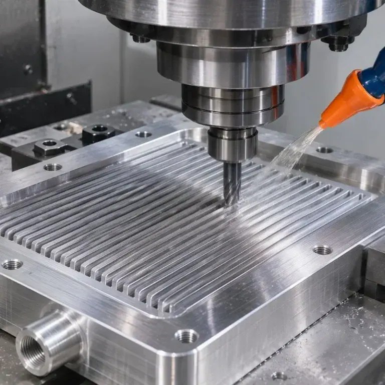
5 axis aerospace machining is used to produce complex aircraft and spacecraft components that are difficult to manufacture with conventional 3-axis equipment. By controlling 3 linear axes and two rotary axes, the cutting tool can reach angled faces, curved surfaces, deep pockets, and multi-sided features while reducing the number of setups required.
This guide explains what 5 axis machining is, when aerospace parts actually need it, which materials and components benefit most, and how the complete manufacturing process works. It also covers titanium and Inconel machining, thin-wall distortion, CAM programming, tolerance control, inspection, cost, and how to evaluate 5 axis machining services for aerospace projects.
What Is 5 Axis Aerospace Machining?
5 axis aerospace machining uses 5 coordinated machine axes to manufacture complex aerospace components with fewer setups and improved access to difficult features. It is especially valuable when a part contains compound angles, curved surfaces, deep cavities, or critical features that must remain referenced to the same datum.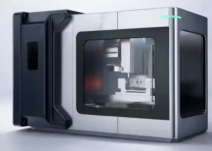
What Is 5 Axis Machining?
5 axis machining combines movement along the X, Y, and Z linear axes with two additional rotary axes. These rotary movements allow either the tool or the workpiece to tilt and rotate during machining.The additional motion changes how the cutter approaches the component. Instead of repeatedly removing and re-fixturing the part, the machine can reach several faces and angled features from one controlled setup.For aerospace parts, this matters because geometry often includes more than simple horizontal and vertical surfaces. Impro notes that 5-axis machining helps produce complex features while maintaining tight geometric relationships and reducing repeated setups.
How Does 5 Axis CNC Machining Work?
In 3+2 machining, the rotary axes move the part into a fixed orientation before a standard 3-axis cutting operation begins. This works well for angled planar faces, drilled holes, and features that do not require continuous rotary movement.Simultaneous 5 axis machining keeps all 5 axes coordinated while the tool is cutting. The tool angle can change continuously as it follows a curved surface, helping maintain access, cutting conditions, and clearance around adjacent geometry.The correct method depends on the geometry. Many aerospace components can be produced efficiently with 3+2 positioning, while turbine blades, impellers, undercuts, and freeform surfaces may require simultaneous motion.
Why Is 5 Axis Machining Important For Aerospace Parts?
Aerospace components are often designed to provide high strength with minimum weight. This leads to pockets, ribs, curved surfaces, angled holes, and compact structures that are difficult to access with a fixed tool orientation.5-axis movement gives engineers more freedom to manufacture these geometries without adding numerous fixtures. Autodesk identifies reduced setup requirements as one of the major reasons 5-axis machining is widely used in aerospace production.Fewer setups can also improve consistency between related features. When holes, bores, mounting pads, and profiles stay referenced to the same setup, there are fewer opportunities for datum-transfer error.
When Is 5 Axis Machining Needed For Aerospace Parts?
Not every aerospace component requires 5 axes. The best candidates are parts with complex surfaces, compound-angle features, difficult tool access, or critical geometry that would otherwise require repeated repositioning and introduce unnecessary tolerance risk.
3 Axis Vs. 3+2 Vs. Simultaneous 5 Axis Machining
3-axis machines are efficient for plates, blocks, simple brackets, and other primarily prismatic components. They become less efficient when the tool must reach several angled faces or continuously curved surfaces.A 3+2 machine indexes the part to a selected orientation and then cuts with 3 linear axes. This reduces setups and works well for multi-face parts with planar features at different angles.Simultaneous 5 -axis motion is more suitable when the cutting angle must change throughout the toolpath. Airfoils, complex impeller blades, and freeform aerospace surfaces are typical examples.
Complex Surfaces, Angled Features, And Undercuts
Complex aerospace geometry can include curved profiles, compound-angle holes, undercuts, and surfaces that cannot be reached from a vertical spindle orientation.Tilting the tool or workpiece improves access while allowing the cutter to remain in a more effective orientation. This can reduce the need for very long tools that are more prone to deflection.Olympus emphasizes that parts with non-orthogonal faces, turbine-style geometry, and difficult access are strong candidates for 5-axis processing because repeated repositioning can increase both cost and accuracy risk.
When Is 3 Axis Or 4 Axis Machining Sufficient?
5-axis machining should not be specified simply because it sounds more advanced. A flat bracket with accessible holes and pockets may be produced more economically on 3-axis equipment.4-axis machining can also handle many rotational or multi-face parts without requiring continuous 5-axis motion. The manufacturing method should follow the actual feature geometry and datum requirements.Using a more complex machine than necessary can increase programming and machine-hour costs without improving the finished part. The best process is the simplest one that reliably satisfies the drawing.
What Aerospace Parts Can Be Machined With 5 Axis CNC?
Aerospace 5-axis CNC machined parts commonly include turbine components, impellers, structural brackets, monolithic frames, engine housings, and titanium hardware. These parts benefit from multi-angle access, reduced setups, and better control of relationships between critical features.
Turbine Blades, Blisks, And Impellers
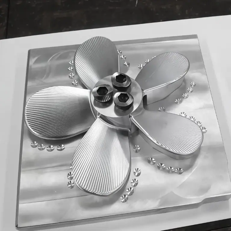
Turbine blades have continuously changing aerodynamic surfaces that require controlled tool orientation throughout the cut. The root, airfoil, and tip must remain accurately related to one another.Blisks and impellers add narrow channels between blades, increasing the risk of tool or holder interference. 5-axis motion allows the tool to tilt away from adjacent geometry while following the required surface.Baker identifies turbine blades and impellers as key simultaneous 5-axis applications because fixed-angle machining cannot continuously maintain the required tool-to-surface relationship.
Aerospace Structural Brackets And Lightweight Frames
Aircraft brackets and structural frames often begin as aluminum or titanium billet and contain large amounts of material removal. Ribs and thin walls remain after deep pockets are machined to reduce weight.These parts may also contain features on several faces that all reference a common mounting datum. Re-fixturing between faces can introduce small positional differences that accumulate across the part.Machining more features in one 5-axis setup helps preserve the original reference system. This is particularly useful for monolithic structures with thin walls and multiple critical interfaces.
Engine Housings And Complex Multi-Sided Components
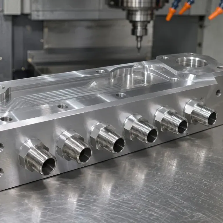
Engine housings and equipment enclosures can combine bores, ports, mounting faces, sealing surfaces, and angled holes on several sides.A 5-axis process can access these features without repeatedly repositioning the housing. This reduces non-cutting time and makes it easier to maintain bore and face relationships.The same logic applies to complex avionics housings and guidance-system enclosures. Their geometry may appear less dramatic than a turbine blade, but positional accuracy between connectors, bores, and sealing faces can still justify 5-axis processing.
Custom Aerospace Titanium 5-Axis CNC Machining Parts
Titanium is widely used where high specific strength, corrosion resistance, and mechanical performance are important. Typical 5-axis titanium parts include structural brackets, mounts, housings, and high-load components.Custom aerospace titanium 5-axis CNC machining is particularly useful when the part combines difficult material with multiple angled surfaces or deep features. Fewer setups reduce the need to repeatedly locate an already expensive workpiece.Because titanium is slower and more demanding to machine than aluminum, process planning must control heat, cutting engagement, workholding, and tool life from roughing through final finishing.
What Materials Are Used In 5 Axis Aerospace Machining?
Common materials include high-strength aluminum alloys, titanium, nickel-based superalloys, stainless steel, and high-strength steels. Each material changes cutting speed, tool choice, heat control, workholding, and the amount of machining time required.
| Material | Typical Advantage | Main Machining Concern | Common Aerospace Use |
| 7075 / 7050 Aluminum | High strength-to-weight ratio | Thin-wall distortion | Structural parts |
| Ti-6Al-4V | Strength and corrosion resistance | Heat and tool wear | Brackets, mounts |
| Inconel 718 | High-temperature strength | Work hardening | Engine components |
| Stainless Steel | Corrosion resistance | Cutting forces and heat | Shafts, housings |
| High-Strength Steel | Load capacity and durability | Tool wear | Landing and structural hardware |
Aerospace Aluminum Alloys
7075 and 7050 aluminum are common in structural aerospace applications because they combine high strength with relatively low density.Aluminum can be machined at high material-removal rates, but lightweight structures may become unstable as large pockets are removed. Thin walls and ribs require balanced cutting strategies.5-axis access can reduce unnecessary re-clamping during this process. This is especially useful when multiple structural features must remain aligned after significant material removal.
Titanium Alloys
Ti-6Al-4V is one of the most familiar aerospace titanium alloys. It provides high strength, corrosion resistance, and useful performance across demanding environments.Titanium does not dissipate cutting heat as effectively as aluminum, which increases temperature near the tool edge. Cutting parameters and coolant delivery must therefore protect tool life and surface integrity.5-axis tool orientation can help maintain stable cutting conditions around complex geometry. However, the process still requires rigid tooling, controlled engagement, and careful monitoring.
Inconel And Nickel-Based Superalloys
Nickel-based superalloys are used when components must retain strength at high temperature. Inconel 718 is a familiar example in engine and propulsion applications.These materials are difficult to machine because they remain strong during cutting and can work-harden. Excessive rubbing or unstable engagement can shorten tool life quickly.5-axis machining does not remove the material challenge, but it can improve access and tool orientation. Stable toolpaths help maintain more consistent engagement through complex features.
Stainless Steel And High-Strength Steels
Stainless steels and precipitation-hardening grades may be used for aerospace shafts, housings, fittings, and load-bearing hardware.Compared with aluminum, these materials generally require lower cutting speeds and greater attention to heat, cutting force, and tool wear. Material condition and heat treatment can also affect final machining strategy.The process route should therefore consider whether critical features will be completed before or after heat treatment. Finishing operations may be needed after thermal processing when dimensional requirements are tight.
What Is The 5 Axis Aerospace Machining Process?
A reliable process begins before cutting starts. DFM, datum planning, raw-material condition, workholding, CAM programming, roughing, finishing, and inspection must be connected so each operation supports the final dimensional and quality requirements.
CAD Review, DFM, And Datum Planning
The process starts by reviewing the 3D model, drawing, tolerances, and surface-finish requirements. Engineers identify critical features, difficult tool access, thin walls, and areas where 5-axis motion is genuinely useful.Datum planning is equally important because the machining setup should reflect how the component will be inspected and assembled. Critical features should remain connected to a practical reference system.Good DFM can also reduce cost before production begins. Increasing an internal radius, improving tool clearance, or removing an unnecessary tolerance may significantly simplify machining without changing function.
Material Preparation And Workholding
Material grade, condition, size, and traceability requirements should be confirmed before machining begins. Aerospace parts may start from billet, plate, forging, casting, or other approved stock.The fixture must hold the workpiece securely while leaving enough access for 5-axis tool motion. Clamps and fixture elements should not block the areas that the tool or spindle needs to reach.For thin-wall parts, excessive clamping pressure can distort the workpiece before cutting even starts. Low-stress support and predictable datum location are therefore essential.
Roughing And Semi-Finishing
Roughing removes most of the excess stock and establishes the overall geometry. The goal is high productivity without introducing excessive heat, vibration, or deformation.Semi-finishing leaves controlled material on critical surfaces before the final pass. This step helps equalize remaining stock and reduces the load placed on the finishing tool.For lightweight aerospace parts, roughing sequence can strongly affect stability. Balanced material removal reduces the chance that one side of the part moves before final dimensions are produced.
5 Axis CAM Programming And Toolpath Optimization
5-axis CAM programming controls not only cutter position but also tool orientation. The programmer must manage reach, holder clearance, machine limits, and potential collisions throughout the toolpath.Tool orientation can be optimized to use shorter cutters and more effective cutting areas. This improves rigidity and can reduce chatter in deep or angled features.Impro notes that programming complexity increases significantly with additional axes, making capable CAM software and experienced process planning important to cost-effective production.
Precision Finishing And In-Process Measurement
Finishing operations establish final surfaces, profiles, bores, and critical feature relationships. Cutting forces are normally lower than during roughing so geometry can be controlled more precisely.Machine probing can be used to confirm setup location, feature position, or workpiece movement before final cutting. Tool measurement can also detect wear or length changes that would affect finished dimensions.In-process measurement does not replace final inspection, but it helps prevent errors from continuing through the complete machining cycle. This is particularly valuable on expensive aerospace workpieces.
What Are The Main Challenges In 5 Axis Aerospace Machining?
The largest challenges come from difficult materials, lightweight geometry, restricted tool access, and complex machine motion. Thin walls may distort, titanium generates concentrated heat, Inconel work-hardens, and long-reach tools can deflect or collide with nearby geometry.
Thin-Wall Distortion And Residual Stress
Thin walls are common because aerospace structures are designed to reduce weight. Unfortunately, the same geometry that saves mass also reduces machining rigidity.As material is removed, internal stresses in the billet can redistribute and cause the part to move. Cutting forces and clamping pressure may add further temporary distortion.Machining strategies should leave stable support during roughing and delay sensitive finishing until most stock is removed. Final dimensions should be verified after fixture forces are released where appropriate.
Deep Cavities And Difficult Tool Access
Deep pockets are frequently used in lightweight brackets and structural components. These features can require long tools when machined with conventional fixed-axis approaches.5-axis motion can tilt the cutter and improve access, often allowing shorter tooling. Shorter tools generally provide better rigidity and reduce deflection.Chip evacuation must still be considered, especially in deep cavities. Recutting trapped chips can damage the surface, increase heat, and shorten tool life.
Heat Generation And Tool Wear In Titanium
Titanium machining concentrates heat near the cutting edge, making thermal control one of the main process concerns.Excessive heat increases wear and can reduce dimensional consistency. Coolant delivery, cutting speed, feed, and radial engagement must therefore be selected carefully.5-axis movement can improve cutter access and engagement, but it cannot compensate for poor cutting parameters. Material-specific process knowledge remains essential.
Work Hardening And Cutting Challenges In Inconel
Inconel retains high strength under conditions that would soften many other metals. This makes cutting forces and tool wear significantly higher.If the tool rubs instead of cutting efficiently, the surface can work-harden and become even more difficult to machine. Consistent engagement is therefore important.Process engineers normally prioritize stability and predictable tool life rather than maximum cutting speed. This helps protect both the workpiece and expensive tooling.
Tool Deflection, Chatter, And Collision Prevention
Complex 5-axis motion creates more opportunities for interference between the cutter, holder, spindle, fixture, and workpiece.Tool deflection can also affect profile accuracy when the cutter is long or heavily loaded. Chatter may leave visible marks or alter local dimensions.CAM simulation, suitable tool length, rigid holders, and verified machine kinematics help control these risks. Toolpath verification is therefore a critical part of 5-axis production.
How Are Tolerances And Surface Finish Controlled?
5-axis accuracy depends on machine condition, datum strategy, workholding, tool selection, thermal stability, and inspection. The main advantage is often not a magically tighter machine tolerance, but the ability to reduce setups and preserve feature relationships from one common reference.
Datum Accuracy And Setup Reduction
Every time a part is removed and relocated, the next setup must reproduce its position relative to previous features.Small seating differences can become positional error between bores, faces, and mounting features. These errors become more important when several setups are chained together.5-axis machining can keep more operations within one reference structure. Baker highlights setup reduction as a major way to reduce tolerance stack-up on complex aerospace components.
GD&T And Complex Feature Accuracy
Aerospace drawings often control position, profile, perpendicularity, parallelism, and runout rather than relying only on ± dimensions.These controls describe functional relationships between features. A hole may be acceptable in size but still fail if its position is incorrect relative to the primary datum.Machining and inspection should therefore use compatible datum structures. This reduces disagreement between what the machine produces and what the CMM later measures.
Tool Orientation And Surface Finish Control
On complex curves, tool orientation changes which part of the cutter contacts the workpiece.Maintaining an effective contact angle can improve cutting stability and reduce visible cusp marks. It can also help avoid poor cutting conditions near the center of a ball-end tool.5-axis finishing is therefore valuable on aerodynamic surfaces and complex profiles. Baker notes that continuous tool orientation can improve surface quality on geometry such as airfoils.
Thermal Stability And Dimensional Consistency
Machine tools, cutters, workpieces, and coolant all change temperature during machining.For tight-tolerance features, these changes can influence the measured size. Long programs and difficult materials make thermal stability especially important.Finishing strategy should consider warm-up, coolant condition, tool wear, and inspection temperature. Tight dimensions should not depend on an unstable thermal condition.
How Is Quality Inspected In Aerospace 5 Axis Machining?
Inspection should verify dimensions, geometric relationships, surface condition, material identity, and any documentation required by the customer. Complex 5-axis parts often combine in-process probing with final CMM, profile, and surface inspection.
In-Process Probing And Tool Measurement
Machine probes can locate the workpiece, confirm datum position, and check selected features before the component leaves the machine.This can detect setup shifts or part movement early enough to prevent further machining on an incorrect reference. Tool setters can similarly detect tool length and wear.In-process probing is particularly valuable on long, complex programs. It adds another control point between setup and final inspection.
CMM And Geometric Inspection
CMM inspection is well suited to aerospace parts with complex GD&T requirements.It can measure feature location, profile, bore relationships, perpendicularity, and other geometric controls relative to the specified datum system.The inspection plan should follow the functional drawing logic. Measuring from convenient but unrelated surfaces can produce results that do not represent how the part actually assembles.
Surface Roughness And Profile Inspection
Surface roughness matters on aerodynamic surfaces, sealing faces, bearing interfaces, and sliding features.Profilometers can verify roughness where Ra or another surface parameter is specified. Complex profiles may require CMM scanning or optical measurement.Inspection method should match the tolerance and feature type. A high-density scan is useful only when its measurement uncertainty is appropriate for the requirement.
Material Traceability And First Article Inspection
Aerospace customers may require material certificates that connect the finished component to a specific heat or lot.First article inspection may also be required to demonstrate that the production process can manufacture the drawing correctly. AS9102 documentation is commonly specified by certain aerospace customers or programs.These requirements should come from the purchase order or quality specification. They should not be assumed for every aerospace-related prototype or non-flight component.
What Affects 5 Axis Aerospace Machining Cost And Lead Time?
Cost and lead time depend on material, geometry, material-removal volume, machine time, programming, tooling, tolerance, inspection, and production quantity. 5-axis equipment has a higher operating cost, but fewer setups can make it the more economical process for genuinely complex parts.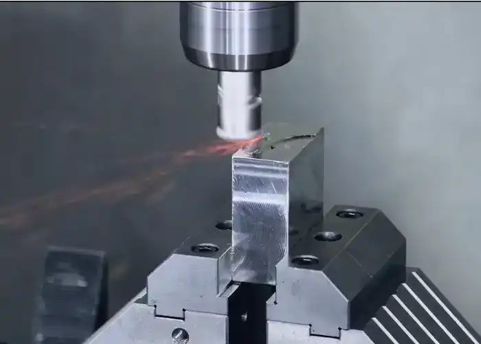
Material Cost And Machining Difficulty
Aluminum generally machines faster than titanium or nickel-based superalloys.Titanium and Inconel require slower cutting conditions and more careful tool management. The difference affects both direct machining time and consumable tooling cost.Raw material form also matters. Machining from a large billet usually requires more time than starting from a near-net forging or casting.
Part Complexity And Material Removal
Aerospace parts can remove a large percentage of the starting billet to create lightweight structures.Deep pockets, ribs, and thin walls increase cutting time even when the finished part itself is relatively small.Design changes that improve tool access or reduce unnecessary pocket depth can lower machining time without affecting the component’s functional performance.
Programming, Setup, And Machine Time
5-axis programming requires more planning than straightforward 3-axis work.Programmers must control rotary motion, tool orientation, collision clearance, workholding, and machine travel limits. Simulation and program verification therefore add engineering time before cutting begins.However, fewer physical setups can reduce fixture design, indicating, handling, and repeated prove-out. This can offset part of the higher machine and programming cost.
Tolerance, Inspection, And Production Volume
Tighter tolerances increase finishing time, tool-control requirements, and inspection effort.Low-volume prototypes may carry more programming and setup cost per part because those engineering costs are spread across fewer units.Repeat production can become more efficient once workholding, CAM programs, tooling, and inspection routines are established and proven.
How To Choose 5 Axis Machining Services For Aerospace Parts?
A qualified supplier should be evaluated by actual machine capability, experience with the required materials, inspection resources, DFM support, and ability to reproduce the process. Simply owning a 5-axis machine does not guarantee reliable aerospace machining.
5 Axis Equipment And Machining Capabilities
The first question is whether the supplier has the correct type of 5-axis capability for the part.Some components need only indexed 3+2 machining, while others require full simultaneous motion. Machine travel, rotary limits, spindle clearance, and work envelope must also match the component size.Autodesk emphasizes defining the required work envelope before selecting aerospace machining equipment. The same logic applies when selecting a machining supplier.
Experience With Aerospace Materials And Complex Parts
A supplier that machines aluminum successfully may not automatically be experienced with titanium or Inconel. Difficult materials require different cutting strategies, tool choices, coolant management, and tool-life controls.Customers should therefore evaluate relevant part and material experience rather than judging capability only by machine brand or axis count.
Quality Control And Inspection Capabilities
Inspection resources should match the geometry and tolerance level of the project.CMM capability, surface measurement, in-process probing, documented inspection methods, and material traceability may all be important depending on the part.For controlled aerospace programs, customers should also confirm any required quality certifications or documentation before ordering. These requirements should be verified directly rather than assumed.
DFM Support And Prototype-To-Production Services
Strong DFM support helps identify machining problems before they become production problems.Engineers can review tool access, wall thickness, internal radii, tolerances, datum structure, and material choice before the final program is released.For prototype-to-production work, maintaining stable fixtures, programs, inspection methods, and process records also makes repeat orders more predictable.
FAQs
What Is The Difference Between 3+2 And Simultaneous 5 Axis Machining?
In 3+2 machining, the two rotary axes position the workpiece at a fixed angle before a normal 3-axis cut begins. The rotary axes remain stationary during the cut.Simultaneous 5-axis machining coordinates all 5 axes while cutting. This is required for many continuously curved surfaces, impellers, turbine blades, and other geometries where the tool orientation must change throughout the toolpath.
Does Every Aerospace Part Need 5 Axis Machining?
No. Simple plates, prismatic brackets, accessible pockets, and many conventional turned parts can be manufactured efficiently with 3-axis or 4-axis equipment.5-axis machining becomes valuable when complex access, continuous curves, multi-face geometry, or tolerance relationships make repeated setups inefficient or risky. Using 5 axes on a simple part may increase cost without improving quality.
Why Is Titanium Difficult To Machine On 5 Axis CNC Equipment?
Titanium produces significant heat at the cutting interface and can accelerate tool wear if engagement is poorly controlled.5-axis movement improves access and allows more favorable tool orientation, but successful titanium machining still depends on rigid tooling, effective coolant, stable cutting parameters, and controlled tool life.
What Should I Look For In 5 Axis Machining Services?
Look for equipment that matches the required part size and motion type, plus demonstrated experience with the material and geometry involved.Inspection capability, DFM support, workholding knowledge, CAM programming, quality documentation, and repeat-production control are equally important. The strongest supplier is not simply the one with the newest 5-axis machine.
Conclusion
5 axis aerospace machining is most valuable when complex geometry, difficult tool access, high-value materials, and tight feature relationships make conventional multi-setup machining inefficient or risky. Successful production depends on selecting the right level of 5-axis motion, controlling workholding and toolpaths, managing material-specific challenges, and connecting machining with GD&T, surface-finish control, and final inspection. Used correctly, 5-axis machining improves access, reduces setup-related variation, and supports reliable production of complex aerospace parts.
At TiRapid, we provide precision CNC machining and manufacturing services for complex aluminum, titanium, stainless steel, engineering plastic, and multi-sided components. Our 3-axis, 4-axis, and 5-axis machining capabilities support DFM, thin-wall structures, deep pockets, complex features, dimensional inspection, and prototype-to-production projects according to each customer’s drawing and quality requirements.