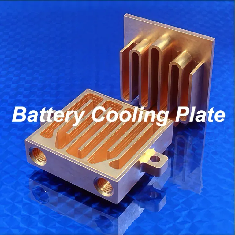
An aluminum water cooling block is a liquid cooling component that transfers heat from electronic devices into circulating coolant. Compared with copper alternatives, aluminum offers lower weight, competitive material costs, and practical CNC machinability. However, cooling performance depends on channel geometry, thermal contact, coolant compatibility, and the complete water cooling system rather than material selection alone.
This guide explains how an aluminum water cooling block works, its main components, types, and material options. It also covers internal channel design, CNC milling, drilling, sealing features, manufacturing challenges, quality inspection, and practical selection criteria.
What Is An Aluminum Water Cooling Block?
An aluminum water cooling block is a compact heat exchanger made partly or entirely from aluminum. It absorbs heat through a metal contact surface and transfers that heat into liquid flowing through internal channels. It is commonly used in electronics, industrial equipment, and custom thermal management systems.
Main Functions Of An Aluminum Water Cooling Block
The main function of an aluminum water cooling block is to remove heat from a component and transfer it into circulating liquid. This allows thermal energy to be transported to a radiator or heat exchanger instead of accumulating near the electronic device.
Water blocks are useful when a heat source has limited space for conventional cooling. CPUs, power electronics, Peltier modules, and industrial control components may benefit from compact liquid-cooled contact surfaces.
The block does not generate cooling by itself. Effective operation requires suitable coolant circulation, external heat rejection, reliable thermal contact, and adequate flow through the internal passages.
Key Components And Basic Structure
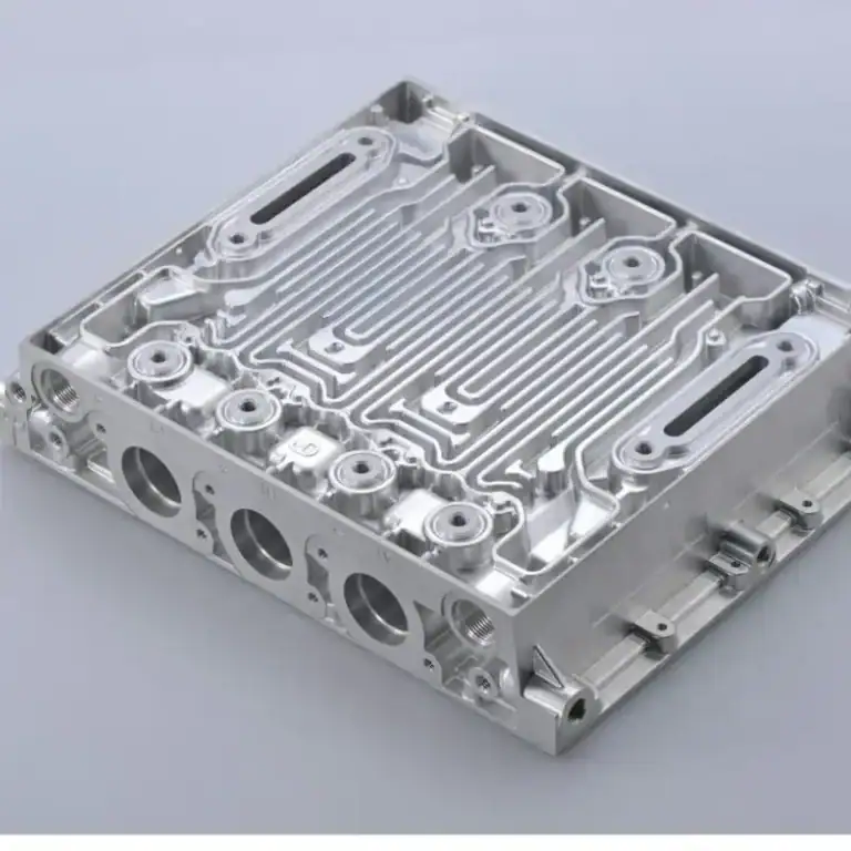
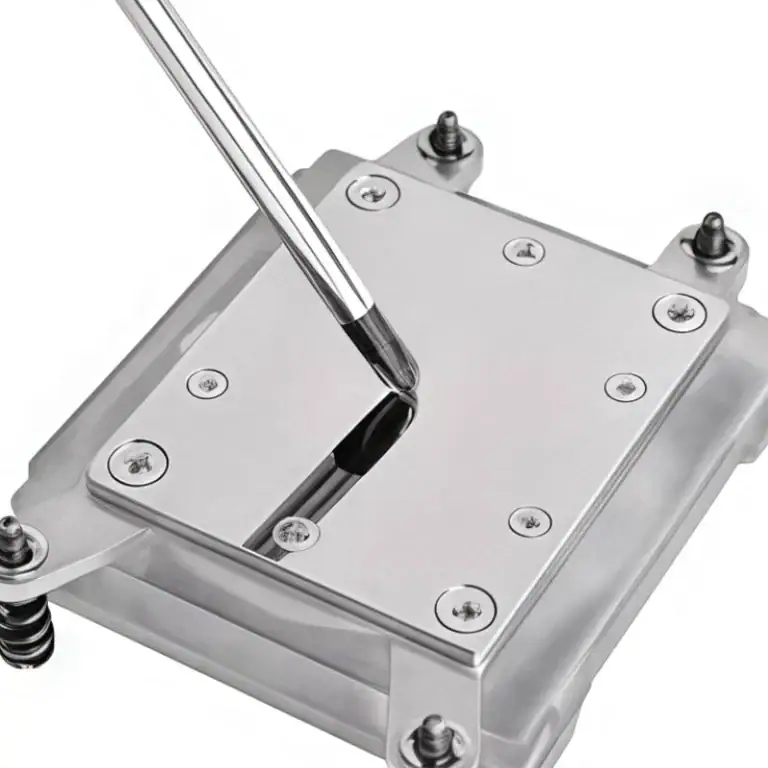
A typical water block contains an aluminum base, internal cooling channels, a sealed cover, inlet and outlet ports, and mounting features. Some designs include microfins, O-ring grooves, or a separate housing made from a compatible material.
The base receives heat from the component, while the channel walls transfer energy to the coolant. A cover encloses the fluid path, and the ports connect the block to the external liquid cooling loop.
| Component | Main Function | Important Manufacturing Requirement |
| Aluminum Base | Conducts heat from the device | Thickness and flatness |
| Cooling Channels | Transfer heat into coolant | Width, depth, and flow path |
| Cover | Encloses the coolant passages | Sealing and structural integrity |
| Inlet And Outlet | Connect the cooling loop | Port location and thread quality |
| Sealing Grooves | Hold gaskets or O-rings | Groove dimensions and surface finish |
| Mounting Features | Secure the component | Hole positions and mechanical fit |
The structure may be simple, but manufacturing accuracy matters. Poor sealing surfaces can cause leakage, while excessive base thickness or uneven contact pressure can increase thermal resistance.
How Does An Aluminum Water Cooling Block Work?
An aluminum water cooling block works through heat conduction and liquid convection. Heat moves from the electronic component into the aluminum base, passes through the channel walls, and is absorbed by circulating coolant. The warmed liquid then flows toward an external heat exchanger.
Heat Transfer From The Contact Surface To Coolant
Heat first passes through a thermal interface between the device and the aluminum block. Thermal paste or another suitable interface material helps fill small air gaps that would otherwise increase contact resistance.
The aluminum base then spreads heat toward its internal channels. As coolant moves along the channel walls, convection transfers energy from the solid metal into the flowing liquid.
Thermal resistance is commonly expressed in °C/W or K/W. For example, an illustrative thermal resistance of 0.10°C/W corresponds to a 20°C temperature difference when transferring 200 W between the specified measurement points. Actual results depend on the complete test conditions.
Coolant Flow Direction And Liquid Cooling Loop Integration
Coolant enters the water block through an inlet port, flows through the internal passages, and exits through an outlet. The channel layout determines how evenly liquid reaches the heated areas.
A complete water cooling system typically includes a pump, radiator or heat exchanger, tubing, fittings, and sometimes a reservoir. The pump circulates coolant, while the external heat exchanger releases the absorbed heat.
Inlet and outlet direction should follow the intended flow path. Some simple blocks allow either direction, but more complex designs may use distribution chambers or jet structures that perform differently when flow is reversed.
What Are The Main Types Of Aluminum Water Cooling Blocks?
The main types of aluminum water cooling blocks include CPU and GPU blocks, Peltier cooling blocks, industrial electronics cold plates, and custom-machined water blocks. They differ in contact geometry, cooling capacity, internal channels, and mounting requirements.

CPU And GPU Water Cooling Blocks
CPU water blocks are designed to transfer heat from a processor package into circulating liquid. Their mounting patterns and contact surfaces must match the processor socket and mechanical installation requirements.
GPU water blocks may cool only the processor core or extend over memory and power-delivery components. Full-cover designs require accurate component positioning and carefully controlled contact surfaces.
Although many high-performance consumer blocks use copper, aluminum designs are available for compatible cooling systems. The material choice must be evaluated against the entire coolant loop, particularly when other components contain copper or brass.
Peltier And Other Electronics Cooling Blocks
Peltier cooling blocks remove heat from the hot side of thermoelectric cooling modules. They are often compact, with mounting surfaces sized to match the module and ports connected to a small liquid cooling circuit.
A thermoelectric module moves heat from its cold side to its hot side while consuming electrical power. Therefore, the water block may need to remove both the transferred heat and the electrical input converted into heat.
Other applications include motor controllers, power semiconductor modules, laser equipment, and industrial electronics. Their heat distribution and mounting requirements often differ from standard computer cooling products.
Standard And Custom Aluminum Water Cooling Blocks
Standard aluminum water blocks are available in common sizes and connection layouts. They are practical when their dimensions, cooling performance, and materials are compatible with the intended application.
Custom blocks provide flexibility in external dimensions, mounting holes, cooling channels, port positions, and contact surfaces. These features help designers fit the block into equipment with unusual packaging constraints.
For prototypes, a simple CNC-machined aluminum block with accessible internal channels may be appropriate. More advanced designs may require additional joining or assembly processes, depending on manufacturing volume and thermal requirements.
What Materials And Coolants Are Used For Aluminum Water Cooling Blocks?
Aluminum water cooling blocks commonly use machinable alloys such as 6061, while some designs use 6063 or other grades. Compatible treated water and inhibited coolant mixtures are frequently used. Material selection must consider conductivity, corrosion, mechanical strength, and machining requirements.
Common Aluminum Alloys For CNC Machining
6061 aluminum is a common choice for custom CNC-machined water blocks because it offers a useful balance of strength, machinability, availability, and corrosion resistance. Its mechanical stability makes it suitable for bases containing ports, threaded holes, and mounting features.
6063 aluminum is frequently associated with extruded thermal products and may also be considered for certain cooling structures. Other alloys require evaluation against structural requirements, stock availability, machining behavior, and the intended coolant environment.
| Aluminum Alloy | Typical Engineering Advantage | Water Block Consideration |
| 6061 | Strength, availability, and CNC machinability | Common option for custom machined blocks |
| 6063 | Good extrudability and thermal applications | Suitable for selected extruded or machined designs |
| 5052 | Good corrosion resistance and formability | More relevant to sheet and fabricated structures |
| 5083 | Higher strength and marine corrosion resistance | Consider for specialized structural requirements |
No single alloy is automatically best for every water cooling block. The choice should account for required heat transfer, wall thickness, thread strength, manufacturing method, and long-term coolant exposure.
Aluminum Vs. Copper Water Cooling Blocks
A copper water cooling block generally offers higher thermal conductivity than an equivalent aluminum design. This can be valuable when heat must travel through a very small contact region or when thermal resistance limits are especially strict.
Aluminum is substantially lighter and may offer lower raw material and machining costs, depending on part geometry and production conditions. For many moderate thermal loads, a well-designed aluminum cooling block can provide adequate performance.
| Property | 6061 Aluminum | Copper |
| Typical Thermal Conductivity | About 167 W/(m·K) | About 385 W/(m·K) |
| Approximate Density | 2.70 g/cm³ | 8.96 g/cm³ |
| Weight For Equal Volume | Lower | Higher |
| Material Cost | Often lower | Often higher |
| CNC Machining | Generally practical | Grade-dependent, burr control important |
| Typical Selection Priority | Weight and cost balance | High thermal conductivity |
These values are representative engineering properties, not guaranteed product specifications. Actual thermal performance also depends on channel geometry, contact resistance, coolant flow, and the completed assembly.
Coolant Compatibility And Galvanic Corrosion
Galvanic corrosion can occur when aluminum and a more noble metal, such as copper, are electrically connected in the presence of a conductive coolant. The aluminum can corrode faster, producing deposits, material loss, or leaks.
This makes mixed-metal cooling circuits an important design risk. An aluminum block should not be added to an ordinary copper-and-brass liquid cooling loop without a properly engineered corrosion-control strategy and verified material compatibility.
Coolant chemistry, inhibitor concentration, temperature, oxygen exposure, and maintenance affect reliability. For aluminum cooling circuits, treated water or a manufacturer-approved inhibited coolant is generally preferable to assuming that untreated water will remain safe over time.
How Do You Design An Aluminum Water Cooling Block?
An aluminum water cooling block is designed by defining the heat load, target temperature, available coolant flow, allowable pressure drop, and mechanical space. Engineers then select the channel geometry, contact thickness, ports, and sealing structure to satisfy these requirements.
Internal Cooling Channel And Microfin Design
Internal channel geometry determines how coolant contacts the heated metal. Straight channels, serpentine passages, parallel grooves, and microfin structures are common options, each with different flow distribution and manufacturing requirements.
Narrower passages can increase the wetted surface area and local heat-transfer coefficient. However, they also increase sensitivity to pressure drop, clogging, burrs, and machining accuracy.
Engineers should optimize channel width, depth, length, spacing, and remaining wall thickness together. Designs that use very thin walls or deep narrow grooves may require revised tool access or a different manufacturing method.
Coolant Flow Rate, Pressure Drop, And Thermal Performance
Coolant flow rate affects how much heat the liquid can transport and how its temperature changes through the block. Higher flow can improve thermal performance, but the improvement is not unlimited.
For example, water flowing at 1 L/min while absorbing 200 W experiences an ideal bulk temperature rise of approximately 2.9°C, assuming steady conditions and water properties near room temperature. This does not represent the device-to-coolant temperature difference.
Pressure drop must be evaluated at the same operating flow. Increasing channel density or reducing passage width can require greater pump pressure, so thermal resistance and hydraulic performance should be reviewed together.
Contact Surface Flatness And Mounting Design
The contact surface must match the geometry of the heat-generating component. Appropriate flatness, surface finish, and mounting pressure help maintain a thin, consistent thermal interface.
Excessive base thickness increases the conduction path, while insufficient thickness can reduce mechanical stiffness or increase distortion. Engineers therefore balance thermal resistance with structural support and machining requirements.
Mounting holes, screw locations, and contact pressure distribution should be defined before machining. Tight tolerances are most valuable at functional interfaces rather than across every external surface of the block.
Port Connections And Sealing Structure Design
Port design determines how the water block connects to tubing or other coolant components. Port position, thread standard, bore diameter, and available installation clearance must match the cooling system.
O-ring grooves and sealing faces require controlled dimensions and surface quality. Poor groove depth, rough sealing surfaces, or misaligned covers can cause leakage even when the internal flow channels are correctly machined.
The design should also consider assembly access and maintenance. Ports that are difficult to reach, unsupported threaded fittings, and seals hidden behind other components can increase installation risk and service costs.
How Are Aluminum Water Cooling Blocks CNC Machined?
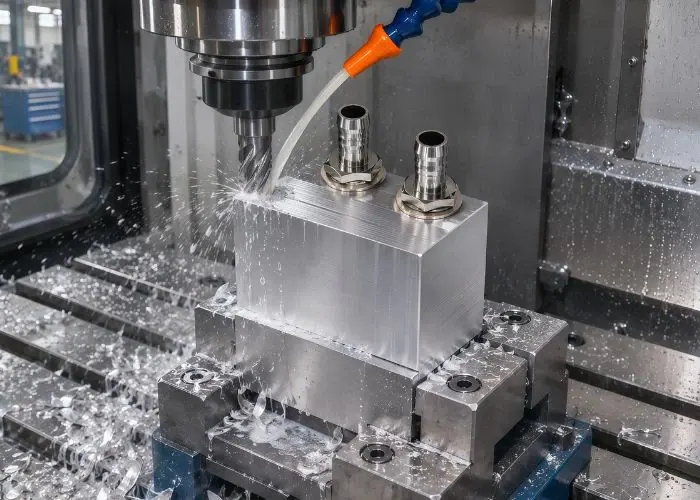
Aluminum water cooling blocks are CNC machined by milling the body and internal flow passages, drilling and tapping connection ports, and producing accurate sealing grooves and mounting features. The process also requires deburring, cleaning, and dimensional inspection.
CNC Milling Of Internal Cooling Channels
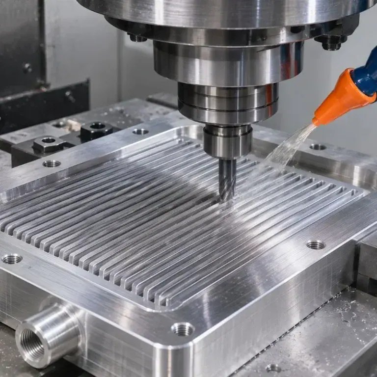
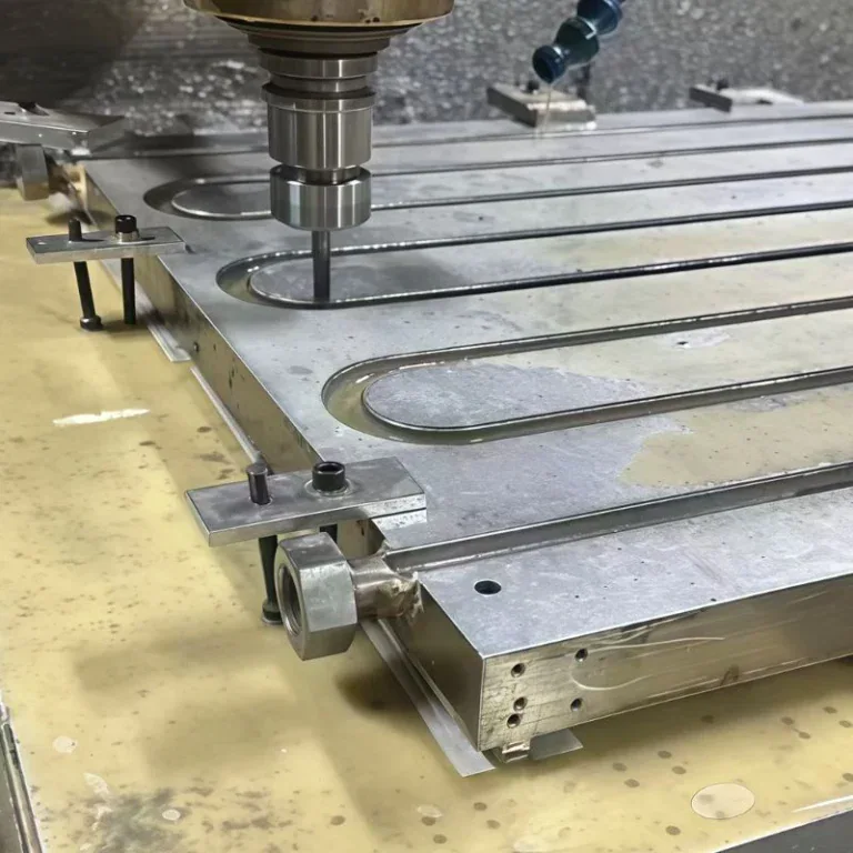
CNC milling creates internal liquid passages using end mills and controlled toolpaths. Common geometries include straight grooves, serpentine channels, pockets, and distribution cavities machined into a solid aluminum block.
Cutting parameters depend on channel width, depth, tool diameter, and part rigidity. Long, narrow channels may require smaller tools and careful chip evacuation to avoid burr formation or damage to thin walls.
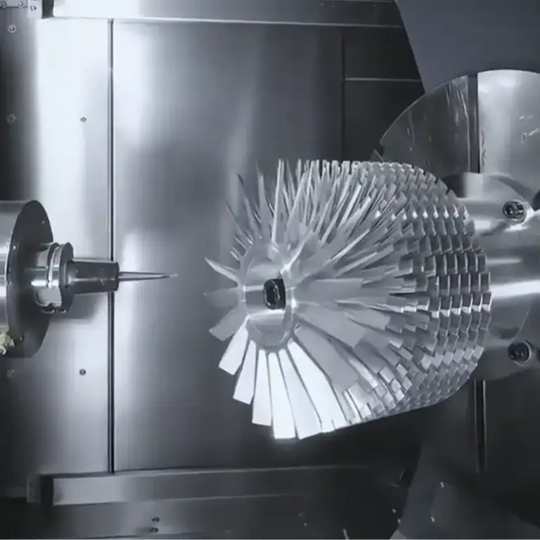
For complex geometries, multi-axis machining can improve access and reduce repeated setups. However, enclosed passages cannot always be produced from one solid piece and may require a separately machined cover or alternative construction.
Precision Drilling, Tapping, And Port Machining
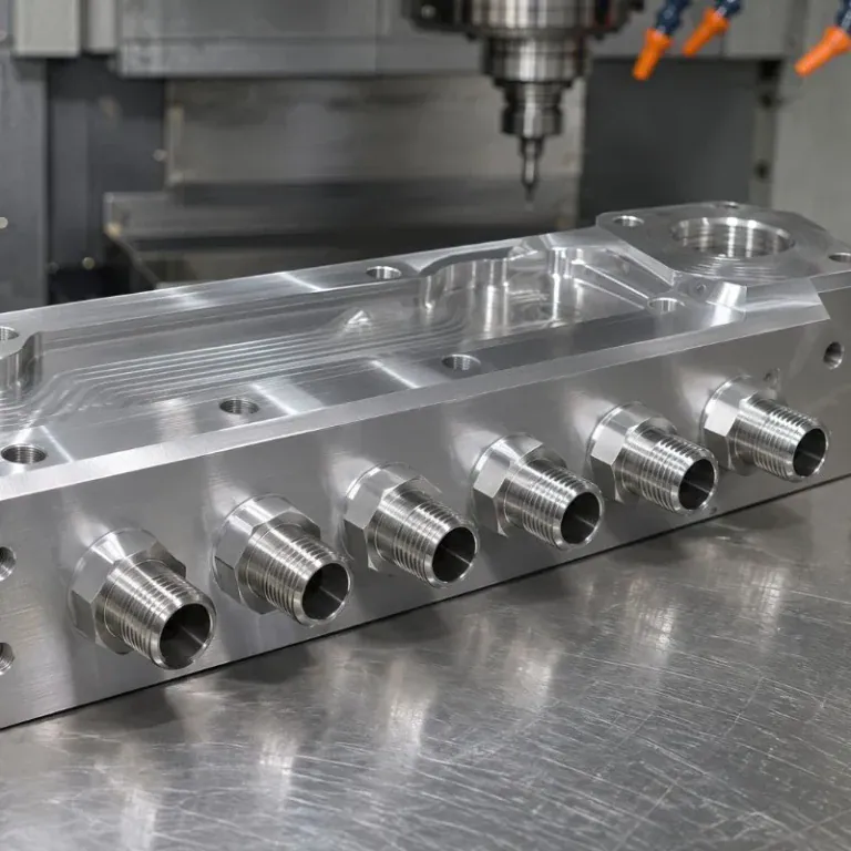
Drilling and tapping create the inlet, outlet, and threaded mounting features needed to connect the water block to the cooling system. Their dimensions must match the selected fittings and engineering drawing.
Thread quality matters because damaged or inaccurate threads can compromise assembly and sealing. Proper tool selection, hole preparation, chip removal, and inspection help improve the reliability of these connections.
For threaded aluminum ports, engineers should also consider available wall thickness and expected assembly loads. Thread inserts or revised connections may be appropriate when repeated servicing or higher mechanical loads are anticipated.
CNC Machining Of Sealing Grooves And Mounting Features
CNC machining produces O-ring grooves, cover seats, mounting holes, and alignment features that support reliable assembly. These details often require tighter geometric control than the external shape of the cooling block.
The sealing groove must match the gasket material, cross-section, compression requirement, and mating surface. A groove that is too shallow or too deep can create excessive compression or inadequate sealing.
Mounting features also influence thermal contact. Hole-position errors, uneven screw loading, or distortion around the contact face can reduce interface quality even when the coolant passages are manufactured accurately.
Surface Finishing, Deburring, And Internal Cleaning
Surface finishing removes unnecessary machining marks from functional areas and helps achieve the specified contact and sealing surface requirements. Different surfaces may require different finishing methods.
Deburring is especially important near intersecting holes, narrow channels, and threaded ports. Loose aluminum particles can circulate through the cooling loop and potentially obstruct smaller passages elsewhere in the system.
After machining, parts should be cleaned using a method compatible with the alloy and any coatings. Cleaning effectiveness is best confirmed before channels are permanently covered and become difficult to inspect.
CNC Machining Challenges And Design For Manufacturability
The main CNC machining challenges include thin-wall deformation, long-tool deflection, burr formation, chip accumulation, and distortion caused by uneven material removal. These risks increase as channel dimensions become smaller or part geometry becomes less rigid.
Design for manufacturability should review cutter accessibility, minimum corner radii, channel depth, setup strategy, stock condition, and inspection requirements. A slightly modified flow path may reduce cycle time without compromising essential thermal performance.
| Design Feature | Common Machining Challenge | Practical Control Method |
| Narrow Cooling Channels | Small tool breakage and burrs | Suitable cutter size and controlled engagement |
| Deep Grooves | Tool deflection and chip buildup | Depth optimization and effective evacuation |
| Thin Walls | Vibration and distortion | Stable fixturing and balanced machining |
| Threaded Ports | Thread damage or misalignment | Correct hole preparation and inspection |
| Sealing Grooves | Inconsistent depth or profile | Precision finishing and dimensional checks |
| Large Contact Faces | Flatness changes after machining | Roughing allowance and controlled finishing |
The objective is not simply to machine an attractive aluminum block. It is to produce a repeatable thermal component whose flow passages, sealing interfaces, and mechanical features meet the approved design.
How Are Aluminum Water Cooling Blocks Tested?
Aluminum water cooling blocks are tested by checking critical dimensions and surface quality, confirming pressure and leakage resistance, and measuring coolant flow and thermal performance. Different tests address different failure modes, so acceptance criteria must be defined for each design.
Dimensional Inspection And Surface Quality
Dimensional inspection verifies channel width, depth, port positions, threads, mounting holes, contact flatness, and sealing groove geometry. These measurements confirm that machining results match the approved drawing.
Depending on feature size, suitable methods may include calipers, micrometers, coordinate measurement, optical inspection, or surface measurement equipment. Small internal passages may require inspection before the cover is installed.
Surface quality inspection also checks for burrs, scratches, embedded chips, and visible damage. Functional contact and sealing surfaces should receive greater inspection attention than noncritical cosmetic areas.
Pressure Testing And Leak Testing
Pressure testing checks whether the assembled cooling block can withstand its specified internal pressure. Leak testing determines whether fluid escapes from ports, seals, covers, or other connections.
Hydrostatic testing and pressure-decay methods may be used depending on product requirements. More sensitive methods can be considered when the application has particularly strict leakage limits.
Test pressure, duration, temperature, medium, and pass criteria must follow the approved engineering specification. A universal test pressure should not be assumed for every aluminum water cooling block.
Coolant Flow And Thermal Performance Testing
Flow testing measures how much coolant passes through the block under a defined pressure difference. It helps identify flow restrictions, blocked passages, or unexpected hydraulic losses.
Thermal performance testing applies a controlled heat load and records the device temperature, coolant temperature, flow rate, and pressure drop. Results can be used to calculate thermal resistance under stated test conditions.
Comparing measurements across several samples helps evaluate manufacturing consistency. Unexpected differences may indicate channel variation, assembly problems, trapped air, or inconsistent thermal contact.
What Are The Advantages And Limitations Of Aluminum Water Cooling Blocks?
Aluminum water cooling blocks offer low weight, practical CNC machinability, and potentially lower manufacturing costs. They can provide effective cooling for many applications, but their limitations include lower thermal conductivity than copper, galvanic corrosion risks, leakage concerns, and system maintenance requirements.
Lightweight Design, Cost, And Cooling Benefits
Aluminum has a density of approximately 2.70 g/cm³, compared with about 8.96 g/cm³ for copper. For an equivalent volume, an aluminum component is therefore substantially lighter.
Its availability and CNC machinability also support custom prototypes and industrial production. A well-designed aluminum water cooled heat sink can be appropriate when the thermal target can be reached without requiring copper’s higher conductivity.
However, lower raw material cost does not always mean lower finished-part cost. Complex channels, high scrap risk, special sealing requirements, or demanding inspection can outweigh the difference in material price.
Aluminum Water Cooling Blocks Vs. Air Heat Sinks
An aluminum water cooling block transfers heat into circulating liquid, while an air heat sink transfers heat to surrounding air through fins and airflow. Each method has different system requirements.
Liquid cooling can move heat away from densely packed electronics and reject it at a remote radiator. Air cooling avoids liquid leakage risks and may be simpler to install and maintain.
| Factor | Aluminum Water Cooling Block | Air Heat Sink |
| Heat Transport | Circulating liquid | Local airflow |
| External Equipment | Pump and heat exchanger | Fan or natural convection |
| Installation | More complex | Usually simpler |
| Leakage Risk | Present | None from coolant |
| Remote Heat Rejection | Possible | Usually more limited |
| Best Fit | Compact or concentrated heat loads | Simpler systems with sufficient airflow |
Neither design is automatically superior. The correct comparison includes the entire cooling system, available space, temperature limits, reliability requirements, and operating cost.
Corrosion, Leakage, And Maintenance Challenges
Corrosion can reduce water block reliability when coolant chemistry, wetted materials, or operating conditions are incompatible. Galvanic corrosion is particularly important when aluminum and copper are combined without proper engineering controls.
Leakage may result from damaged seals, inaccurate grooves, improper assembly, or connection problems. These failures can affect surrounding electronic equipment, making sealing and installation procedures important.
Routine maintenance may involve checking coolant condition, looking for deposits, confirming stable flow, and inspecting connections. The appropriate service interval depends on the coolant supplier and the system’s operating environment.
How Do You Choose The Right Aluminum Water Cooling Block?
The right aluminum water cooling block should match the heat load, mounting geometry, coolant loop, material compatibility, and manufacturing budget. Standard blocks are suitable for common applications, while custom CNC-machined designs provide greater flexibility for specialized components.

Size, Compatibility, And Cooling Requirements
The block dimensions and mounting pattern must match the electronic component and available enclosure space. Contact area, port direction, fitting clearance, and installation access should be confirmed before selecting a design.
The cooling system must provide enough flow to remove the expected heat load while keeping temperatures within the specified limits. Pump performance should be evaluated together with the block’s pressure-drop characteristics.
A common search question is “aluminum water cooling block how to use.” In practice, correct operation requires compatible fittings and coolant, controlled thermal contact, adequate circulation, and a verified leak-free installation before powering sensitive electronics.
Standard Vs. Custom CNC Machined Cooling Blocks
Standard blocks are often the easiest option when dimensions, ports, and cooling capability already match the project. Their availability may reduce development effort and shorten the selection process.
Custom CNC machining becomes valuable when the cooling component needs unusual channel paths, integrated mounting features, nonstandard ports, or a specific contact surface. It is also practical for prototype development and low-volume industrial applications.
A DIY water cooling block can demonstrate a basic concept, but a production design requires better control of sealing, material compatibility, dimensional accuracy, and performance repeatability.
Manufacturing Cost And CNC Machining Supplier Selection
Manufacturing cost depends on raw material, part size, channel complexity, machining time, tooling, surface treatment, and inspection requirements. Assembly and testing may add separate costs depending on the product scope.
When comparing water cooling block price information, engineers should separate the cost of a bare CNC-machined body from the price of a fully assembled and tested liquid cooling component. These are not equivalent deliverables.
A capable CNC supplier should review the drawing for channel accessibility, tolerance feasibility, sealing surface quality, and inspection methods. For more complex products, joining, final assembly, and thermal testing responsibilities must be clearly defined.
FAQs
Can An Aluminum Water Cooling Block Operate Below Room Temperature?
Yes, but only if the circulating coolant is cooled below ambient temperature by an external system. The block itself does not produce refrigeration. For example, in a room at 25°C and 60% relative humidity, the dew point is approximately 17°C. Surfaces below this temperature may collect condensation. Engineers should control coolant temperature, provide insulation where needed, and protect nearby electronics. Below-ambient operation must be treated as a system-level moisture-management problem rather than a simple cold plate material choice.
How Does Thermal Paste Thickness Affect Water Block Performance?
Thermal paste fills microscopic gaps between the cooling block and the electronic component, but excessive thickness can increase thermal resistance. For example, doubling the thickness of an ideal uniform interface layer doubles its conduction resistance when all other factors remain constant. Actual behavior also depends on paste conductivity, surface roughness, mounting pressure, and contact geometry. Engineers should follow the interface material manufacturer’s application guidance rather than assuming that applying more paste will improve cooling.
Can An Aluminum Water Cooling Block Be Repaired After A Leak?
Some leaks can be repaired, but the repair method depends on the failure location. A damaged removable O-ring or external fitting may be replaceable, while a cracked body or failed permanent joint can be difficult to restore reliably. The repaired assembly should undergo the specified pressure and leakage tests before being returned to service. For high-value electronic equipment, replacement is often more appropriate when structural damage cannot be inspected and validated against the original acceptance requirements.
Should Internal Cooling Channels Be Anodized After CNC Machining?
Internal anodizing may be possible for certain aluminum cooling components, but it must be evaluated carefully. Anodizing changes surface chemistry and introduces an oxide layer whose thermal properties differ from the base aluminum. Complex internal channels may also receive uneven treatment depending on process accessibility. Engineers should consider corrosion protection, coating thickness, channel dimensions, and thermal requirements before specifying the process. Anodizing should not be assumed to eliminate all galvanic corrosion risks in a mixed-metal liquid cooling system.
Conclusion
An aluminum water cooling block provides a practical way to transfer heat from electronic components into a circulating liquid cooling system. Its effectiveness depends on aluminum grade, internal channel geometry, coolant flow, pressure drop, contact flatness, and sealing quality. CNC machining supports accurate custom channels, ports, and mounting features, but reliable performance also requires appropriate corrosion control, cleanliness, inspection, and testing. The best design balances thermal requirements with manufacturing feasibility, cost, and long-term reliability.
At TiRapid, we provide precision CNC machining and manufacturing services for custom aluminum cooling components. Our CNC milling, multi-axis machining, DFM support, and dimensional inspection help customers manufacture precise flow channels, sealing surfaces, and mounting features for specialized liquid cooling applications.