Aerospace machining services manufacture precision components for aircraft, spacecraft, propulsion systems, hydraulic equipment, avionics, and other demanding applications. These parts often combine lightweight geometry, tight dimensional relationships, difficult materials, and strict surface requirements, so machining must be planned around both part function and repeatable quality.
This guide explains what aerospace machining services include, which parts and materials are commonly machined, how CNC processes are planned, and where the main manufacturing risks occur. It also covers thin-wall distortion, titanium and Inconel machining, GD&T, inspection, traceability, prototype-to-production scaling, cost, and the key capabilities to review when selecting an aerospace machining company.
What Are Aerospace Machining Services?
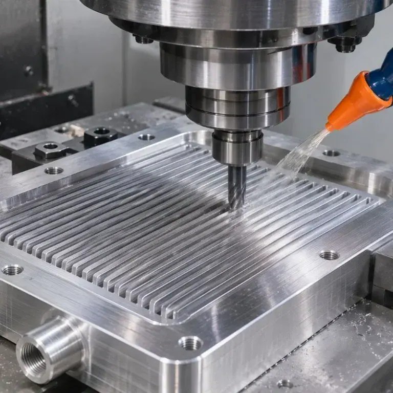
Aerospace machining services combine CNC milling, turning, multi-axis machining, finishing, inspection, and process control to manufacture precision aerospace components. The service is not limited to cutting metal; it also includes material control, datum planning, tolerance management, surface protection, inspection, and production repeatability.
What Does An Aerospace Machining Service Include?
An aerospace machining service normally begins with drawing and CAD review before the first toolpath is programmed. Engineers identify critical dimensions, material requirements, surface finishes, datum structures, difficult features, and any special inspection or documentation requirements.The manufacturing scope may include 3-axis, 4-axis, or 5-axis milling, CNC turning, mill-turn machining, drilling, boring, reaming, grinding, and finishing. The correct combination depends on part geometry rather than automatically using the most complex machine.A capable supplier should also connect machining with inspection and process documentation. JLYPT emphasizes that aerospace CNC manufacturing requires repeatable process planning, robust datum strategies, workholding, probing, metrology, and traceability rather than machine capability alone.
How Is Aerospace Machining Different From General CNC Machining?
Aerospace parts often combine high strength-to-weight requirements with complex geometry. Removing unnecessary mass creates deep pockets, thin walls, ribs, and multi-sided structures that are more sensitive to cutting force and residual stress.The materials are also more demanding. High-strength aluminum, titanium, precipitation-hardening steel, and nickel-based superalloys require different cutting conditions, tooling, cooling, and process controls. Impro highlights 7000-series aluminum, titanium, and Inconel as typical aerospace materials that influence both geometry and machining strategy.Quality evidence is another major difference. Depending on the customer and program, aerospace work may require material certificates, inspection records, first article documentation, revision control, and traceability linking the final component back to its manufacturing history.
What Should Buyers Expect From Precision Machining Service For Aerospace?
Buyers should expect the supplier to understand the drawing as a functional engineering document rather than simply a set of dimensions. Datum structure, GD&T, surface finish, edge requirements, and assembly relationships should influence the machining and inspection plan.A precision machining service for aerospace should also identify manufacturing risks before production. Thin walls, inaccessible corners, long-reach tooling, difficult materials, coating buildup, and unrealistic tolerances are easier to correct during DFM than after machining begins.The final expectation is repeatability. A supplier should be able to reproduce the same process through stable programs, workholding, tooling, measurement methods, and controlled drawing revisions instead of depending on one successful first part.
What Aerospace Parts And Materials Are Commonly Machined?
Aerospace machining services support structural parts, engine hardware, hydraulic components, avionics housings, brackets, fittings, shafts, and other precision hardware. Material selection is driven by strength, weight, temperature, corrosion, and functional requirements, while machinability determines how the manufacturing process must be controlled.
Structural Brackets, Frames, And Fittings
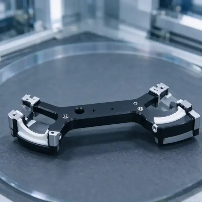
Structural aerospace components include brackets, fittings, ribs, frames, supports, and mounting hardware. These parts often start from billet or plate and use pockets and ribs to remove weight while preserving load paths.Aluminum alloys are widely used because of their strength-to-weight ratio and machining efficiency. Titanium may be selected when higher strength, corrosion resistance, or more demanding load conditions justify the additional machining difficulty.The main manufacturing concern is usually dimensional stability. When large amounts of stock are removed, remaining walls and ribs become less rigid, making balanced roughing, stable workholding, and controlled finishing important.
Engine, Hydraulic, And Avionics Components
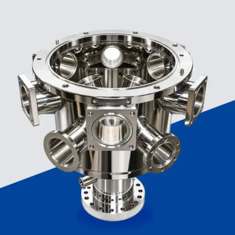
Engine components operate under more demanding thermal and mechanical conditions, so titanium and nickel-based alloys are more common. Complex housings, turbine-related components, and mounts may also require multi-axis access to maintain geometric relationships.Hydraulic parts frequently contain precision bores, threads, sealing faces, and internal passages. Turning, milling, drilling, boring, and reaming may be combined to keep these features accurately related.Avionics housings are often aluminum and may contain thin walls, connector openings, heat-management features, and controlled mounting surfaces. The geometry can appear simpler than engine hardware, but flatness and feature position remain important for reliable assembly.
Aerospace Aluminum, Titanium, Inconel, And Steels
The most common aerospace materials each create a different machining problem. Aluminum supports high removal rates, titanium concentrates heat near the cutting edge, and Inconel combines high strength with severe tool wear and work-hardening risk.Precipitation-hardening stainless steels provide strength and corrosion resistance for fittings, mechanisms, shafts, and similar components. Their material condition and heat-treatment sequence can influence when critical dimensions should be finished.A practical material comparison is shown below. Similar material distinctions are emphasized by Impro, Machinist.com, and Olson when discussing aerospace manufacturing strategy.
| Material | Key Properties | Main Machining Challenge | Typical Application |
| 7075 / 7050 Aluminum | High strength-to-weight ratio | Thin-wall movement and distortion | Structural brackets and frames |
| Ti-6Al-4V | High strength and corrosion resistance | Cutting heat and tool wear | Mounts and high-load hardware |
| Inconel 718 | High-temperature strength | Work hardening and short tool life | Engine and propulsion parts |
| 15-5 PH / 17-4 PH | Strength and corrosion resistance | Heat and cutting-force control | Shafts, fittings, mechanisms |
How Material Choice Affects Machining Strategy
Material choice influences spindle speed, feed rate, cutter geometry, coolant delivery, tool-life monitoring, and the achievable material-removal rate. A toolpath designed for aluminum cannot simply be reused for titanium.The material form also matters. Billet, plate, forging, and casting each contain different amounts of machining stock and may behave differently as internal stresses are released.For buyers, this means machining cost should never be judged only by part size. A smaller Inconel component may require more machine and tooling time than a much larger aluminum bracket.
What CNC Processes Are Used In Aerospace Machining Services?
Aerospace CNC machining services use different processes according to geometry, datum relationships, production volume, and material. Milling dominates many structural components, while turning and mill-turn machining are valuable for cylindrical parts, and 5-axis machining supports complex multi-sided geometry.
3-Axis And 4-Axis CNC Milling
3-axis milling remains efficient for plates, accessible pockets, planar surfaces, and simpler structural components. It usually provides the lowest programming and machine cost when all critical features can be reached from a limited number of orientations.4-axis machining adds rotational positioning and can reduce manual re-fixturing on parts with repeated radial or multi-face features. It is often a practical intermediate solution between conventional milling and full 5-axis processing.The correct choice is not based on axis count alone. A simpler machine can be more economical when the drawing does not require continuous angled access or unusually tight relationships across several faces.
5-Axis CNC Machining
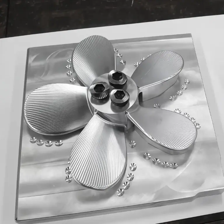
5-axis machining adds two rotary axes so the cutter can approach complex features from different angles. This improves access to deep pockets, compound-angle holes, curved surfaces, and multi-sided components.Another major advantage is setup reduction. Impro notes that true 5-axis machining allows complex contours and deep pockets to be produced while keeping more features in the same setup, improving their geometric relationships.For aerospace parts, this can reduce fixture transfers and shorten long-reach tooling. 5-axis machining is most valuable when those benefits solve a real geometric or tolerance problem rather than simply adding machine complexity.
Precision CNC Turning And Mill-Turn Machining
CNC turning is used for shafts, pins, bushings, sleeves, fittings, and other rotational aerospace components. It provides efficient control of diameters, shoulders, grooves, threads, and concentric relationships.Mill-turn equipment combines turning with milling, drilling, and multi-axis positioning. This can reduce setups when a cylindrical component also contains flats, cross holes, ports, or other non-rotational features.Reducing setup changes can improve both productivity and feature relationships. The process is especially useful when bore concentricity and later milled features must remain tied to one rotational datum.
Drilling, Boring, Reaming, Grinding, And Finishing
Drilling creates holes, while boring and reaming improve diameter, straightness, or positional accuracy where the functional requirement is tighter. Aerospace hydraulic and structural parts often rely on these processes for fastener, bearing, or fluid-system features.Grinding may be used after turning, heat treatment, or other processes when the required size and surface condition exceed what standard cutting can provide efficiently. It is particularly useful on precision shafts and hardened components.These secondary processes should be planned from the beginning. Leaving incorrect machining allowance or scheduling heat treatment too late can make final finishing unnecessarily difficult.
How Is The Aerospace CNC Machining Process Planned?
Aerospace machining begins with process planning rather than cutting. Drawing review, datum strategy, DFM, material condition, workholding, roughing sequence, toolpath design, tool-life management, and in-process verification all influence whether the final part remains stable and repeatable.
Drawing Review, DFM, And Datum Strategy
The first step is to identify functional surfaces, datum references, critical dimensions, GD&T, coatings, and inspection requirements. These features determine how the part should be located during machining and later measured.DFM review should identify avoidable manufacturing difficulty. Deep narrow pockets, small internal radii, inaccessible holes, unnecessarily tight tolerances, and thin unsupported walls can increase both risk and cost.The machining datum strategy should follow the part’s functional logic whenever possible. JLYPT specifically treats datum planning and GD&T as central to protecting aerospace geometry through machining and inspection.
Material Preparation And Workholding
Raw material should be confirmed for grade, condition, dimensions, and any traceability requirements before the first setup. Material orientation and available stock can affect both workholding and final distortion.Fixtures must hold the part rigidly without blocking the required cutter access. For 5-axis machining, fixture clearance becomes especially important because the spindle and holder may approach from several directions.Thin-wall parts require more careful support. Excessive clamping can temporarily distort the workpiece, causing dimensions to move after it is released from the fixture.
Roughing, Semi-Finishing, And Finish Machining
Roughing removes the majority of stock while preserving enough structural support to keep the part stable. Toolpaths should avoid concentrating excessive heat or cutting force in one region.Semi-finishing produces a more uniform stock condition before final passes. This is useful on complex surfaces and thin walls because the finishing tool encounters more predictable cutting loads.Final machining establishes the critical dimensions and surface quality. Sensitive features are often completed after most high-force stock removal is finished so they are less affected by later machining stress.
Toolpath, Tool Life, Coolant, And In-Process Probing
Toolpaths should maintain stable engagement and avoid unnecessary air cutting, sudden direction changes, or poor chip evacuation. CAM strategy is particularly important when titanium, Inconel, deep cavities, or 5-axis motion are involved.Tool-life control becomes a quality issue when cutting difficult materials. A tool that remains usable for roughing may no longer be suitable for a final surface or precision dimension.In-process probing can confirm workpiece position, critical features, or movement before final cutting. This does not replace final inspection, but it can detect process drift early enough to prevent additional machining on an incorrect reference.
What Are The Main Challenges In Aerospace Machining?
The most common aerospace machining risks come from lightweight geometry, difficult materials, demanding datum relationships, and surface requirements. Process planning must control distortion, tool wear, heat, burr formation, chip evacuation, and setup variation before these issues become inspection failures.
Thin-Wall Distortion And Residual Stress
Weight reduction often creates thin walls and large pocketed structures. As stock is removed, stiffness decreases and residual stresses inside the material can redistribute.A part may appear correct while clamped and then move after fixture release. This makes free-state condition important when evaluating thin aerospace structures.Balanced roughing, stable material, controlled workholding, and suitable finishing allowance help reduce distortion. The machining sequence should preserve support until the most sensitive features are ready to be finished.
Deep Pockets, Tool Access, And Chip Evacuation
Deep cavities reduce weight but create tool-reach and chip-removal problems. Long cutters are less rigid and more likely to deflect or chatter under cutting load.5-axis positioning can improve access by tilting the workpiece or tool, allowing shorter cutters in some situations. Impro also notes that 5-axis orientation can help chip evacuation from deep pockets by improving cutting position.Chip control should be treated as part of the process design. Recut chips can damage surfaces, increase heat, and shorten tool life even when the programmed toolpath itself is correct.
Titanium And Inconel Machining Challenges
Titanium has poor thermal conductivity, so a significant amount of cutting heat remains near the tool edge. This accelerates wear and makes coolant delivery, engagement, and tool condition important.Inconel remains strong at elevated temperature and is prone to work hardening. Unstable cutting or rubbing can make the next pass even more difficult and reduce predictable tool life.Both materials reward stable, conservative process control rather than maximum cutting speed. Impro and Olson both emphasize the substantial machining differences between aluminum, titanium, and nickel-based superalloys.
Burrs, Surface Integrity, And Multi-Setup Accuracy
Burrs commonly form around cross holes, sharp edges, slots, and intersecting features. On aerospace components, uncontrolled manual deburring can be just as risky as leaving the burr because it may change a critical edge or local dimension.Surface integrity also includes roughness, heat-affected condition, scratches, and machining marks. Features exposed to fatigue, sealing, or sliding contact may require more controlled finishing than nonfunctional surfaces.
Common machining risks include:
- Part Distortion:Thin structures may move as heavy stock is removed.
- Tool Wear:Titanium and Inconel can shorten predictable tool life.
- Poor Chip Evacuation:Deep cavities can trap chips and increase heat.
- Datum Shift:Multiple setups may change feature relationships.
- Burr Formation:Cross holes and critical edges require controlled deburring.
How Are Tolerances, Inspection, And Quality Controlled?
Aerospace quality control connects machining, measurement, surface processing, and documentation. Functional datums and GD&T define what must be controlled, inspection verifies the result, and traceability records provide evidence that the approved manufacturing process was followed.
Functional Datums, GD&T, And Tight Tolerances
GD&T controls relationships between features rather than only individual dimensions. Position, profile, flatness, perpendicularity, parallelism, and runout can be more important than simple ± tolerances.The machining setup should therefore reflect the functional datum structure on the drawing. If manufacturing and inspection establish the part from unrelated references, variation can appear even when individual dimensions seem correct.Tighter tolerances also require greater thermal and fixture stability. Machinist.com emphasizes that aerospace tolerance control depends on process stability, fixturing, measurement, and documented verification rather than machine specification alone.
CMM, Profile, And Surface Roughness Inspection
Coordinate measuring machines can verify hole position, complex profiles, bore relationships, and geometric controls relative to defined datums. They are especially useful for multi-face and 5-axis aerospace parts.Surface roughness should be checked with appropriate measurement equipment where Ra or another parameter is specified. Complex contours may require scanning or profile measurement instead of isolated point checks.Inspection planning should match functional risk. Measuring every surface with the same intensity adds cost without necessarily improving quality, while insufficient inspection on critical features increases escape risk.
Surface Treatments And Dimensional Protection
Aluminum aerospace parts may require anodizing or chemical conversion coating, while stainless components commonly use passivation. Plating, heat treatment, and other external processes may also be specified by the drawing or customer.These processes can change final dimensions or surface condition. Precision bores, threads, sealing faces, and mating areas may require masking or machining allowance before treatment.Finished parts also need protection after inspection. Correct packaging and handling prevent scratches, dents, or contamination from turning a conforming component into a rejected one.
Material Traceability, First Article Inspection, And Quality Records
Material traceability can connect a machined component to a specific heat, lot, or material certificate when the customer requires it. This is particularly important on controlled aerospace production programs.First Article Inspection may also be required to demonstrate that the manufacturing process can produce the complete drawing correctly. AS9102 is widely used for aerospace FAI when specified by the relevant customer or program.These requirements should come from the purchase order and quality clauses rather than being assumed for every aerospace-related job. TiRapid should only commit to documentation that is specifically reviewed and agreed for the project.
How Do Aerospace Machining Services Support Production?
Aerospace machining services should support more than a single prototype. A stable supplier helps move the design from initial validation through small-batch production and repeat orders while preserving machining methods, fixtures, inspection plans, and quality records.
Prototype Machining And Design Verification
CNC prototypes allow engineers to test form, fit, assembly, and function using production-relevant materials. This is useful when material stiffness, thermal behavior, thread quality, or final mounting relationships matter.Early prototypes also expose manufacturing problems that may be difficult to see in CAD. Tool access, unrealistic radii, thin unsupported regions, and difficult inspection features can be corrected before the design is frozen.The goal is not simply to make the first part quickly. Prototype manufacturing should generate useful information that improves the production process.
Low-Volume And Repeat Production
Low-volume production allows the supplier to stabilize machining programs, tooling, fixtures, and inspection routines before larger repeat orders begin. This stage is especially valuable for complex parts with difficult materials.Once the process is proven, repeat production should rely on controlled manufacturing data rather than individual operator memory. Tool lists, setup instructions, offsets, inspection programs, and revision status should remain consistent.Olson emphasizes that moving from first article through pilot and sustained production requires process validation, quality gates, and capacity planning rather than simply increasing order quantity.
Maintaining Process And Lot Consistency
Repeat orders should reproduce both the part and the manufacturing method. Changes in material source, cutting tools, fixtures, programming, or secondary processes can introduce new variation.Inspection data can be used to identify gradual drift before dimensions move outside tolerance. This is more effective than waiting for final inspection to detect a completed batch of nonconforming parts.For buyers, consistency often matters more than one impressive sample. A reliable aerospace machining company should be able to explain how it controls repeat orders and drawing revisions.
What Affects Aerospace Machining Cost And Lead Time?
Aerospace machining cost depends on material, geometry, material-removal volume, tolerance, machine type, tooling, inspection, finishing, and production quantity. A higher hourly machining process can sometimes reduce total cost if it removes setups, simplifies fixtures, or lowers inspection risk.
Material Cost And Machining Difficulty
Aluminum generally offers faster machining and longer tool life than titanium or nickel-based alloys. Difficult materials increase both machine time and consumable tooling cost.Material availability also affects lead time. Aerospace-grade material or a required condition may not be available as quickly as common commercial stock.Certified material requirements can further restrict sourcing options. The purchasing requirement should therefore be confirmed before quotation rather than after machining has already been scheduled.
Part Complexity And Material Removal
Complexity is not determined only by the number of features. Deep pockets, thin walls, internal corners, long-reach machining, and multiple critical datums can have a larger impact than simple feature count.Aerospace parts may also remove most of the starting billet to create a lightweight finished component. This increases cycle time even if the final part is relatively small.DFM can reduce cost without changing function. Improving tool access or increasing a noncritical internal radius may allow a larger, more rigid cutter and reduce machining time.
Tight Tolerances And Inspection Requirements
Tight dimensions require more careful finishing, thermal control, tool monitoring, and measurement. Complex GD&T may also require additional inspection programming and fixturing.Documentation adds another layer of time. First article reports, material traceability, expanded dimensional reports, or special-process certificates require administrative and quality resources in addition to machine time.Buyers should therefore define the real acceptance requirements during quotation. Adding inspection documentation after production begins can affect both price and delivery.
5-Axis Machining, Finishing, And Production Volume
5-axis machining has higher programming and equipment costs, but it can reduce total setup time on complex parts. The value depends on whether multi-axis access actually eliminates fixtures or improves datum consistency.Surface treatments and special processes add external lead time, particularly when approved suppliers or controlled processes are required. Transportation and reinspection should also be considered.Production volume changes the cost structure because setup and programming expenses are spread across more units. A prototype may have a higher unit price even when the actual cutting time per part is modest.
| Cost Factor | Typical Impact | Main Reason |
| Titanium / Inconel | High | Slower machining and higher tool wear |
| Deep Pockets | Medium–High | Longer reach and more machining time |
| Tight GD&T | High | Additional finishing and inspection |
| 5-Axis Geometry | Variable | Higher machine cost but fewer setups |
| Larger Volume | Lower Unit Cost | Setup cost spreads across more parts |
How To Choose An Aerospace Machining Company?
Selecting an aerospace machining company should focus on whether the supplier can machine the geometry, control the material, inspect the critical features, support the required documentation, and repeat the process. Machine ownership alone is not enough to demonstrate aerospace production capability.
Review CNC And 5-Axis Machining Capabilities
Start by matching equipment to the actual part. Review machine travel, rotary capacity, spindle access, available workholding, turning capability, and whether simultaneous 5-axis motion is required.A supplier should be able to explain why a part needs 3-axis, 4-axis, or 5-axis machining instead of automatically quoting the most expensive process. This shows that the process is being selected around manufacturing logic.Capacity also matters when moving from prototype to production. The machine that produces the first part must fit into a realistic production schedule for later orders.
Check Aerospace Material And Complex Part Experience
Ask whether the supplier regularly machines the specific alloy in your drawing. Titanium and Inconel experience should involve demonstrated control of tooling, coolant, heat, and tool life rather than occasional exposure.Part geometry matters as much as material. Deep pockets, thin walls, large aluminum structures, precision bores, and multi-face components each require different experience.Machinist.com similarly stresses that shops experienced in one aerospace part family are not automatically interchangeable with suppliers specializing in another material or application.
Evaluate Inspection, Documentation, And Quality Support
Inspection capability should match the drawing. CMM, surface roughness measurement, calibrated instruments, and appropriate inspection methods may all be needed depending on the project.Buyers should also define required documentation before ordering. Material certificates, dimensional reports, first article documentation, and secondary-process records should be included in the quotation when applicable.For regulated programs, required certifications and flow-down clauses should be confirmed explicitly. They should never be assumed from a supplier’s general statement that it serves the aerospace industry.
Review DFM And Prototype-To-Production Capability
Strong DFM support can reduce machining risk before a drawing reaches production. A supplier should be able to discuss tolerances, wall thickness, corner radii, tool access, datum strategy, and material behavior in practical manufacturing terms.Prototype capability is useful, but production capability requires more. Stable fixtures, controlled machining programs, repeatable inspection, revision management, and capacity planning determine whether the same result can be reproduced later.The best aerospace machining services connect engineering and production rather than treating them as separate activities. That makes design changes easier to evaluate and repeat orders more predictable.
FAQs
What Is The Difference Between Aerospace Machining And Standard CNC Machining?
Aerospace machining often involves more demanding materials, lightweight geometries, tighter functional relationships, and greater documentation requirements than routine commercial CNC work. Depending on the project, buyers may also require material traceability, first article inspection, special-process records, and controlled drawing revisions.
When Should An Aerospace Part Use 5-Axis Machining?
5-axis machining is useful when a component contains features on several faces, compound angles, deep pockets, undercuts, or complex surfaces that would otherwise require many setups. A simpler 3-axis or 4-axis process can be more economical when all critical features remain easily accessible.
Why Are Titanium And Inconel More Expensive To Machine?
Titanium concentrates heat near the cutting edge and requires careful control of engagement and coolant. Inconel combines high strength with work-hardening behavior, increasing cutting forces and tool wear, so both materials normally require slower and more controlled machining than aluminum.
What Information Should I Provide When Requesting Aerospace Machining Services?
Provide the 3D CAD file, dimensioned drawing, material and condition, quantity, surface-finish requirements, coatings or secondary processes, and any inspection or documentation requirements. Clearly identifying critical features and applicable quality clauses helps the supplier build a more accurate manufacturing plan and quotation.
Conclusion
Aerospace machining services combine material knowledge, CNC process planning, multi-axis machining, tolerance control, surface management, inspection, and repeatable production. Reliable results depend on connecting these stages rather than treating them as separate tasks. The right manufacturing plan should protect functional datums, control distortion and difficult materials, verify critical features, and provide the level of traceability required by the specific project while avoiding unnecessary cost on noncritical requirements.
At TiRapid, we provide precision CNC machining and manufacturing services for complex aluminum, titanium, stainless steel, engineering plastic, and multi-sided components. Our 3-axis, 4-axis, and 5-axis machining capabilities support DFM, thin-wall structures, deep pockets, precision features, dimensional inspection, and prototype-to-production manufacturing according to each customer’s drawing and quality requirements.