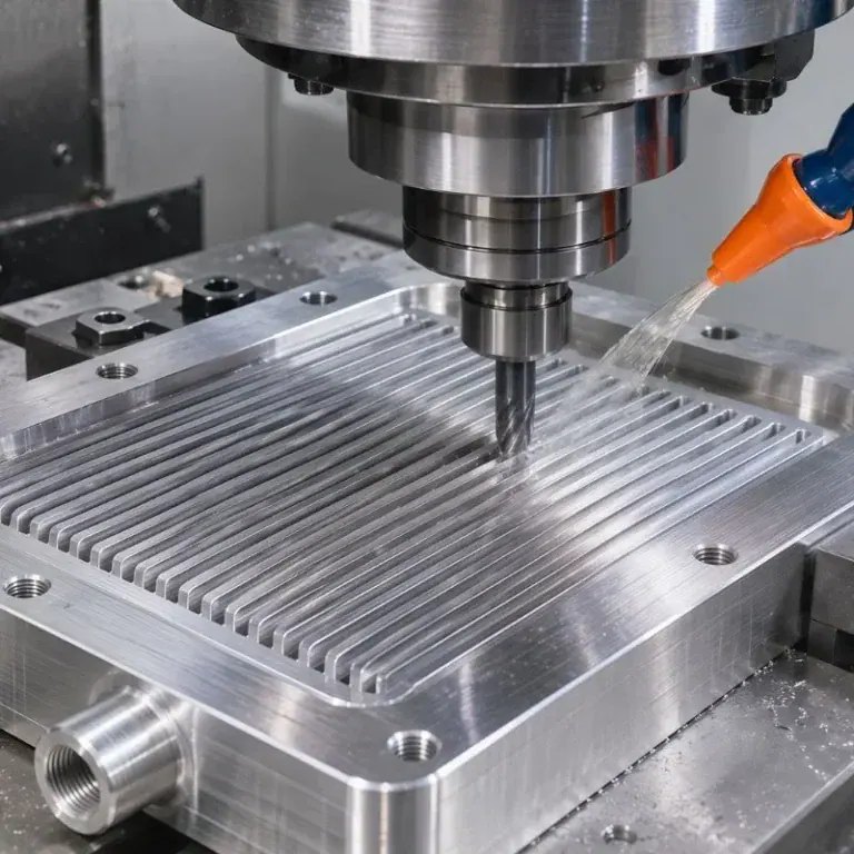
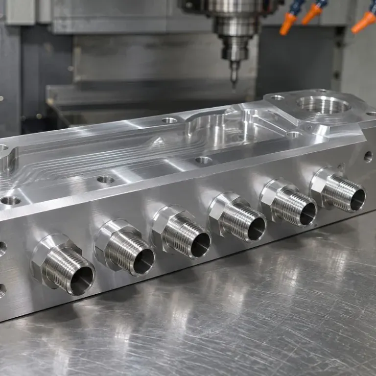
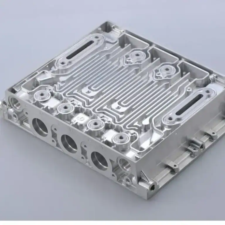
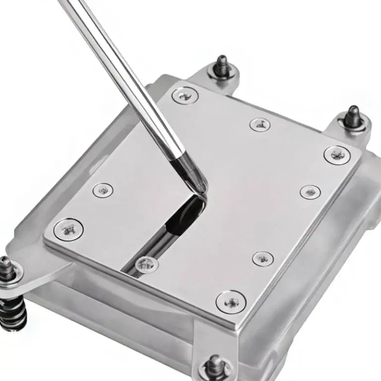
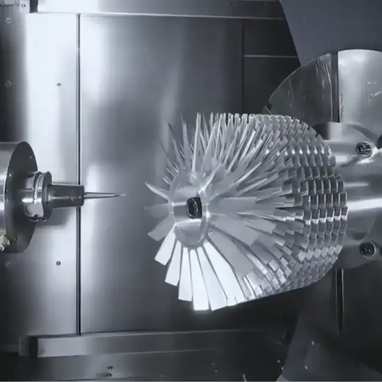
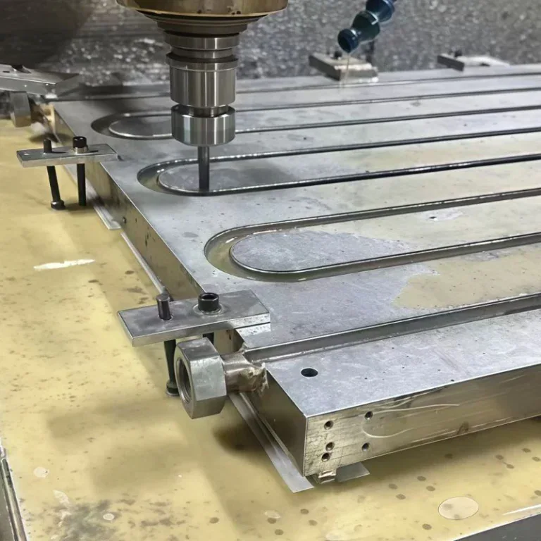
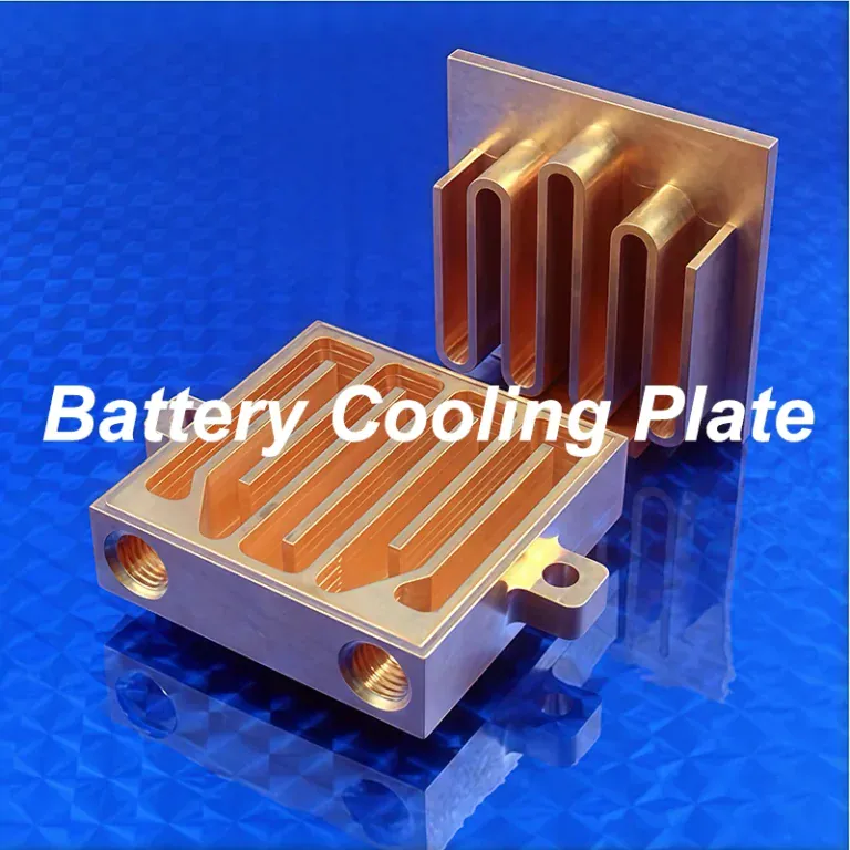
A micro channel cold plate is a precision liquid cooling component that removes heat from high-power electronics through closely spaced internal fluid channels. These channels increase the contact area between the coolant and the metal, making the technology useful for CPUs, GPUs, AI servers, and other equipment with concentrated heat loads. However, effective cooling requires more than simply making the channels smaller.
This guide explains how micro channel cold plates work, their main types, materials, and coolant requirements. It also covers microchannel cold plate design, thermal simulation, CNC micro milling, manufacturing challenges, inspection methods, and practical selection considerations.
Get 20% offf
Your First Order
What Is A Micro Channel Cold Plate?
A micro channel cold plate is a liquid-cooled heat exchanger that uses numerous small internal channels to transfer heat from an electronic component into circulating coolant. Its compact structure is designed for applications requiring effective heat removal from a limited contact area.
Unlike a conventional cold plate with relatively large internal passages, a microchannel design uses closely spaced fins or channels to increase the coolant-contacting surface area. This can reduce thermal resistance, provided that flow distribution, channel geometry, and thermal interfaces are properly designed.
The term microchannel does not describe one universally fixed channel width across all industries. Some designs use passages below 1 mm, while others use somewhat larger channels. The relevant dimensions depend on thermal requirements, manufacturing technology, and application-specific terminology.
Main Components And Basic Structure
A micro channel cold plate typically contains a conductive base, microchannels or microfins, a cover, inlet and outlet ports, and a sealing structure. These components form a compact heat exchanger that transfers energy from a solid heat source into flowing liquid.
The base contacts the electronic component through a thermal interface material. Internal fins create additional heat-transfer surfaces, while inlet and outlet cavities guide coolant into and out of the narrow channels.
| Component | Main Function | Critical Design Requirement |
| Base Plate | Conducts heat from the device | Flatness and controlled thickness |
| Microchannels | Transfer heat to circulating coolant | Channel width, depth, and uniformity |
| Cover Plate | Encloses the fluid passages | Structural integrity and sealing |
| Inlet And Outlet | Connect the cooling loop | Flow distribution and connection accuracy |
| Sealing Interface | Prevents coolant leakage | Surface quality and joint integrity |
| Mounting Features | Secure the cold plate | Hole position and contact pressure |
The design must account for how these parts interact. A highly conductive base cannot compensate for poor contact pressure, and precisely machined channels cannot perform reliably if the completed assembly leaks.
Microchannel Cold Plate, MLCP, And Microchannel Lid Terminology
A microchannel cold plate and a microchannel liquid cold plate (MLCP) generally refer to liquid cooling components with fine internal passages. In advanced GPU applications, MLCP often describes a separate cold plate mounted above the semiconductor package.
A microchannel lid (MCL) is different. Its coolant channels are integrated into the chip package lid, potentially eliminating a separate thermal interface between the lid and an external cold plate. This can shorten the heat-transfer path but creates much greater packaging and sealing challenges.
These terms are not always used consistently across technical publications. Engineers should therefore confirm whether the proposed component is a separate cold plate, an integrated package lid, or another microchannel heat exchanger before evaluating its manufacturing requirements.
How Does A Micro Channel Cold Plate Work?
A micro channel cold plate works by conducting heat into a metal base and transferring it to coolant flowing through narrow internal channels. The coolant absorbs this energy and transports it to an external heat exchanger, where the heat is removed from the liquid cooling loop.
The cooling process combines thermal conduction, convection, and fluid circulation. Channel size and flow distribution strongly influence the results, but the complete system must also provide adequate pumping capacity and heat rejection.
Heat Transfer And Thermal Resistance
Heat transfer begins when energy moves from a processor, GPU, or other device into the cold plate through its contact interface. The metal base then conducts heat toward the channel walls, where circulating coolant absorbs it through convection.
Thermal resistance expresses the temperature difference required to transfer a specified heat load. The basic relationship is ΔT = Q × Rθ, where Q is heat transfer rate and Rθ is thermal resistance between the defined measurement points.
For example, a cold plate with a measured thermal resistance of 0.05 K/W would produce a 25°C temperature difference when transferring 500 W under the same defined test conditions. This is an illustrative calculation, not a guaranteed microchannel cold plate performance value.
Coolant Flow Through Microchannels
Coolant enters an inlet cavity and is distributed among numerous narrow channels. As it flows through these passages, it absorbs heat from the surrounding metal and exits through a collection region.
Small hydraulic dimensions and increased wetted surface area can improve convection. However, microchannel flow may remain laminar, depending on fluid properties, geometry, and flow rate. High heat transfer does not require every microchannel to operate under turbulent conditions.
Poor inlet distribution can cause some channels to receive more coolant than others. Engineers therefore evaluate channel resistance, header geometry, and local heat loads together to reduce temperature variation across the heated surface.
Integration With The Liquid Cooling Loop
A microchannel cold plate operates within a complete cooling loop that generally includes a pump, tubing, manifold, heat exchanger, and coolant management components. In data centers, a coolant distribution unit may separate the IT cooling circuit from the facility cooling system.
Smaller channels can increase pressure drop, so replacing a conventional cold plate with a microchannel design may require reassessing pump capacity and branch flow distribution. The available flow must be evaluated at the operating pressure of the complete system.
Coolant cleanliness also becomes more important as channel dimensions decrease. Suitable filtration, flushing, material compatibility, and air removal help protect the plate against blockage and unstable cooling performance.
What Are The Main Types Of Micro Channel Cold Plates?
The main types of micro channel cold plates include separate direct-to-chip cold plates, integrated microchannel lids, and customized microchannel structures. They differ in where the coolant channels are located, how heat reaches them, and how the components are manufactured.
No single construction suits every thermal application. The right design depends on the electronic package, cooling capacity, available space, and acceptable manufacturing complexity.
Direct-To-Chip Microchannel Cold Plates
Direct-to-chip microchannel cold plates are separate cooling assemblies mounted against a chip package or other concentrated heat source. Their internal channels are positioned close to the contact surface to reduce the conduction path.
These cold plates commonly use a copper or other conductive metal base, combined with a sealed cover and external coolant connections. The chip package usually remains unchanged, simplifying integration compared with redesigning the semiconductor lid.
This approach is useful for AI processors, high-power GPUs, and CPUs that require additional heat-transfer capability. Its effectiveness depends on the channel arrangement, coolant flow, mounting pressure, and resistance of the thermal interface.
Microchannel Lids And Integrated Cooling Designs
A microchannel lid integrates liquid cooling passages into the chip package lid itself. By placing coolant closer to the die, it can remove an interface layer present in conventional cold plate assemblies.
However, semiconductor package-level cooling demands precise alignment, strict control of mechanical loading, and reliable fluid sealing close to sensitive electronic components. Thermal expansion and package deformation also become important design constraints.
Integrated cooling structures therefore involve more than ordinary metal machining. They require close coordination with chip packaging, materials engineering, assembly processes, and reliability validation.
Microchannel Vs. Conventional Cold Plates
Microchannel and conventional cold plates perform the same basic function, but their internal geometries differ. Conventional designs often use larger milled channels, embedded tubes, or other flow passages, while microchannel designs concentrate more heat-transfer surface into a smaller region.
Microchannels may achieve lower thermal resistance for demanding heat sources. Their tradeoffs include higher flow resistance, stricter cleanliness requirements, more difficult fabrication, and additional inspection effort.
| Comparison | Microchannel Cold Plate | Conventional Cold Plate |
| Internal Geometry | Dense, small passages or fins | Usually larger flow passages |
| Heat-Transfer Area | High within a compact region | Depends on channel design |
| Pressure Drop | Can be higher at comparable flow | Often easier to manage |
| Manufacturing | Fine-feature fabrication required | Generally more accessible |
| Cleanliness Sensitivity | High | Often lower |
| Typical Selection | High heat-flux electronics | Broad industrial cooling applications |
The final decision should be based on measured thermal resistance and pressure-drop curves rather than assuming that smaller channels always deliver better system performance.
What Materials And Coolants Are Used For Micro Channel Cold Plates?
Micro channel cold plates commonly use copper or aluminum for their conductive structures and treated water or compatible water-glycol mixtures as coolant. Material and fluid selection must consider thermal conductivity, corrosion, sealing compatibility, and manufacturing requirements.
The plate material affects conduction and machining behavior, while the coolant influences convection, pressure drop, corrosion risk, and operating temperature limits. Both must be selected as parts of the same thermal system.
Copper And Aluminum Cold Plates
Copper is commonly selected for compact, high-heat-flux cold plates because of its high thermal conductivity. High-conductivity copper can approach 390 W/(m·K) near room temperature, depending on the grade and material condition.
Aluminum is considerably lighter and generally easier to machine economically. For comparison, 6061 aluminum has a typical thermal conductivity around 167 W/(m·K), although actual values vary with temper and specification.
| Material | Approximate Thermal Conductivity | Main Advantage | Manufacturing Consideration |
| High-Conductivity Copper | 390 W/(m·K) | High heat conduction | Burrs, tool wear, and material cost |
| 6061 Aluminum | 167 W/(m·K) | Lightweight and machinable | Lower conductivity and coolant compatibility |
Copper may be preferable when the thermal path must be very compact. Aluminum can be a practical choice when weight, size, and cost requirements allow its lower conductivity to be compensated through suitable geometry.
Coolant Selection And Material Compatibility
Treated water is often used because it provides good heat capacity and relatively low viscosity. Inhibited glycol mixtures may be appropriate when freeze protection, corrosion control, or specific operating conditions require them.
However, glycol concentration changes fluid properties. Higher viscosity can increase pumping requirements, while different coolant formulations affect heat capacity and material compatibility. Performance should therefore be calculated using the intended operating fluid.
Engineers must also consider mixed-metal corrosion and seal compatibility. The coolant, plate body, cover, joints, connectors, and other wetted components should be assessed together rather than assuming that one fluid will work safely with every material combination.
How Do You Design A Micro Channel Cold Plate?
A micro channel cold plate is designed by defining the heat load, allowable temperature, coolant conditions, channel geometry, and pressure-drop limit. Engineers then optimize the flow path and verify performance using thermal and fluid simulations before manufacturing prototypes.
Good design balances thermal resistance with pumping demand and manufacturability. Extremely narrow channels may improve local heat transfer but become impractical when cutting-tool access, cleaning, or sealing requirements are considered.
Channel Geometry, Fin Size, And Heat Transfer
Channel geometry determines how much heat-transfer surface is exposed to the coolant and how heat spreads from the base into the fins. Width, depth, length, spacing, and fin thickness all affect thermal behavior.
Increasing channel density can improve surface area, but thinner fins may conduct heat less effectively if they become too tall or mechanically fragile. The base thickness must also be sufficient for structural strength while limiting unnecessary conduction resistance.
Manufacturing constraints should be included early. A channel pattern that performs well in simulation may be difficult to machine consistently if it requires excessive depth-to-width ratios, fragile cutters, or inaccessible internal corners.
Coolant Flow Rate And Pressure Drop
Coolant flow rate determines how quickly heat is transported out of the cold plate. Pressure drop describes the resistance encountered as coolant passes through the internal channels, manifolds, and connections.
For example, when water absorbs 300 W at a flow rate of 1 L/min, its ideal bulk temperature rise is approximately 4.3°C. This calculation assumes steady conditions and water properties near room temperature, it does not predict the chip temperature.
At the same flow rate, smaller hydraulic passages generally increase fluid resistance. Engineers must evaluate the pressure-drop curve alongside the thermal performance curve to find an acceptable operating point for the actual pump and cooling loop.
Thermal Simulation And Flow Analysis
Thermal simulation and computational fluid dynamics (CFD) help engineers evaluate temperature distribution, coolant velocity, pressure loss, and local flow behavior before manufacturing the part.
The model should represent the actual heat-source layout, inlet temperature, coolant properties, contact resistance, and boundary conditions. Results based on unrealistic uniform heating or idealized interfaces may not predict performance in the finished equipment.
Simulation is most valuable when followed by physical validation. Prototype testing can reveal discrepancies caused by surface contact, manufacturing variation, coolant distribution, or assembly details that were simplified in the model.
How Are Micro Channel Cold Plates CNC Machined?
Micro channel cold plates can be CNC machined by milling fine internal channels and fins into a conductive metal base, then machining the ports, sealing features, and mounting interfaces. Additional joining, cleaning, and inspection steps are required before the finished assembly can operate safely.
CNC micro milling is suitable for accessible channel designs and customized prototypes. Other fabrication methods may be more economical for extremely fine features or high production volumes, so process selection should follow a design-for-manufacturing review.
CNC Micro Milling Of Cooling Channels And Fins
CNC micro milling uses small cutting tools and controlled machining parameters to form narrow passages in copper or aluminum. Accurate toolpaths help maintain consistent channel spacing and geometry.
Cutting forces, tool runout, chip evacuation, and burr formation become increasingly important as feature size decreases. Copper may produce ductile burrs, while thin aluminum fins can deform if the tool or workpiece is insufficiently supported.
Tool diameter, available cutting length, and machine capability determine what channel geometry can be produced reliably. Engineers should avoid specifying channel dimensions that cannot be verified or repeated consistently during production.
Precision Machining Of Ports And Sealing Surfaces
Ports, sealing grooves, and mounting surfaces require accurate machining because they determine coolant connections, assembly fit, and the integrity of the completed cold plate.
Drilling and tapping may be used for connection ports, while precision milling creates contact faces and sealing features. Thread standards, O-ring geometry, and mating-surface requirements must be defined on the approved engineering drawing.
Critical machining controls include:
- Channel Dimensions:Control passage width, depth, and fin spacing.
- Contact Flatness:Maintain the specified thermal contact geometry.
- Port Accuracy:Match connection threads and fitting locations.
- Sealing Features:Produce the required groove profile and surface finish.
- Burr Control:Prevent loose particles from entering the cooling passages.
Tolerances should reflect functional requirements. Applying unnecessarily tight specifications to noncritical features increases cost without necessarily improving thermal performance.
Joining, Sealing, And Internal Cleaning
Microchannels must be enclosed using a suitable joining or sealing method. Depending on the material and design, manufacturers may use brazing, diffusion bonding, friction stir welding, or mechanically fastened covers with compatible seals.
Each process has limitations. Brazing filler can obstruct narrow channels if poorly controlled, while joining heat may distort the base. Mechanical seals require suitable compression, surface quality, and resistance to coolant exposure.
Cleaning is essential after machining and joining. Chips, burrs, flux residue, and other particles must be removed without damaging delicate fins or coatings. The completed assembly must then be tested against its specified leakage requirements.
Manufacturing Challenges And Cost Considerations
The main manufacturing challenges include maintaining small-channel dimensions, preventing fin damage, controlling joining defects, and inspecting features that become inaccessible after the cover is attached.
Cost rises when channel density requires smaller tools, slower feed rates, additional setups, or more demanding cleaning and inspection. Prototype cost may also include process development and adjustments to the channel geometry.
A practical DFM review evaluates:
| Design Feature | Manufacturing Risk | Possible Engineering Response |
| Very Narrow Channels | Tool breakage and burrs | Review minimum width and cutter access |
| Deep Microchannels | Deflection and chip accumulation | Adjust channel depth or fabrication method |
| Thin Fins | Bending or fracture | Increase support or revise fin geometry |
| Complex Internal Paths | Limited machining access | Consider multi-piece construction |
| Tight Sealing Features | Leakage from dimensional variation | Define functional tolerances and inspection |
| High Channel Density | Long cycle time | Balance thermal gain against machining cost |
The objective is not simply to produce the finest possible channels. It is to manufacture a design that meets thermal requirements repeatedly and at an acceptable cost.
How Are Micro Channel Cold Plates Tested?
Micro channel cold plates are tested through dimensional inspection, cleanliness checks, pressure and leak testing, and thermal performance validation. Thermal cycling or shock tests may also be required to verify reliability under changing operating temperatures.
Dimensional Inspection And Channel Cleanliness
Dimensional inspection verifies contact surfaces, port positions, mounting features, and channel geometry before the passages are permanently enclosed.
Optical measurement, profilometry, coordinate measurement, or suitable specialized inspection methods may be used depending on feature size. Hidden channels can be difficult to inspect after joining, so intermediate checks are especially important.
Cleanliness verification confirms that cutting debris, joining residues, and other contaminants have been removed. The required particle limits and cleaning procedures should be established according to the narrowest passages in the cooling system.
Pressure Testing And Leak Testing
Pressure testing verifies that the completed cold plate can withstand a specified internal pressure without unacceptable deformation or structural failure. Leak testing determines whether fluid escapes through joints, ports, or other defects.
Hydrostatic testing, pressure decay, and helium-based leak detection may be used, depending on the assembly and required sensitivity. Structural proof testing and leakage measurement are different evaluations and should not be treated as interchangeable.
Test pressure, duration, fluid, temperature, and acceptance limits must be defined by engineering requirements. A universal pressure multiplier should not be applied without considering material strength, joining methods, and the product’s rated pressure.
Thermal Shock And Cooling Performance Testing
Thermal shock or thermal cycling tests evaluate how repeated temperature changes affect joints, seals, and the cold plate structure. Different expansion rates between materials can create stress during heating and cooling.
Cooling performance testing measures temperatures, coolant flow, and pressure drop under controlled thermal loads. Results are commonly presented as thermal resistance versus flow rate and pressure drop versus flow rate.
These measurements help engineers compare the prototype against simulation results. They also provide useful baseline data for monitoring manufacturing consistency across production batches.
Where Are Micro Channel Cold Plates Used?
Micro channel cold plates are used in systems that generate high heat loads within limited space, particularly AI servers, high-power GPUs, CPUs, and specialized electronic equipment. They are also applicable to selected industrial, automotive, and energy applications requiring compact liquid cooling.
AI Servers And High-Power GPU Cooling
AI servers use high-power processors and accelerators that can create concentrated thermal loads. Microchannel cold plates help remove heat close to these sources while supporting densely packed server designs.
Next-generation GPU platforms increase interest in fine-channel cooling, but the exact cold plate architecture depends on the processor package and system supplier. Public discussion of NVIDIA Rubin, for example, does not establish a universal microchannel specification or an approved supplier list.
For server designers, the main engineering questions are whether the cold plate meets the chip temperature limit, whether the CDU provides sufficient flow and pressure, and whether cleanliness and maintenance requirements can be satisfied.
CPUs And Other High-Heat-Density Electronics
Microchannel cold plates can also be used for high-performance CPUs, power electronics, laser modules, and other devices with localized heat generation. These applications benefit when the thermal contact area is limited.
For multi-component assemblies, the channel layout may need to match several heat sources rather than a single central hotspot. Customized flow distribution can help control temperature differences between components.
In industrial and energy systems, vibration, mechanical loading, coolant exposure, and service conditions may be as important as maximum cooling capacity. The cold plate must therefore be designed for both thermal and mechanical reliability.
What Are The Advantages And Limitations Of Micro Channel Cold Plates?
Micro channel cold plates offer high heat-transfer area, compact construction, and the potential for lower thermal resistance. Their main limitations are increased pressure drop, clogging sensitivity, manufacturing complexity, and stricter maintenance requirements.
These advantages are most valuable when conventional cooling solutions cannot meet the thermal target within the available space. The performance improvement must justify the added system and manufacturing demands.
Cooling Efficiency And Compact Design Benefits
Microchannels provide a large coolant-contact area within a relatively small metal base. This can improve heat removal from concentrated thermal sources without requiring a large external heatsink.
By placing coolant closer to the heat source, a well-designed plate may reduce conduction resistance through the base. The improvement depends on material conductivity, channel geometry, and how heat reaches the coolant.
A compact plate can also support denser electronic packaging. However, cooling efficiency should be evaluated using measured thermal resistance at the intended flow rate, not merely by counting channels or reducing their dimensions.
Pressure Drop, Clogging, And Maintenance Challenges
Narrow passages resist coolant flow and can create higher pressure drop than larger conventional channels. This increases the importance of pump selection and the overall hydraulic design.
Fine channels are also more sensitive to particles and deposits. Poor cleaning, incompatible coolant, or corrosion products may obstruct passages and create localized hot spots.
Maintenance planning should therefore include coolant monitoring, suitable filtration, controlled flushing, and periodic inspection. A microchannel cold plate offers its greatest value when the complete system is designed to support its narrower passages.
How Do You Choose The Right Micro Channel Cold Plate?
The right micro channel cold plate should meet the required heat load and temperature limit while remaining compatible with the coolant loop, electronic package, manufacturing process, and project cost. Standard designs are suitable for common interfaces, while custom plates support unusual geometries and higher integration demands.
Selection should follow measured thermal and hydraulic requirements. The most sophisticated channel pattern is not necessarily the best option if a simpler cold plate already meets the operating limits.
Standard Vs. Custom Microchannel Cold Plates
A standard cold plate is usually preferable when its dimensions, mounting interface, thermal resistance, and pressure drop match the application. It reduces development effort and avoids unnecessary customization.
A custom design is valuable when heat sources are unevenly distributed, ports must be relocated, or the cold plate must fit a restricted enclosure. Engineers can adjust channel geometry, contact surfaces, and mounting features to match those constraints.
Before selecting a custom design, the team should establish thermal targets, available pump head, material compatibility, and realistic tolerances. These requirements help prevent unnecessary complexity during prototyping and manufacturing.
Manufacturing Feasibility And Supplier Selection
A suitable supplier should be able to review channel geometry, confirm manufacturing capabilities, and explain how critical features will be inspected. Machining fine channels is only one part of the broader manufacturing challenge.
For copper and aluminum components, relevant capabilities may include CNC micro milling, precision drilling, sealing-surface machining, deburring, cleaning, and dimensional inspection. Joining and full-assembly testing must be confirmed separately.
When assessing suppliers for advanced GPU cooling, buyers should request measurable thermal and pressure-drop data, materials documentation, process controls, and evidence of qualification where required. Marketing claims about supporting particular chip platforms should not replace documented verification.
FAQs
Can A Micro Channel Cold Plate Operate Below Ambient Temperature?
Yes, but only when the cooling system supplies coolant below ambient temperature. The cold plate itself does not actively refrigerate the liquid. For example, circulating coolant at 15°C in a 25°C environment may create surfaces below room temperature. Engineers must then consider condensation, which occurs when a surface falls below the surrounding air’s dew point. Insulation, humidity control, and appropriate coolant temperature settings are necessary to prevent moisture from reaching sensitive electronics.
How Much Does Channel Size Variation Affect Cold Plate Performance?
Channel size variation can change local flow resistance and coolant distribution. In an idealized laminar rectangular passage, resistance is highly sensitive to channel dimensions, reducing a narrow dimension by 10% can increase resistance substantially. The exact effect depends on channel aspect ratio, surface condition, and flow regime. For this reason, engineers should control channel width and depth according to the design’s hydraulic sensitivity rather than applying arbitrary tolerances to all features.
Can Microchannel Cold Plates Be Repaired After A Coolant Leak?
Repair depends on the source of leakage and how the cold plate was assembled. A damaged external O-ring or removable fitting may be replaceable, while a failed brazed or diffusion-bonded internal joint can be difficult to repair reliably. After any repair, the assembly should undergo the specified pressure and leakage tests. For critical electronics, replacement may be more practical when the original joint cannot be inspected or validated to the required standard.
What Is The Difference Between A Prototype And A Production Microchannel Cold Plate?
A prototype validates geometry, coolant flow, and thermal performance, while a production design must also demonstrate repeatable manufacturing quality. One successful sample does not establish process capability. Production evaluation should include dimensional variation, tool wear, joining consistency, cleaning effectiveness, and inspection records. For example, comparing thermal resistance and pressure-drop results across multiple parts can reveal channel or assembly variation that a single prototype would not expose.
Conclusion
A micro channel cold plate improves liquid cooling by placing a large heat-transfer area close to demanding electronic heat sources. Its performance depends on channel geometry, material conductivity, coolant flow, pressure drop, and reliable thermal contact. CNC machining enables precise custom channels and mechanical interfaces, but engineers must also account for joining, cleaning, inspection, and testing. The best design balances cooling performance with manufacturability, cost, and long-term operating reliability.
At TiRapid, we provide precision CNC machining and manufacturing services for custom copper and aluminum components. Our CNC milling, multi-axis machining, DFM support, and dimensional inspection help customers produce accurate channels, mounting features, and sealing interfaces for demanding thermal management applications.