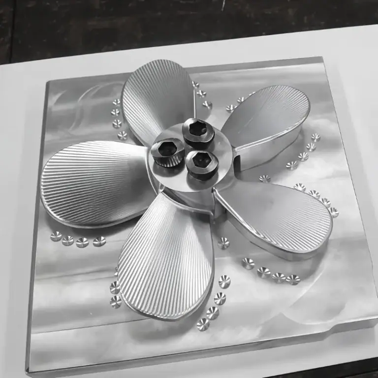
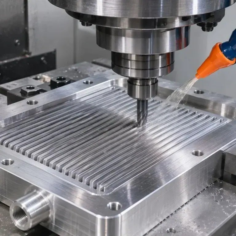
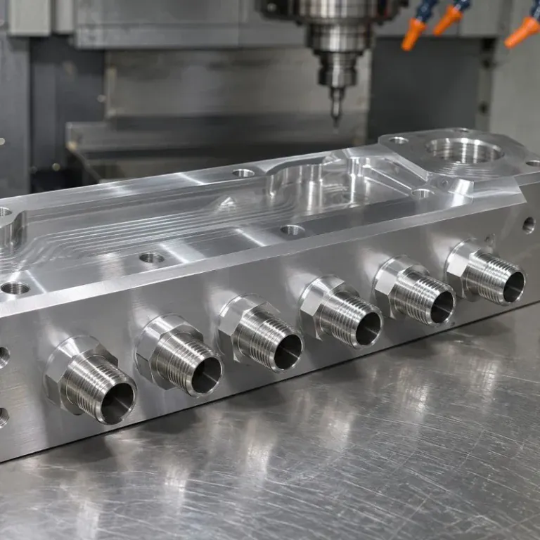
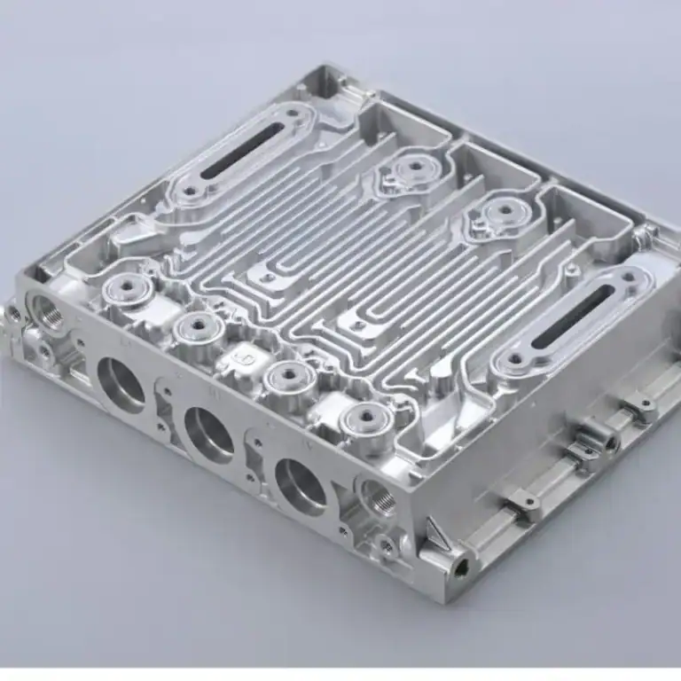
Propeller machining is the process of manufacturing or finishing propeller blades, hubs, shafts, and mounting features to meet specified dimensions and surface requirements. Because propeller blades contain twisted profiles, variable curvature, and complex transitions, machining accuracy directly affects blade geometry, balance, and assembly fit. CNC milling, particularly 5-axis machining, is widely used to control these demanding features.
This guide explains propeller machining methods, suitable materials, and the complete CNC manufacturing process. It also covers the differences between CNC and manual machining, toolpath planning, blade pitch measurement, machining challenges, dimensional inspection, and quality control.
What Is Propeller Machining?
Propeller machining is a precision manufacturing process that removes material from a casting, forging, or solid workpiece to create the specified blade surfaces, hub features, and mounting geometry. It uses CNC turning, milling, multi-axis machining, and controlled finishing to achieve the required dimensional and surface accuracy.
Main Propeller Components And Blade Geometry
A propeller consists primarily of blades and a central hub. Important blade features include the pressure face, suction back, leading edge, trailing edge, root fillet, and tip. The hub contains the mounting interface that connects the assembly to its shaft or drive system.
Blade geometry is described using diameter, pitch, chord length, thickness distribution, rake, and skew. These parameters determine how the blade interacts with the surrounding fluid and how mechanical loads are transferred into the hub.
For machining, the blade root and curved surfaces are particularly demanding. Their changing curvature and restricted tool access require accurate CAD geometry, stable workholding, and carefully planned finishing operations.
How Blade Pitch And Profile Affect Performance?
Blade pitch is the theoretical axial distance a propeller advances in one revolution without slip. Blade profile describes the shape and thickness of individual sections. Both influence thrust generation, hydrodynamic loading, cavitation behavior, and vibration.
At a particular radius, geometric pitch is related to the local pitch angle. Different blade sections can have different pitch angles, even when the propeller is designed with an approximately constant pitch.
Machining errors can change local blade angles or thickness distribution. These differences may alter the intended flow and loading, making accurate profile reproduction important for consistent propeller performance.
Which Propeller Components Can Be CNC Machined?
CNC machining can manufacture or finish propeller blades, hubs, shaft bores, mounting interfaces, shafts, and selected prototype components. The appropriate process depends on component dimensions, material, surface complexity, and whether the work involves a new part or an existing casting.
CNC milling is typically used for complex blade surfaces, while CNC turning and boring are often suitable for rotational features.
Marine Propeller Blades And Hubs
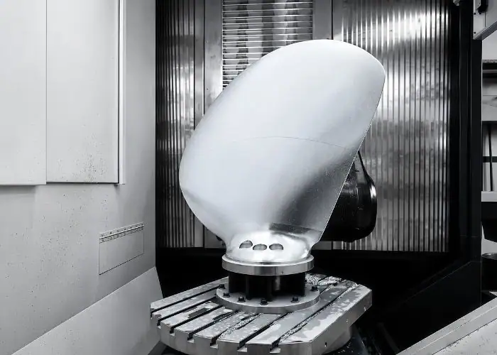
Marine propeller blades and hubs are important applications of precision CNC machining. A cast propeller may require significant material removal before its final blade geometry and mounting surfaces meet the design.
Blade machining involves the pressure face, suction back, root transitions, and outer edges. Because these surfaces have varying curvature, tool orientation must be controlled to avoid interference and unwanted profile errors.
The hub usually requires machined end faces, bores, tapers, or other locating features. Establishing the hub axis accurately provides a reliable reference for subsequent blade operations and final inspection.
Propeller Shafts And Mounting Interfaces
Propeller shafts are primarily rotational components, making CNC turning suitable for producing shaft diameters, shoulders, threads, tapers, and bearing interfaces.
Mounting features may also include keyways, flanges, bolt holes, and precision contact surfaces. These features must be manufactured in accordance with the selected coupling and shaft connection design.
The most important requirements are functional fit and alignment. A precisely machined blade cannot compensate for a hub bore or shaft interface that creates unacceptable eccentricity or assembly problems.
Custom Propellers And Prototype Components
Custom propellers and prototype components can be CNC machined when an existing design is unsuitable or a new geometry requires evaluation. Examples include small propellers, experimental blades, model-scale components, and specialized mechanical interfaces.
Machining directly from solid stock may be practical for prototypes or small components because it avoids some tooling requirements associated with casting. However, material utilization and machining time can be significantly higher.
A prototype should reproduce the intended functional features rather than simply resemble the final part. Important considerations include blade thickness, mounting accuracy, surface condition, and compatibility with the planned inspection method.
What Materials Are Used In Propeller Machining?
Common propeller machining materials include nickel-aluminum bronze, manganese bronze, stainless steel, aluminum alloys, and selected titanium alloys. Material selection depends on corrosion resistance, strength, fatigue performance, weight, operating environment, and machining cost.
Marine propellers commonly use copper-based alloys because they provide a useful combination of corrosion resistance and mechanical performance. Other materials may be better suited to smaller, specialized, or nonmarine applications.
Bronze And Copper Alloys For Marine Propellers
Nickel-aluminum bronze is widely used in marine propulsion because it combines good corrosion resistance with strength and durability. Manganese bronze and related copper alloys are also used for propeller manufacturing.
These materials are commonly supplied as castings. The machining plan must account for the material condition, casting allowance, potential surface defects, and the geometry of the finished blades.
Cutting parameters and tooling should be selected for the particular alloy. Even closely related copper alloys can differ in hardness, cutting behavior, and tool wear, so one machining strategy should not automatically be applied to every bronze grade.
Stainless Steel, Aluminum, And Titanium Alloys
Stainless steel may be selected for propellers or related components where its strength, corrosion resistance, or application requirements justify its use. Machining conditions depend on the specific stainless steel grade.
Aluminum alloys offer lower density and relatively efficient machining, making them attractive for selected lightweight prototypes and components. Their suitability for marine service must be evaluated against corrosion, mechanical loading, and environmental exposure.
Titanium alloys provide high specific strength and corrosion resistance in certain environments, but they are more expensive and difficult to machine. Cutting heat, tool wear, and surface integrity require careful control.
How Material Properties Affect Machinability?
Material properties affect cutting forces, tool wear, surface finish, chip formation, and machining time. Hardness alone is not enough to predict whether a propeller material will be easy to machine.
Thermal conductivity, work hardening, alloy composition, and microstructure can influence the machining process. Castings may also contain variations in machining allowance or localized material conditions.
A useful material comparison is:
| Material | Main Advantage | Machining Consideration | Typical Application |
| Nickel-Aluminum Bronze | Marine Corrosion Resistance | Tool Wear And Casting Variability | Marine Propeller Blades |
| Manganese Bronze | Strength And Marine Service Use | Alloy-Dependent Cutting Behavior | Marine Propellers |
| Stainless Steel | Strength And Corrosion Resistance | Heat And Work Hardening | Specialized Propellers And Shafts |
| Aluminum Alloy | Low Weight And Good Machinability | Burrs And Possible Distortion | Prototypes And Lightweight Parts |
| Titanium Alloy | High Specific Strength | Heat Concentration And Tool Wear | Specialized Components |
Material selection should always follow the approved design and operating requirements, rather than machining convenience alone.
How Do CNC And Manual Propeller Machining Compare?
CNC propeller machining uses programmed tool movements to produce repeatable blade geometry, while manual machining relies more heavily on operator-controlled cutting, grinding, and finishing. CNC is generally better suited to complex, repeatable profiles, while manual methods remain useful for selected corrections and finishing operations.

Conventional Machining And Manual Finishing
Conventional machining is commonly used for accessible hub faces, bores, and other straightforward features. Manual grinding and fitting may also be used for localized adjustments or surface correction.
Manual blade processing requires careful measurement and controlled removal of material. Excessive grinding can change blade thickness, edge shape, or pitch-related geometry, making repeated inspection necessary.
These methods can be valuable for repair and finishing, but they become less efficient when large freeform surfaces must closely match a detailed CAD model across several blades.
3-Axis Vs. 5-Axis CNC Machining
3-axis CNC machines are effective for hub faces, accessible bores, drilling, and selected blade features. They are often economical when the tool can reach the required surfaces without excessive repositioning.
5-axis CNC machines provide additional control over tool orientation. This makes them particularly useful for twisted blades, curved root transitions, and regions where the hub or adjacent blades restrict tool access.
5-axis cnc machining does not automatically guarantee better accuracy. Tool calibration, machine dynamics, fixturing, interpolation, and CAM programming still determine whether the process can reproduce the required geometry.
| Method | Main Strength | Main Limitation | Suitable Work |
| Manual Finishing | Localized Correction | Operator-Dependent Consistency | Repair And Final Adjustment |
| 3-Axis CNC | Efficient Simple Geometry | Restricted Tool Orientation | Hubs And Accessible Features |
| Indexed Multi-Axis CNC | Multiple Controlled Orientations | Limited Continuous Reorientation | Selected Blade Regions |
| Simultaneous 5-Axis CNC | Continuous Tool Orientation | Greater Programming Complexity | Complex Blade Surfaces |
How To Select The Right Machining Method?
The machining method should be selected according to blade geometry, accessibility, dimensional requirements, and production volume. Simple shaft features do not necessarily require 5-axis equipment.
For a complex blade, engineers should examine tool reach, adjacent-blade interference, surface finishing requirements, and the number of setups needed.
An effective process may combine turning for the hub, 3-axis machining for accessible features, and 5-axis finishing for the blades. This approach can reduce unnecessary machine time while preserving the accuracy of critical surfaces.
How Are Propellers CNC Machined?
Propellers are CNC machined through CAD/CAM preparation, workpiece positioning, hub machining, blade roughing, root and edge machining, precision finishing, and dimensional inspection. The operation sequence is designed to maintain accurate references and prevent distortion while material is removed from the workpiece.
In ship propeller machining, the starting material is often a casting with substantial allowance. The machining plan must therefore account for both the final geometry and the condition of the incoming part.
CAD/CAM Programming And Tool Path Planning
CAD/CAM programming converts the propeller’s 3-dimensional geometry into machine toolpaths. Accurate models must define the pressure face, suction back, blade roots, edges, and mounting interfaces.
Toolpath planning determines cutting direction, tool engagement, stepover, machining allowance, and tool orientation. For 5-axis operations, the CAM system must also account for the toolholder, machine limits, and possible interference with neighboring blades.
Simulation is essential for checking collisions, overtravel, and areas of uncut material. The most suitable toolpath follows the actual surface and machine requirements rather than assuming that one universal cutting direction is ideal for every propeller.
Workholding And Propeller Setup
Propeller setup establishes the relationship between the workpiece, machine coordinates, and design datums. The hub axis and selected reference faces are commonly used to create a consistent machining coordinate system.
Fixtures must hold the workpiece securely while allowing the cutting tool to access required surfaces. Large propellers introduce additional challenges because of their mass, blade span, and limited support points.
Before machining, engineers should check clamping stability, workpiece clearance, machine travel, and fixture interference. A setup that is accurate when stationary must also remain stable under cutting forces.
Propeller Hub And Bore Machining
Hub machining commonly includes facing, turning, boring, taper machining, and preparation of keyways or other mounting features. The correct operations depend on the propeller design.
Establishing accurate hub reference surfaces is important because these features influence subsequent setup and the relationship between the propeller and its shaft.
For keyed or keyless interfaces, dimensions must follow the actual assembly specification. The bore geometry, contact area, alignment, and fastening arrangement should not be assumed from a generic propeller design.
Blade Face And Back Rough Machining
Blade rough machining removes excess stock from the pressure and suction surfaces while preserving sufficient material for finishing. Large marine castings may require substantial roughing before the blade profiles approach their final shape.
Machining both sides must be planned carefully because removing material changes local stiffness and can affect workpiece stability.
A balanced roughing strategy reduces heavy localized cuts and preserves support where needed. Intermediate checks can identify unexpected stock variation, casting defects, or geometry that requires adjustment before finishing.
Blade Root, Leading Edge, And Trailing Edge Machining
The blade root connects the blade to the hub and often contains complex fillets. These transitions are difficult to machine because the available tool space may be restricted by adjacent surfaces.
Leading and trailing edges also require controlled machining. Their final shapes must match the approved blade geometry without leaving unintended burrs, flats, or excessive material removal.
Ball-end and other suitable milling tools may be used depending on curvature and access. Cutting strategies should avoid abrupt tool movements, collisions, and excessive cutting loads near thin edge sections.
5-Axis Blade Finishing And Surface Optimization
5-axis blade finishing is used to produce the final freeform geometry with controlled tool orientation. Proper tool positioning can improve access, maintain suitable cutting contact, and reduce unnecessary machining marks.
Finishing parameters include cutter diameter, tool tilt, stepover, feed, and remaining stock. Ball-end milling may be appropriate for curved areas, while other tool types can improve efficiency where the surface geometry permits.
Surface optimization should be verified through measurement rather than visual appearance alone. The finished blade must satisfy the specified profile, thickness, pitch, and surface requirements, without excessive polishing that changes the intended shape.
What Are The Main Challenges In Propeller Machining?
The main propeller machining challenges are complex freeform surfaces, restricted tool access, thin-blade deflection, vibration, pitch errors, and surface defects. These problems require suitable machine capability, stable fixtures, accurate toolpaths, and inspection throughout the manufacturing process.
Complex Curved Surfaces And Tool Accessibility
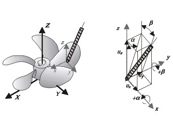
Propeller blades contain continuous changes in curvature, twist, and section thickness. These freeform features are difficult to machine efficiently with a fixed tool orientation.
The hub, adjacent blades, and blade root transitions can restrict access. A toolpath that reaches the outer blade may collide with the workpiece or fixture when approaching the root.
5-axis positioning and collision simulation help address these problems. However, machine travel, spindle clearance, tool length, and fixture design must be checked together before the operation is released.
Thin Blade Deflection And Machining Vibration
Thin propeller blades can deflect under cutting forces, particularly near the tip or other unsupported regions. Excessive deflection may create thickness variation, chatter marks, or profile errors.
The problem becomes more serious as material is removed and blade stiffness decreases. Heavy finishing cuts may therefore produce inconsistent results even when the machine itself is accurate.
Engineers can control this risk by reducing cutting forces, adjusting toolpaths, preserving temporary support where appropriate, and selecting suitable finishing parameters. Inspection should confirm that the blade returns to the required geometry after machining loads are removed.
Blade Pitch Accuracy And Profile Consistency
Pitch accuracy requires the finished blade sections to reproduce the specified angular and geometric relationships. Errors may arise from CAD/CAM data, setup alignment, tool deflection, or incorrect material removal.
Consistency between blades is equally important. Differences in section shape, thickness, or pitch can affect load distribution and may contribute to vibration or unbalanced operating conditions.
Manufacturers should use defined measurement radii and reference datums. Comparing actual measurements with the approved design provides a more reliable evaluation than inspecting only the overall blade appearance.
Surface Finish And Machining Defects
Surface finish affects the quality of the blade boundary and may influence fluid-flow behavior. Tool marks, waviness, burrs, and local surface damage can also reveal machining instability.
Typical causes include unsuitable stepover, tool wear, chatter, poor tool orientation, and inconsistent cutting forces. Surface defects may be particularly difficult to correct near thin edges and curved transitions.
Finishing requirements should be specified according to the application. Excessive polishing is not always beneficial if it changes critical thickness or edge geometry.
| Machining Challenge | Possible Result | Recommended Control |
| Complex Blade Curvature | Profile Deviation | Accurate CAM Toolpaths |
| Restricted Tool Access | Collision Risk | 5-Axis Simulation |
| Thin Blade Deflection | Thickness Error | Controlled Cutting Forces |
| Vibration And Chatter | Surface Waviness | Stable Fixturing And Cutting Parameters |
| Hub Misalignment | Rotational Error | Reliable Machining Datums |
| Excessive Polishing | Geometry Change | Controlled Finishing And Inspection |
How Are Propeller Machining Accuracy And Quality Verified?
Propeller machining accuracy and quality are verified through dimensional inspection, pitch measurement, blade profile comparison, surface assessment, and specified balancing checks. The inspection plan must match the propeller design, applicable standards, and the actual scope of manufacturing work.
Dimensional inspection confirms the geometry of a machined component. Balancing and operating performance evaluation address additional requirements and should not be treated as interchangeable measurements.
Dimensional Inspection Of Hubs And Blade Profiles
Hub inspection checks important dimensions such as bore diameter, taper geometry, end-face alignment, and mounting-feature positions. These features control the mechanical fit between the propeller and its drive system.
Blade inspection evaluates section geometry, thickness, diameter, and specified surface coordinates. Depending on size and accessibility, suitable equipment may include coordinate measuring machines, optical scanning, or specialized propeller measurement systems.
Inspection results should reference the approved CAD model or drawing. Measurement equipment must also have sufficient capability for the specified tolerances.
Propeller Pitch Measurement And Calculation
Propeller pitch can be evaluated by measuring the geometry of defined blade sections. The local pitch angle and measurement radius can be used to calculate geometric pitch.
For a helical reference line, the relationship is:
P = 2πr × tan(β)
Here, P is geometric pitch, r is the distance from the rotational axis, and β is the local pitch angle relative to the plane of rotation.
The same formula applies to an idealized local blade section, but actual inspection must follow the specified reference geometry and measurement procedure. For marine propellers, pitch may be evaluated at several radial positions rather than inferred from a single point.
Surface Quality And Blade Geometry Inspection
Surface inspection checks roughness, tool marks, burrs, waviness, and local damage. Geometric inspection verifies that the finished blade conforms to its intended 3-dimensional form.
A surface with low measured roughness can still have an incorrect profile. Therefore, surface roughness and geometric accuracy must be checked as separate properties.
For applicable marine propellers, ISO 484 provides manufacturing tolerance requirements relating to pitch, blade geometry, and other characteristics. The appropriate standard part, edition, and accuracy class must be confirmed for each project.
Propeller Balancing And Practical Validation
Propeller balancing evaluates mass distribution around the rotational axis. Static balancing identifies certain mass imbalance conditions, while dynamic balancing can assess imbalance behavior during rotation.
Balancing requirements depend on the propeller size, operating speed, assembly configuration, and applicable specification. A dimensionally accurate blade is not automatically balanced.
Practical validation may also involve assembly checks, runout measurements, vibration testing, or performance trials. These activities should be performed by appropriately equipped specialists when required and are separate from ordinary CNC dimensional inspection.
What Affects Propeller Machining Cost And Supplier Selection?
Propeller machining cost depends mainly on material, propeller size, blade geometry, machining time, tolerance requirements, inspection scope, and production quantity. Supplier selection should focus on proven capability for the required component rather than machine specifications or quoted price alone.
The lowest machining price may not include complex inspection, finishing, setup preparation, or specialized handling. These differences should be considered when evaluating a manufacturing proposal.
Material, Blade Complexity, And Machining Time
Material cost depends on alloy type, raw-stock size, availability, and the amount of material removed. Large castings and solid-billet components can have very different manufacturing cost structures.
Blade complexity also affects programming and machine time. Deep root transitions, restricted tool access, and fine finishing requirements generally increase the number of operations.
Tool wear, fixture preparation, and machine capacity may influence the final cost. A small precision propeller and a large marine casting should not be evaluated using the same machining assumptions.
Tolerance, Inspection, And Production Requirements
Tight tolerances increase manufacturing difficulty when they require additional finishing passes, controlled setups, or more detailed inspection.
Inspection costs vary with component size, measurement density, equipment requirements, and documentation. Specialized blade measurement and balancing are distinct services that may need separate planning.
Prototypes, replacement parts, and production batches also have different cost structures. Repeated production can distribute programming and fixture costs across more components, but only when the design and process remain stable.
CNC Machining Capabilities And Supplier Evaluation
A suitable supplier should understand complex surface machining, material behavior, workholding, and the measurement of critical mechanical features. Relevant manufacturing experience is more useful than a general claim of high precision.
For custom propeller blade machining, buyers should consider machine size, axis configuration, CAM capability, maximum workpiece weight, and inspection equipment. Large marine propellers may require specialist facilities beyond ordinary precision job-shop capacity.
Supplier evaluation should distinguish CNC machining from casting, balancing, hydrodynamic testing, and marine certification. A reliable manufacturing plan clearly defines which operations are performed in-house and which require qualified external support.
FAQs
Can A Propeller Be CNC Machined From Solid Metal Instead Of A Casting?
Yes. Small or specialized propellers can be machined from solid metal, particularly for prototypes or low-volume production. For example, machining a blade with an 80 mm overall diameter may avoid the upfront cost of a dedicated casting pattern. However, solid-stock machining removes more material and may require longer machine time. Larger marine propellers are often more economical to produce from castings with suitable machining allowance. Material suitability and structural performance must still be verified.
How Much Machining Allowance Should Be Left On A Propeller Blade?
The finishing allowance depends on material, blade size, casting accuracy, tool diameter, and fixture stiffness. There is no reliable universal value for every propeller. For example, a small prototype might use a final allowance of a few tenths of a millimeter, while a large casting may require a different roughing and finishing strategy. The allowance should be sufficient to remove previous tool marks and geometric errors without creating unnecessary cutting force or blade deflection.
Can A Damaged Propeller Be Re-Machined After Repair?
Yes, some damaged propellers can be re-machined after an approved repair, provided sufficient material and structural integrity remain. Common work may involve restoring bolt holes, mounting faces, or localized blade geometry. The repair procedure must account for the original alloy, damage location, and any welding or heat-related changes. After machining, the repaired area requires dimensional inspection and any additional checks specified by the repair authority. Severe damage may make replacement safer than further material removal.
Does A Smoother Propeller Blade Always Improve Efficiency?
No. A smoother surface does not guarantee higher efficiency if the blade pitch, profile, thickness, or edge geometry is incorrect. Surface roughness is only one part of the design. For example, polishing may reduce an Ra value from 1.6 µm to 0.8 µm, but removing too much material near a thin edge can create a more serious geometric error. The correct goal is to meet the approved surface and dimensional requirements, not to achieve the lowest possible roughness.
Conclusion
Propeller machining requires careful control of blade geometry, material behavior, toolpaths, and dimensional accuracy. CNC turning and milling can produce accurate hub features, while multi-axis machining improves access to complex blade surfaces and root transitions. Successful manufacturing depends on stable workholding, suitable roughing and finishing strategies, and inspection of pitch, profile, thickness, and surface quality. Engineers should also separate machining capability from specialized balancing and operating performance validation when selecting a supplier.
At TiRapid, we provide precision CNC machining and manufacturing services for custom propeller components, shafts, hubs, and complex mechanical parts. Our CNC milling, turning, multi-axis machining, and dimensional inspection support accurate manufacturing for prototypes and production components.