
In modern CNC milling, high-speed cutting has become the mainstream method for improving efficiency. However, one seemingly simple yet extremely challenging issue continues to trouble engineers—chip breaking. Especially in aluminum alloys, stainless steel, and high-ductility materials, chips often appear as tangled, accumulated, or even tool-wrapping strands. This not only affects surface quality but can also lead to tool chipping or even machine downtime. Many people assume it is just a parameter issue, but in reality, poor chip breaking in high-speed milling is a systemic problem involving material behavior, tool geometry, cutting forces, and chip evacuation space.
Why Is Chip Breaking Harder in High-Speed Milling Than in Low-Speed Cutting?
High-speed cutting does not necessarily mean easier control—in fact, it amplifies many hidden problems.
Extremely Short Cutting Deformation Time
In high-speed milling, the material deformation time under the tool is extremely short, leading to a series of chain reactions.
- Chips are forcibly stretched in a very short time instead of breaking naturally under stable shear.
- The shear zone becomes highly concentrated, making it easier to form continuous long chips.
- Plastic deformation occurs too quickly for micro-cracks and fracture points to develop.
- Local temperature rises rapidly, causing temporary “softening” and increased ductility.
- The cutting process behaves more like “high-speed wire drawing” rather than segmented shearing.
The final result is chips that resemble drawn metal wires rather than ideal short fragments.
High Temperature Makes Materials More Sticky
The heat concentration generated in high-speed machining directly changes material behavior.
- Aluminum alloys become more prone to built-up edge and long chip formation at high temperatures.
- Stainless steel softens thermally, increasing toughness and making fracture more difficult.
- Increased friction on the rake face causes chips to be dragged and slide along the tool.
- Chips soften in the evacuation channel, leading to sticking, stacking, or clogging.
- Local high temperatures can cause “welding-like adhesion” on chip surfaces.
The higher the temperature, the harder it is to break chips.
Synchronized Motion Between Tool and Chip
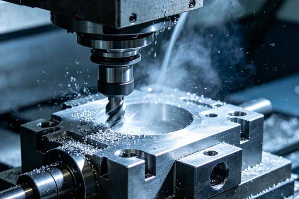
In high-speed CNC milling, chip motion also changes significantly. Chips are ejected at high speed but still maintain continuity. Multi-flute cutting causes chips to pull each other into long chains. Small flute spacing leaves insufficient space for natural fracture. Chip direction changes rapidly with toolpath, making trajectories unstable. Chips are already fully formed before leaving the cutting zone. Chip breaking essentially becomes a problem of controlling chip formation rhythm and trajectory.
Why Does Tool Design Determine Chip Breaking Success?
Many chip breaking issues are already embedded in tool selection.
Geometry Determines Chip Shape
Tool geometry directly affects whether chips will break.
- Large helix angle: smooth evacuation but tends to form long ribbon chips.
- Small helix angle: more likely to create stress concentration and fracture points.
- Sharp cutting edge: lower cutting force but more continuous chips.
- Dull edge: easier chip breaking but higher heat and load.
- Chip breaker grooves: promote fracture by forcing chip curling.
- Nose radius: affects chip curl radius and formation rhythm.
The key is not cutting faster, but making chips break at the right position.
Coating and Friction Effects
In high-speed CNC milling, coatings affect not only tool life but also chip breaking behavior.
- Low-friction coatings reduce resistance, allowing chips to slide out more smoothly.
- Reduced friction can decrease fracture initiation points.
- Highly lubricated coatings may increase long-chip tendency in some materials.
- Heat-resistant coatings reduce sticking but may alter heat distribution and fracture location.
- Multi-layer coatings change chip curl angle, making behavior less predictable.
- Coating wear causes sudden friction changes, leading to unstable chip breaking.
The key is balancing friction, temperature, and chip evacuation.
Hidden Effects of Tool Wear
Tool condition changes are often the early sign of chip breaking failure.
- Dull edges shift cutting from shearing to extrusion, making chips harder to break.
- Local chipping causes uneven cutting forces, leading to unstable chip formation.
- Coating delamination increases friction, promoting chip adhesion and long chains.
- Heat accumulation increases chip residence time on the tool, further elongating chips.
- Tool runout or poor clamping can also cause periodic abnormal chip growth.
Many chip breaking issues are essentially tools operating outside their design condition.
Why Are CNC Milling Parameters So Hard to Balance for Chip Breaking?
Chip breaking and efficiency often conflict naturally.
Conflict Between Feed and Speed
Too low feed produces thin chips that cannot generate fracture stress. Too high feed creates thick chips that wrap around the tool. Excessive spindle speed increases heat and material ductility. Too low speed leads to discontinuous cutting and long chips. The chip breaking window is very narrow and requires fine tuning. Therefore, parameters must be dynamically optimized based on material and tool condition.
Influence of Depth and Width of Cut
Chip formation is affected by multiple interacting factors.
- Small depth of cut: long, continuous chips with little fracture tendency.
- Large depth of cut: higher load but increased evacuation pressure.
- Excessive width of cut: lateral chip expansion forming ribbon structures.
- Uneven width: localized stress concentration and unstable breaking points.
- Interrupted cutting: irregular chip length and unstable rhythm.
Cutting geometry itself “programs” chip behavior.
Hidden Influence of Toolpath
In CNC machining, toolpath design directly affects chip behavior.
- Climb milling: smoother cutting but more continuous chips.
- Conventional milling: stronger impact, easier local chip breaking but higher surface risk.
- Sudden path changes: stretch chips into long strands.
- Long straight paths: stable long chip flow and continuous accumulation.
- Frequent direction changes: disrupt chip rhythm but may cause local buildup.
- High-speed corners: sudden load changes causing both chip breaking and entanglement.
Toolpath essentially “orchestrates chip formation rhythm.”
Why Are Chip Evacuation and Cooling Equally Critical?
Chip breaking is only the first step—the real challenge is evacuation.
Insufficient Chip Evacuation Space
In CNC machining, chip control directly affects stability and final quality.
- Chip accumulation leads to secondary cutting and dimensional inaccuracy.
- Recutting increases tool wear and shortens tool life.
- Long chips may wrap around the spindle or tool holder, causing downtime or safety risks.
- Chips can scratch machined surfaces, significantly worsening roughness.
- Poor evacuation also increases local temperature, further worsening chip breaking.
Successful chip breaking does not equal successful machining—evacuation completes the process.
Cooling Methods Affect Chip Breaking
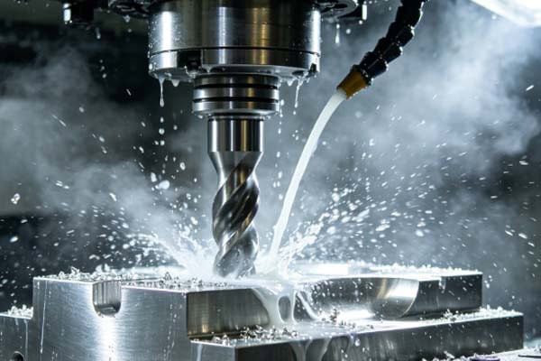
Cooling systems act as hidden regulators in chip breaking. High-pressure coolant promotes fracture by directly impacting the chip root. Air cooling mainly reduces secondary contact but has weaker breaking capability. Lubrication changes friction conditions and may shift fracture locations. Coolant direction affects chip trajectory and curl shape. Flow fluctuations can destabilize chip breaking rhythm. In some cases, the cooling system itself can be considered an auxiliary chip breaking tool.
In high-speed milling, poor chip control is not because the material “cannot be cut,” but because chip formation, curling, and evacuation lose controllability. This is influenced by material plasticity, tool geometry, cutting heat, machining parameters, and chip evacuation design. To improve this issue, the entire CNC milling system must be optimized holistically rather than adjusting a single parameter. Only then can a balance between stable chip breaking and machining efficiency be achieved. If you are struggling with chip breaking and evacuation issues, TiRapid can provide professional high-speed machining optimization and CNC solutions to help improve your process stability.
















