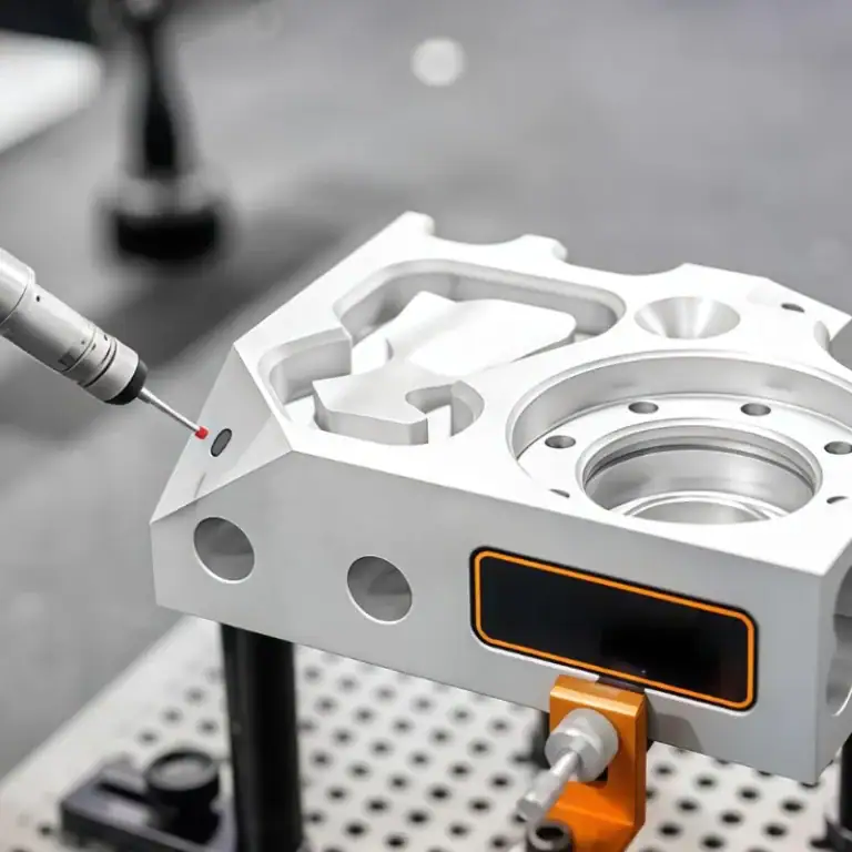
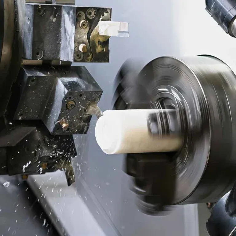
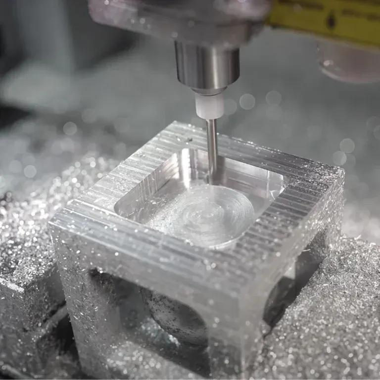
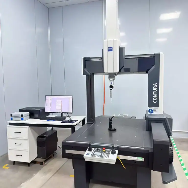
Injection-molded parts follow established design guidelines for uniform wall thickness, but CNC machining is not subject to mold-filling constraints and offers greater design freedom—which is why extremely thin wall designs frequently appear on drawings. However, while CNC machining can theoretically cut very thin features, the practically achievable wall thickness is governed by a combination of material properties, tool diameter, workholding methods, and part geometry. If these limitations are not considered at the design stage, discovering at the machining stage that a wall cannot be produced costs far more in drawing revisions and schedule delays than an upfront assessment would have.
Core Factors That Determine Minimum Wall Thickness
Material Rigidity and Brittleness
Minimum wall thickness is directly linked to the mechanical properties of the material. Brittle materials such as acrylic are prone to fracturing under cutting forces when walls are thin. Even if the tool can physically cut to the designed thickness, vibration or localized stress during machining may cause the wall to crack. Ductile materials such as POM and nylon are less susceptible to brittle fracture, but elastic deformation in thin-wall regions can compromise dimensional accuracy. When assessing minimum wall thickness, it is therefore necessary to consider both whether the material can be cut to the required thickness and whether it can hold its shape after cutting.
Typical performance by material:
Acrylic—highly brittle, thin-wall machining carries significant risk; minimum recommended wall thickness is generally no less than 1.0 mm
PC—tougher than acrylic, but machining stress can cause whitening in thin-wall areas; a minimum of 0.8 mm is recommended
POM—good dimensional stability with balanced rigidity and toughness; walls of 0.5 mm to 0.8 mm are achievable
Nylon—good ductility but relatively soft; thin walls are prone to bending and deformation during machining; a minimum of 1.0 mm is recommended
PEEK—excellent strength and rigidity; walls of 0.5 mm or even thinner are possible, though the high material cost typically leads to more conservative designs
How Wall Height Affects Machining Difficulty
A wall 0.5 mm thick and 5 mm tall is in an entirely different category of difficulty from a wall 0.5 mm thick and 30 mm tall. The greater the wall height, the longer the tool overhang required and the larger the bending moment generated by cutting forces—both of which intensify wall vibration and deformation.
As a rule of thumb: when the wall-thickness-to-wall-height ratio is better than 1:5 (for example, 1 mm thickness with 5 mm height), most engineering plastics can be machined stably under standard parameters. When the ratio approaches 1:10, deformation must be controlled by reducing the depth of cut, optimizing toolpaths, and adding support. At ratios exceeding 1:15, machining difficulty rises sharply and yield rates drop noticeably, at which point the design should be re-evaluated to see whether there is room for optimization.
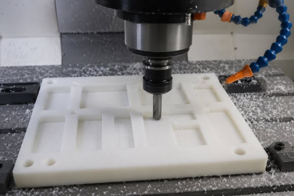
Tooling Constraints on Wall Thickness
Relationship Between Tool Diameter and Minimum Wall Thickness
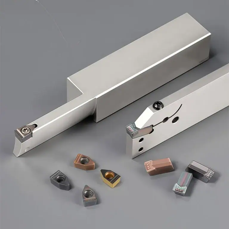
In CNC machining, no structural wall can be thinner than the cutter diameter—this is an absolute physical constraint. However, the practically achievable minimum wall thickness is usually substantially greater than the tool diameter, because thin walls deflect elastically under the lateral cutting forces from the tool, producing a deviation between the actual machined thickness and the programmed value. A smaller-diameter tool can theoretically reach thinner walls, but its inherently lower rigidity makes deflection and vibration problems more pronounced.
Typical correspondence under general conditions:
- 1 mm tool diameter—achievable wall thickness approximately 0.8 mm to 1.2 mm
- 2 mm tool diameter—achievable wall thickness approximately 1.0 mm to 1.5 mm
- 3 mm tool diameter—achievable wall thickness approximately 1.2 mm to 2.0 mm
- 4 mm tool diameter and above—wall thickness is no longer limited by tool diameter
Tool Overhang Length
Thin walls are often associated with confined spaces, requiring the tool to extend in order to reach the machining position. The greater the overhang, the larger the tool deflection under cutting forces, and the harder it becomes to maintain wall-thickness consistency—there may be a noticeable difference between the thickness at the top of the wall and at the root. For long-overhang situations, it is advisable to step up one tool-diameter size (for example, switching from a 2 mm tool to a 3 mm tool), trading some minimum-wall-thickness capability for improved machining stability.
Workholding Considerations for Thin-Wall Machining
Conventional vise clamping introduces concentrated stress near thin-wall features; once the part is released, the wall may distort due to stress relaxation. A vacuum chuck applies no lateral pressure to thin-wall areas and is the more desirable option where applicable, though it requires a flat bottom surface on the part and sufficient adsorption area. Double-sided adhesive tape as a temporary fixture can work well for finishing operations on certain thin-wall parts, but its positioning accuracy and repeatability fall short of mechanical clamping.
For localized thin-wall features, one approach is to leave supporting ribs or connector bridges in place during the main machining sequence and remove them afterward—effectively providing temporary support throughout the cutting process. This technique is widely used for thin-walled shell-type parts, but it requires early communication between the designer and the machinist; if the drawing is released without such provisions, it is difficult for the machine shop to add auxiliary support structures unilaterally.

Common Quality Risks in Thin-Wall Machining
Uneven Wall Thickness
After thin-wall areas are machined, the wall may end up thinner at the top and thicker at the root, or may exhibit a wavy thickness variation along its length. Tool deflection and wall vibration are the primary causes. Improvement measures include reducing the depth of cut per pass, lowering the feed rate, and adopting climb milling to reduce the pushing force exerted by the tool on the wall. If both sides of the wall require finishing, machining one side completely before starting on the other tends to produce more uniform wall thickness than alternating between the two sides.
Chatter Marks on the Surface
During cutting, a thin wall behaves somewhat like a thin plate and can readily be excited into vibration at its natural frequency. Once vibration sets in, periodic chatter marks appear on the wall surface. These marks cannot be removed by polishing—because the pattern results from periodic variation in the wall thickness itself, not from surface roughness. The solution lies in reducing the cutting excitation: lowering spindle speed to move away from the resonance zone, using a sharp tool to minimize cutting forces, and keeping tool overhang as short as possible. Where vibration cannot be avoided entirely, it may be necessary to temporarily fill the back of the wall with a support medium (such as low-melting-point wax or peelable adhesive) and remove it after machining.
Post-Machining Deformation
For fiber-reinforced plastics or materials with significant internal stress, thin walls may undergo slow deformation after machining—the wall may curl inward or splay outward. This occurs because material removal disturbs the internal stress balance within the part. Mitigation measures include: annealing the sheet material before machining to relieve residual stresses; allowing sufficient dwell time between roughing and finishing so that the part undergoes its first round of stress relaxation before the finishing pass; and keeping the finishing allowance within 0.2 mm to minimize the additional stress introduced by the final cut.
Frequently Asked Questions
Can a smaller tool be used to achieve even thinner walls?
In theory, yes, but small-diameter tools come with rigidity problems. A 0.5 mm diameter end mill is far less rigid than a 1 mm tool; with severe deflection, wall thickness actually becomes harder to control, and the risk of tool breakage rises sharply. In practice, tools with diameters of 1 mm to 2 mm are the common choice for thin-wall machining. If wall thickness below 0.5 mm is genuinely required, an alternative process route is usually considered—laser cutting instead of CNC milling, for example.
Can minimum wall thickness vary between different colors or batches of the same material?
Yes, there can be differences. Even for the same grade from the same manufacturer, different colors mean different masterbatch loadings and subtle formulation adjustments, which can alter rigidity, brittleness, and internal stress. Black acrylic is typically slightly more brittle than clear acrylic and carries a marginally higher risk of chipping during thin-wall machining. Different sheet batches may also differ in their heat-treatment history. For thin-wall parts, it is therefore advisable to run a first-article inspection after changing material batches, confirming that wall-thickness consistency and surface quality meet requirements before proceeding with production.
What tolerances should be specified on drawings for thin-wall features?
Tolerances for thin-wall areas should not be set too tight. A commonly used tolerance of +/-0.1 mm can be difficult to hold reliably for wall thicknesses under 1 mm in actual machining, particularly when the wall height exceeds 10 mm. If functional requirements permit, it is advisable to relax thin-wall tolerances to +/-0.15 mm or +/-0.2 mm, or to call out a minimum local wall thickness rather than constraining both upper and lower limits. For wall sections that do not directly participate in assembly, marking the thickness as a reference dimension is also a common practice; it avoids the situation where the machine shop incurs excessive cost and yield loss trying to hold a tolerance that is functionally unimportant.
In conclusion
There is no absolute numerical lower limit for wall thickness in plastic CNC machining. A 0.5 mm POM wall may be produced reliably, while a 1.5 mm acrylic wall may prove problematic in certain geometries. The core variables determining minimum wall thickness are material type, the ratio of wall thickness to wall height, tool accessibility, and the workholding method. Assessing these factors at the design stage is far more cost-effective than discovering, after the drawing has been issued, that a feature cannot be machined. For parts with numerous thin-wall features, a process review with the machine shop before finalizing the drawing is one of the most effective steps for reducing downstream rework.