A shaft must enter its mating bore, a bearing must stay seated, and a cover must locate correctly on its housing. Each function permits some dimensional variation. The engineering task is to define how much variation the assembly can accept, then communicate that requirement clearly enough to manufacture and inspect.
Machining tolerance establishes those limits. Choosing it well helps control fit and interchangeability while keeping machining and inspection effort proportional to the part’s function.
This guide explains tolerance terminology, common drawing formats, standards, and fits. It also shows how manufacturing conditions affect achievable results and why unnecessarily tight requirements can increase cost.
What Is Machining Tolerance?
Machining tolerance is the permitted variation in a machined feature. For a size dimension, it defines the range between the largest and smallest acceptable values. Geometric tolerances separately control characteristics such as form, orientation, position, and profile.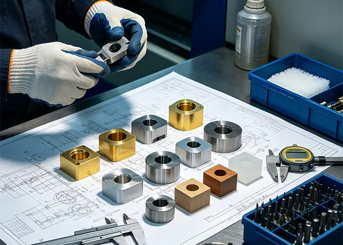
Nominal Size, Limits, And Deviations
The nominal size is the reference dimension used to describe the feature. Upper and lower limits define its permitted size range. Upper and lower deviations express those limits relative to the reference dimension.
A measured deviation describes a particular result relative to its nominal value. It is different from the total tolerance, which describes the width of the allowed range.
In GD&T, a boxed basic dimension has a specific meaning. It defines a theoretically exact value, with allowable variation controlled by the associated geometric requirements. It should not be read as an ordinary dimension governed automatically by the title block’s plus/minus tolerance.
Calculating The Total Tolerance
Consider an illustrative dimension of 20.00 ± 0.05 mm. Its limits are:
- Upper limit: 20.05 mm
- Lower limit: 19.95 mm
- Total tolerance: 20.05 − 19.95 = 0.10 mm
The ±0.05 mm value describes the permitted deviation in each direction. The total tolerance band is 0.10 mm wide.
If the measured size is 20.03 mm, its deviation from nominal is +0.03 mm. That result lies inside the stated dimensional limits.
Tolerance, Accuracy, And Repeatability
Tolerance is a design requirement. In machining, accuracy concerns how closely the produced feature matches its intended value. Repeatability concerns the agreement of repeated results under specified conditions.
A process may produce closely grouped dimensions that are consistently offset from the target. Another may average near the target but vary too widely. Neither behavior can be understood from the tolerance value alone.
For sourcing, ask whether the proposed process can maintain the required characteristics across the order. A machine’s positioning specification is only part of that assessment.
A supplier may aim for a process target inside the permitted band to leave room for expected variation. That target supports production control, while the drawing continues to define the acceptance limits. A result does not have to equal nominal exactly to satisfy the size requirement.
What Are The Main Types Of Machining Tolerances?
Size tolerances can be expressed through bilateral deviations, unilateral deviations, or direct limits. Geometric tolerances describe different requirements, including the shape and spatial relationships of features. Selecting the right format helps communicate the design intent.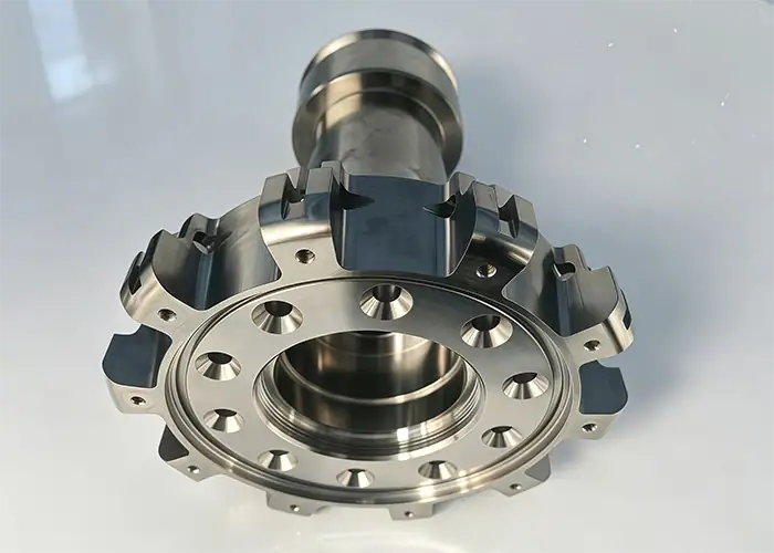
Bilateral And Unilateral Dimensional Tolerances
A bilateral tolerance permits variation on both sides of the nominal size. The deviations may be equal or unequal. Symmetric plus/minus notation is common when the allowable range is centered on the reference value.
A unilateral tolerance permits variation in one direction from the stated size. It can be useful when one limit is particularly important to a design or matches the chosen fit system.
Neither notation automatically determines manufacturing difficulty. Two differently written dimensions can describe the same acceptable limits. Compare those limits before treating one callout as tighter than another.
Limit Dimensions
Limit dimensions state the maximum and minimum acceptable sizes directly. The reader does not need to calculate them from a nominal size and deviations.
The following drawing examples use millimeters and illustrate notation only.
| Drawing Format | Example | Permitted Size Range |
| Bilateral | 20.00 ± 0.05 | 19.95 to 20.05 |
| Unilateral | 20.00 +0.05/−0.00 | 20.00 to 20.05 |
| Direct limits | 19.95 to 20.05 | 19.95 to 20.05 |
The bilateral and direct-limit examples define the same range. The unilateral example has a smaller total range and a different lower limit.
Geometric Tolerances And Datum References
Size alone cannot describe every functional requirement. A bore can have an acceptable diameter while its axis is incorrectly located. A seating face can have an acceptable height while its surface is insufficiently flat.
GD&T provides controls for these characteristics. Flatness evaluates surface form without a datum. Position and perpendicularity can relate features to a specified datum reference frame. Profile controls the permitted variation of a line or surface.
Apply the complete feature control frame, including datum order and any material condition modifiers. A position tolerance cannot be interpreted as a general plus/minus allowance on every coordinate.
What Are Standard CNC Machining Tolerances?
Standard CNC machining tolerances may refer to a drawing’s general tolerance specification or a supplier’s default service requirements. Their application depends on the stated standard, tolerance class, feature size, and agreed order requirements.
General Tolerances And Drawing Notes
General tolerances simplify drawings by covering applicable dimensions without individual tolerance indications. ISO 2768-1:1989 is a reference for general linear and angular tolerances. Its classes and size ranges determine the applicable allowance.
Reading a general tolerance therefore requires more than finding a familiar standard number. Identify the cited edition and class, locate the relevant dimension category and size interval, and check whether a separate requirement applies to the feature.
General size tolerances and general geometric specifications also need to be distinguished. ISO 2768-2:1989 has been withdrawn and superseded by ISO 22081:2021. The newer document uses a different approach to general specifications, so legacy drawing notes should be reviewed rather than changed mechanically.
Follow the product definition agreed for the job. Where an older drawing is still specified, resolve any uncertainty with the responsible engineering team before changing its requirements.
Supplier Defaults And Feature-Specific Requirements
A supplier may state a default tolerance for features without individual callouts. That default can depend on its service route, material, part size, or quoting conditions.
For a critical bearing seat, sealing interface, or locating feature, communicate the required control explicitly. Confirm that the quotation includes it and that inspection can verify it in the required part condition.
| Requirement Source | Typical Role | What To Confirm |
| General drawing note | Covers applicable unspecified dimensions | Standard, edition, class, and scope |
| Individual callout | Defines a particular feature requirement | Limits, datums, modifiers, and finish condition |
| Supplier quotation | Records the accepted manufacturing scope | Included requirements and agreed exceptions |
An individually specified critical dimension can therefore require different control from adjacent features covered by a general note. Applying the tightest callout to the whole part can change the manufacturing scope substantially.
How Do Machining Tolerances Determine Part Fit?
Fit depends on the combined limits of the mating features. Evaluating the smallest and largest possible clearance or interference shows whether the selected dimensions support the intended assembly, movement, or retention.
Clearance, Transition, And Interference Fits
A clearance fit allows space between the shaft and bore. A transition fit can produce clearance or interference depending on the actual mating sizes. An interference fit creates dimensional overlap that must be accommodated during assembly.
Choose the fit from the required function. A freely moving shaft, a removable locating component, and a permanently retained sleeve have different needs. Lubrication, load, assembly method, and operating temperature may also affect the selection.
For an illustrative size-only clearance calculation, assume:
- Bore limits: 20.000 to 20.020 mm
- Shaft limits: 19.970 to 19.990 mm
- Minimum clearance: 20.000 − 19.990 = 0.010 mm
- Maximum clearance: 20.020 − 19.970 = 0.050 mm
The size limits provide positive clearance throughout this example. The design must also address relevant form and alignment requirements.
ISO 286 provides a system for specifying limits and fits. In a designation such as H7/g6, the letters identify tolerance-zone positions relative to the nominal size, and the numbers identify tolerance grades. The actual limits also depend on the nominal size range.
Uppercase letters identify hole tolerance classes, while lowercase letters identify shaft classes. In a hole-basis system, the selected hole zone is retained and the shaft class is varied to obtain the required fit. Specify both mating features when the assembly depends on their combined limits, then check the applicable table for the actual nominal diameter.
Tolerance Stack-Ups And Assembly Requirements
An assembly gap may depend on several dimensions, each of which varies. A worst-case stack-up evaluates their extreme combinations according to how each dimension contributes to the gap.
Consider a separate illustrative axial assembly, with all dimensions in millimeters:
| Stack Element | Nominal Size And Tolerance | Contribution To Gap |
| Housing space | 30.00 ± 0.05 | Adds available space |
| Spacer | 10.00 ± 0.02 | Occupies space |
| Insert | 19.80 ± 0.03 | Occupies space |
The nominal gap is 30.00 − 10.00 − 19.80 = 0.20 mm. The minimum gap is 29.95 − 10.02 − 19.83 = 0.10 mm. The maximum gap is 30.05 − 9.98 − 19.77 = 0.30 mm. This simplified stack assumes fully seated, rigid components under the same reference conditions.
If the required gap is narrower than this range, review the dimensions driving the variation. Changing the locating scheme or reducing the number of contributing dimensions may be preferable to tightening every feature.
Statistical stack-up methods use additional assumptions about process behavior. They should be selected with evidence about variation and the acceptable assembly risk.
What Affects Achievable Machining Tolerance?
Achievable tolerance depends on the material, feature geometry, tooling, workholding, thermal conditions, and complete manufacturing route. A requirement that is straightforward on one feature can be difficult on another with the same nominal size.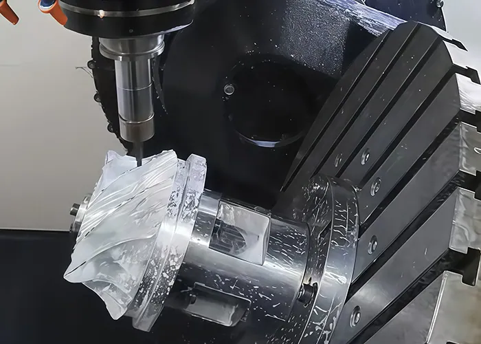
Material And Thermal Behavior
Material stiffness and cutting behavior influence how a part responds during machining. Residual stresses can also cause shape changes as stock is removed, particularly in parts with uneven sections or extensive material removal.
Plastics require attention to thermal expansion, flexibility, and, for moisture-sensitive grades, conditioning. The material grade and inspection condition should be considered together when setting dimensional requirements.
A component measured while warm can change size as it stabilizes. For demanding work, the machining and measurement plans should account for temperature rather than treating every reading as directly comparable.
Feature Geometry, Tooling, And Workholding
Thin walls can deflect under cutting or clamping forces. Deep bores and cavities may require extended tools, making access and rigidity harder to manage. Tool wear and runout can further influence finished size and geometry.
Multiple setups introduce another concern when controlled features are related across different faces. The process must preserve or re-establish the necessary references.
Choose the manufacturing route for the characteristic. A bore may need boring, reaming, or honing after rough machining. Other surfaces may require grinding or a different finishing operation. The choice should follow the required size, form, access, and material.
Surface Treatments And The Final Part Condition
Coatings, plating, anodizing, and other treatments can change controlled dimensions. Their effects depend on the treatment and surface, so the machining allowance and final acceptance condition should be agreed before production.
Identify dimensions that apply after finishing and any surfaces that must be masked or treated differently. A hole checked before coating may no longer represent its delivered condition.
Surface roughness is a separate requirement from size tolerance. When both affect function, specify both and select manufacturing and inspection methods that can address them.
Why Do Tighter Machining Tolerances Cost More?
Tighter tolerances can increase cost by requiring more controlled setups, additional machining operations, closer monitoring, and more demanding inspection. The cost effect depends on the specific feature and process, rather than the tolerance number alone.
Setup, Machining, And Additional Operations
A smaller allowable range may require more preparation to establish a stable process. This can include fixture development, trial cuts, tool presetting, and checks before production is released.
During machining, the supplier may need to manage tool condition more closely or add finishing operations. For some features, meeting a tighter requirement changes the route from ordinary milling or turning to a process with different equipment and setup needs.
Order quantity also matters. Preparation effort is distributed differently across a prototype and a repeat production batch. A useful quotation should reflect the actual quantity and manufacturing plan.
Inspection Effort And Production Risk
Inspection becomes more demanding when the available tolerance is small relative to the measurement uncertainty. Additional setup, environmental control, or specialized measurement may be required.
A narrow acceptance range can also leave less room for process variation. The supplier must consider monitoring, adjustments, and the risk of rework or rejection.
| Requirement Change | Additional Work It May Create | Cost Area Affected |
| Tighter bore size or form | Dedicated finishing and gauging | Setup and machining |
| Tighter datum-related location | More controlled locating and verification | Fixturing and inspection |
| Final size after coating | Coordinated allowances and final checks | Finishing and quality control |
| Individual reports for every part | Additional measurement and record handling | Inspection and documentation |
Concentrate this effort where it supports function. A critical bearing seat and an external relief surface do not necessarily need the same level of control.
When comparing quotations, check that the suppliers priced the same final condition and verification scope. A lower machining price may exclude a finishing operation or inspection record required by the drawing. Clarifying these items makes the comparison more useful than comparing a headline unit price alone.
How Do You Choose And Specify The Right Machining Tolerance?
Start with function and mating requirements, evaluate the assembly variation, and then confirm a practical manufacturing and inspection route. Put critical controls on the drawing and use suitable general requirements for the remaining features.
Start With Functional And Mating Requirements
Identify what each controlled feature must accomplish. Does it locate another component, maintain a running clearance, retain a bearing, or support a seal? Use the answer to determine which variations matter.
Check the mating component’s limits and the relevant stack-up. Include operating conditions when they can change the fit or alignment.
Also review whether the feature is dimensioned from the reference that matters in assembly. Directly controlling a functional distance can reduce dependence on intermediate dimensions. This can make the requirement easier to manufacture and verify without changing the permitted assembly variation.
For noncritical features, choose requirements that provide enough room for economical manufacturing while preserving the intended function. Relaxing a tolerance should follow engineering review of its consequences.
Specify Datums, Critical Features, And Inspection
Use dimensions and geometric controls that express the functional relationships. Establish the necessary datums and avoid adding overlapping requirements that are difficult to interpret together.
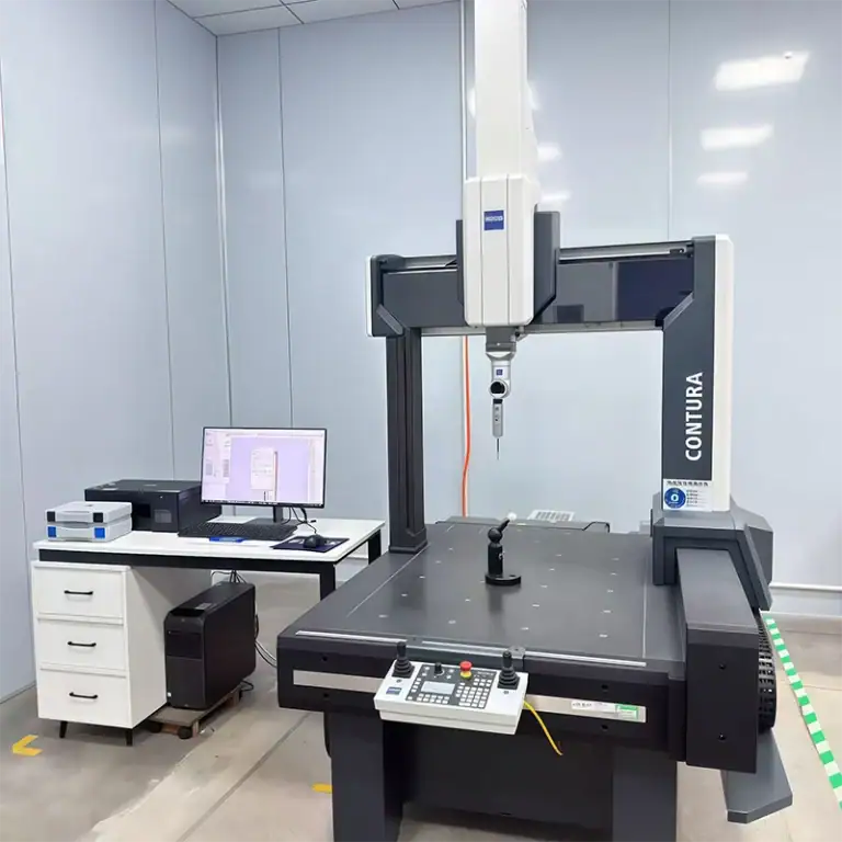
Confirm how each critical characteristic will be checked. A micrometer may suit an accessible size, while datum-related position or profile may need coordinate measurement. Surface texture and thread function need their own appropriate methods.
For tight or borderline results, agree on the measurement approach and conformity decision rule. Instrument resolution alone does not establish whether the method is suitable.
State the required part condition, sampling scope, and reporting needs. These decisions belong in the project requirements early enough to influence the process plan.
Prepare A Clear RFQ For TiRapid
Send TiRapid the current drawing and matching CAD model, together with the material, surface treatment, quantity, and delivery requirements.
Identify critical interfaces and any inspection documents needed with the shipment. If a tolerance is still under review, describe the functional requirement so the discussion can address the part’s actual needs.
Before ordering, confirm the accepted tolerances and any proposed exceptions in writing. This gives engineering, manufacturing, and purchasing a consistent basis for evaluating the quotation and accepting the delivered parts.
FAQs
Do More Decimal Places Always Mean A Tighter Tolerance?
No. Decimal places can determine a default tolerance when the drawing’s title block explicitly links them. Otherwise, the stated limits, general notes, and applicable standards define the requirement. Extra zeros alone do not establish a smaller tolerance band.
Is Surface Roughness The Same As Machining Tolerance?
No. Roughness describes surface texture, while size and geometric tolerances control other characteristics. A smooth surface can still be the wrong size or position. Specify the requirements needed for the feature’s function separately.
Can A Supplier Change A Specified Tolerance Without Approval?
A proposed change should be reviewed and approved by the responsible customer or design authority before manufacture. The revised requirement should be reflected in the agreed drawing, order, or controlled deviation record.
Conclusion
Machining tolerance translates functional requirements into measurable limits. Effective selection connects feature size and geometry with mating parts, assembly variation, manufacturing conditions, and inspection. Tight control is most useful where it protects a specific function.
TiRapid provides precision 3-axis and 5-axis CNC machining for complex metal and engineering plastic parts. We review critical tolerances, material requirements, and inspection needs to develop practical manufacturing plans for prototypes and low-volume production. Send us your drawings, CAD model, and project requirements for manufacturing feedback and a tailored quotation.