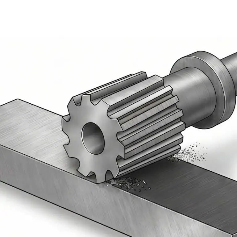
A machined housing can have correctly sized holes and still fail to assemble if those holes are in the wrong locations. Checking each diameter tells you only part of the story. You also need to know how the features relate to the mounting face, locating surfaces, and mating components.
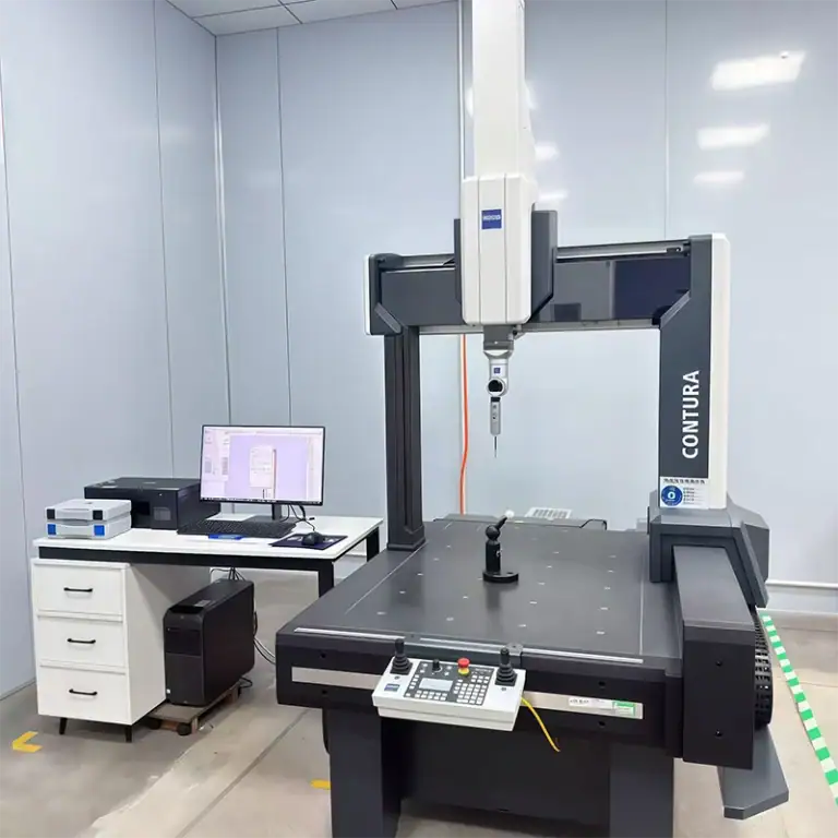
CMM inspection provides that dimensional evidence. A coordinate measuring machine collects surface coordinates, and measurement software uses them to evaluate specified dimensions and geometric requirements. The results help engineers investigate variation and give buyers a documented basis for accepting machined parts.
This guide explains what the process measures, how it works, and how to decide whether the resulting report answers your project’s quality requirements.
What Is CMM Inspection?
CMM inspection uses a coordinate measuring machine to measure part geometry and evaluate it against drawings, CAD definitions, and specified tolerances. It connects physical measurements with the dimensional requirements that govern fit and assembly.
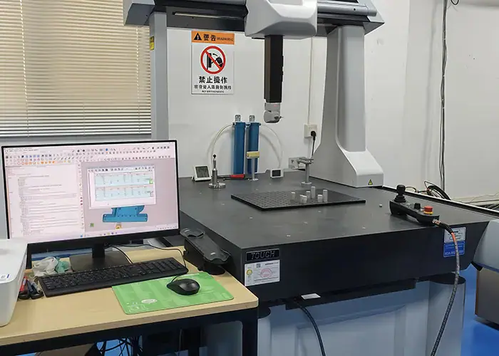
From Surface Coordinates To Measured Features
A CMM records surface locations within a coordinate system. Software combines those points to calculate features such as planes, circles, cylinders, and their relationships. Measuring a bore, for example, can provide information about its diameter and axis.
The software then evaluates the requested characteristic. A diameter result answers a size question. A position result answers a different question about where the feature lies relative to its specified references.
Inspection therefore involves both measurement and interpretation. The drawing defines the requirement, while the measurement plan determines how the physical feature will be sampled and evaluated.
Touch Probing, Scanning, And Optical Measurement
Touch-trigger probes collect individual points as the stylus contacts the surface. Tactile scanning probes gather data along a path, providing broader coverage when a feature needs more detailed evaluation.
Some systems also use optical sensors to collect data without contact. These can be useful for features that are difficult to touch. Line of sight, surface reflectivity, and the sensor’s measurement capability affect suitability.
The choice depends on the inspection task. Measuring an accessible bore and comparing a broad freeform surface may call for different sensors and sampling strategies.
What Can CMM Inspection Verify On CNC Parts?
CMM inspection can evaluate accessible dimensions, geometric tolerances, and surface profiles. The inspection plan must connect each result to the correct drawing characteristic, reference system, and acceptance requirement.
Dimensions And Feature Sizes
Common checks include diameters, widths, step heights, depths, and distances between features. On a machined housing, these may determine whether a bearing fits, a cover seats correctly, or a fastener passes through its mounting hole.
The feature definition matters. A bore diameter calculated from sampled points must represent the size characteristic required by the drawing. A single fitted value may need additional evaluation when the requirement concerns local size or the mating boundary.
For example, a bore with form variation can produce a fitted diameter near its nominal value while behaving differently during assembly. The inspection plan should address the specified size and form requirements so the reported value answers the engineering question.
Geometric Tolerances And Datum Relationships
Geometric dimensioning and tolerancing, or GD&T, controls characteristics that individual size measurements cannot fully describe. Flatness concerns the form of a surface. Perpendicularity and position relate features to specified datums.
A datum is a theoretically exact reference established from a physical datum feature. Depending on the drawing, a mounting face may establish orientation, while other features locate the part within its reference frame.
For a mounting plate, correctly sized holes can still be displaced relative to the locating features. Evaluating their position addresses that spatial relationship. Flatness, by contrast, does not require a datum reference.
Material condition modifiers can affect the allowed geometric tolerance or how a datum is established. The evaluation must follow the complete feature control frame, including any permitted bonus tolerance, rather than using only the displayed geometric tolerance value.
Profiles And Complex Surfaces
For curved geometry, measured points or scan data can be compared with the nominal CAD surface. A deviation map helps reveal where the manufactured surface lies above or below the reference geometry.
The alignment must match the purpose of the comparison. An overall best-fit display can help investigate shape, while a drawing-based profile evaluation must respect its applicable datum and tolerance requirements.
| Drawing Requirement | Example CNC Feature | Inspection Focus |
| Diameter tolerance | Bearing bore | Specified size characteristic |
| Position tolerance | Mounting-hole pattern | Location and orientation within the required tolerance zone |
| Flatness tolerance | Cover seating face | Surface form across the evaluated area |
| Surface profile tolerance | Contoured housing | Surface variation under the specified alignment |
How Is CMM Inspection Carried Out?
The workflow starts by reviewing the product definition, preparing the part and measuring system, and establishing the required alignment. The operator then collects feature data and evaluates the results using the approved inspection program.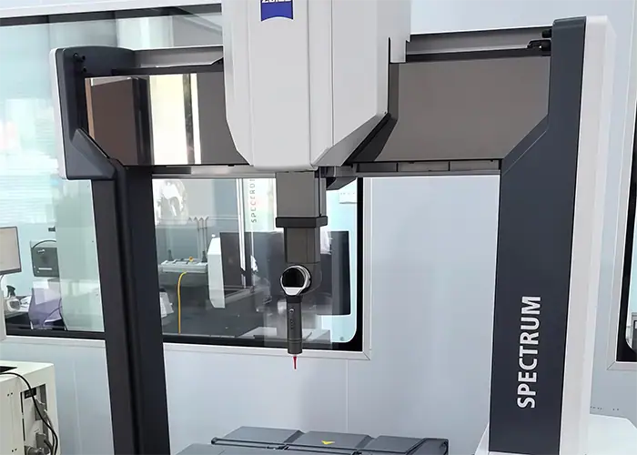
Review The Drawing And Inspection Requirements
Start with the current drawing and model. Check the part number, revision, units, and applicable tolerances. Resolve conflicts between the model and drawing before creating the measurement routine.
Identify the features requiring inspection and the condition in which they must be checked. A final dimension affected by coating may need verification after finishing, while an intermediate measurement may help control machining.
Agree on the number of parts and characteristics to inspect. A report covering selected critical features and a full dimensional layout are different deliverables, with different programming and measurement requirements.
Prepare The Part And Measurement System
Remove contamination that could interfere with contact. Chips, oil films, and loose particles can distort readings. Burrs also need attention, following the specified edge condition rather than removing material from a controlled feature.
Allow the part to stabilize in the measurement environment. A component arriving directly from machining may be at a different temperature from the machine and fixture.
Check the system’s calibration status and complete the required probe qualification. Qualification establishes the characteristics of the stylus configuration used by the program. It does not replace verification of the CMM’s measuring performance.
Fixture The Part And Establish Datum Alignment
Support the component so it remains stable without distorting under clamping or probing forces. Keep datum features and inspection surfaces accessible to the selected stylus.
The physical fixture holds the part, while alignment establishes the mathematical reference frame. A component does not have to sit square to the machine axes to be measured correctly.
Measure the required datum features and establish their prescribed order and constraints. Substituting a convenient surface can change the result, particularly for position and profile requirements tied to the assembly references.
Measure Features And Evaluate Conformance
The program defines probe approaches, clearances, measurement locations, and evaluation settings. An initial prove-out checks access and motion before the routine is used for repeated inspection. If the part must be repositioned, the plan also needs a reliable way to preserve or re-establish the required references.
Collect the data specified by the measurement strategy, preserving the program and setup information needed to interpret it later.
After measurement, review unexpected values, missed contacts, or abnormal scan behavior. Software-generated acceptance results depend on correct input definitions and evaluation settings. A valid routine makes the result traceable to the requirement being checked.
What Makes CMM Inspection Results Reliable?
Reliable results require a suitable measurement system and a controlled method. Calibration, thermal conditions, part restraint, probe configuration, sampling, and evaluation settings all influence confidence in the reported value.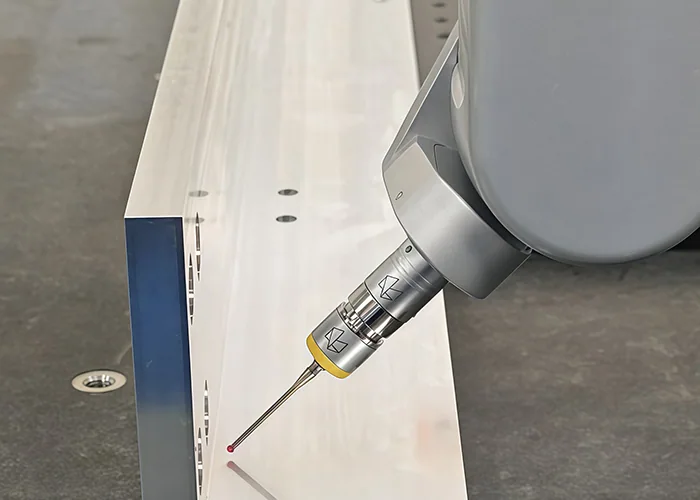
Calibration, Temperature, And Part Stability
Calibration and periodic verification help establish whether the machine remains suitable for its intended work. Checks made during routine use can reveal changes between scheduled services.
Review what the calibration evidence actually covers, including the tested configuration and conditions. A certificate supports assessment of the measuring system. The inspection task still needs suitable probe access, fixturing, and evaluation methods for the particular part.
Temperature affects the measuring system and workpiece. Material expansion, temperature gradients, and handling can influence results, especially when the available tolerance is small. The inspection environment should suit the equipment and measurement task.
Part stability includes its mechanical condition. A thin wall clamped during inspection may appear acceptable while restrained and change shape after release. The setup should represent the required inspection condition, including any specified restraint.
Probe Access, Sampling, And Evaluation Settings
A long stylus may reach a deep feature but introduce different behavior from a shorter configuration. Stylus diameter also affects access and which surface details can be contacted. Select and qualify the configuration for the actual task.
Sampling should reflect expected variation. Points concentrated in an easy-to-reach area can miss taper, lobing, or local distortion. Scanning may improve coverage, but the path and evaluation still need to match the feature.
Fitting and filtering settings also influence calculated results. When two inspection systems disagree, compare their alignment, sampling, and evaluation methods before concluding that the part has changed.
Measurement Uncertainty And Acceptance Decisions
Measurement uncertainty describes the doubt associated with a result. It depends on the particular measurement, including the machine, sensor, setup, part, and environment.
Resolution is the smallest displayed increment. Repeatability describes agreement when measurements are repeated under specified conditions. Neither alone establishes how closely the reported value represents the characteristic being evaluated.
When a result approaches a tolerance boundary, use the agreed acceptance rule and relevant uncertainty information. Extra decimal places do not settle a borderline result. Reviewing the method or using a more suitable measurement approach may be necessary.
How Do You Read A CMM Inspection Report?
Read the report by confirming the part identity and inspection coverage, then matching each result to the drawing requirement. Review nominal values, measured results, tolerances, and acceptance status together.
Check Part Identification And Inspection Coverage
Confirm the part number, drawing revision, units, inspection date, and relevant batch or serial identification. The records should make it possible to establish which physical parts were measured.
Next, connect report entries with drawing characteristics. A ballooned drawing assigns identifiers to requirements, making it easier to find the corresponding result.
Check coverage explicitly. A CMM report may document selected features on selected parts. Its title alone does not establish that every drawing requirement or every component in the shipment was inspected.
Interpret Nominal Values, Deviations, And Tolerances
For a simple dimension, the nominal value is the specified target. The measured result is compared with the permitted limits, and deviation commonly shows measured minus nominal.
Geometric characteristics use different evaluation logic. Flatness, for example, is compared with its allowed form tolerance rather than interpreted as a signed size deviation. Position and profile must be evaluated using their complete tolerance definitions.
The following fictional entries illustrate report reading. All values are in millimeters, and the status column shows a direct comparison with the stated limits.
| Characteristic | Drawing Requirement | Measured Result | Comparison | Status |
| Step height | 10.00 ± 0.05 | 10.02 | +0.02 from nominal | Within stated limits |
| Bore diameter | 20.00 to 20.02 | 20.03 | 0.01 above upper limit | Outside stated limits |
| Flatness | Maximum 0.03 | 0.02 | 0.01 below limit | Within stated limits |
Use the report’s definitions when interpreting abbreviations, graphics, or color indicators. An acceptance flag should be understandable from the stated requirement and result.
For a borderline production result, interpret the comparison using the decision rule discussed earlier. A signed size deviation, a geometric tolerance result, and a color-map distance describe different quantities and should retain their own labels.
Review Out-Of-Tolerance And Borderline Results
First confirm which characteristic is affected and which parts it represents. Then verify the drawing interpretation, setup, and measurement data.
Once the result is established, engineering and quality teams can assess the cause and determine the authorized disposition. Measurement provides evidence for that decision. It does not authorize changing the tolerance or accepting a deviation.
If repeat measurements disagree, investigate the difference and retain the relevant records. Repeating the measurement until an acceptable reading appears obscures the actual issue.
When Should CMM Inspection Be Used In Production?
Use CMM inspection when the geometry, tolerance relationships, or documentation requirements justify it. Place checks at stages where the results can guide production decisions or support the agreed release requirements.
First Article And Process Change Verification
An initial inspection can verify the output of a new program or setup before production continues. A housing’s bore alignment or a plate’s hole pattern may reveal issues that basic size checks would miss.
Changes to the design, fixture, toolpath, or manufacturing route may require verification of affected characteristics. The scope should follow the change and the customer’s requirements.
Record the results against the inspected component and the manufacturing revision being evaluated. This establishes a reference for subsequent checks after an approved change.
In-Process Checks And Final Inspection
Intermediate checks are useful when a result can influence a subsequent operation. For example, verifying critical bore locations before an expensive finishing operation can identify a dimensional problem before more value is added to the part.
Measurements collected consistently across production can also support investigation of trends. Tool wear, setup changes, and thermal effects are possible causes to investigate rather than conclusions proved by a single report.
Final inspection verifies the agreed characteristics in the required delivery condition. The inspection plan should state whether the scope is sampling or every part, and how individual results connect to the shipment.
Choosing CMM And Complementary Inspection Methods
Use the method that can evaluate the requirement with suitable confidence and effort. Accessible thicknesses or outside diameters may be checked efficiently with micrometers. Dedicated gauges can support repeated production checks.
CMMs are useful when spatial relationships, multiple datums, or complex geometry need evaluation. Other requirements need appropriate sensors or separate methods.
| Inspection Need | Suitable Approach | Main Consideration |
| Accessible size dimension | Micrometer or suitable gauge | Range, access, and measurement capability |
| Datum-related position or profile | CMM with a suitable measurement plan | Alignment, sampling, and uncertainty |
| Thread functional acceptance | Appropriate thread gauge | Specified thread and gauging requirement |
| Surface roughness | Surface texture instrument or dedicated CMM sensor | Ordinary dimensional probing does not establish roughness |
| Cracks or internal discontinuities | Appropriate nondestructive testing method | Material and defect type determine the method |
How Should You Specify CMM Inspection For A CNC Order?
Specify the features, part condition, inspection quantity, and documentation you need when requesting a quotation. These details let the supplier plan measurement alongside machining and finishing.
Provide Drawings, Datums, And Critical Features
Send a controlled drawing and the corresponding CAD model. Identify the tolerances and interfaces that govern assembly or performance, especially requirements that are easy to misinterpret.
Explain any inspection conditions that matter. A flexible component may need a defined support arrangement. A coated feature may need a final acceptance check after finishing.
Identify cosmetic or sensitive surfaces that require careful handling. This allows the supplier to consider contact locations and support methods while reviewing access to the controlled features.
Discuss hard-to-reach surfaces during drawing review. Probe access, surface visibility, and the required characteristic can affect the inspection route. Resolving these points early prevents an inaccessible feature from becoming a delivery-stage dispute.
Agree On Sampling, Reports, And Delivery Records
Define the characteristics and number of parts to measure, along with the required report format. State whether you need a ballooned drawing, dimensional results, individual part identification, or a formal first article submission.
Also agree on how nonconforming results will be communicated and which records must accompany delivery. Retaining the inspection program revision and relevant setup information can help investigate later questions.
A useful request might ask for measured results for every identified critical characteristic, linked to the inspected part, plus an agreed sampling plan for the remaining dimensions. This is easier to quote and verify than a general instruction to provide a quality report.
For a TiRapid quotation, include these inspection requirements with your model, drawing, material, finish, and order quantity. This gives the project team the information needed to discuss manufacturing and verification as part of the same order.
FAQs
How Long Does CMM Inspection Take?
Time depends on feature count, access, setup, programming, and reporting requirements. A new complex part needs different preparation from a repeat order with a validated routine. Request an estimate based on the drawing and inspection scope.
Can CMM Inspection Be Used For Plastic Parts?
Yes. The method must account for flexibility, temperature, and possible deformation under contact or clamping forces. Suitable support, controlled probing, or an appropriate optical sensor may be needed for the feature being checked.
Is A CMM Report The Same As A First Article Inspection Report?
No. A CMM report documents measurements within its stated scope. A first article inspection report can include those results alongside material, process, and other required verification records. Its required content follows the customer’s specification and applicable requirements.
Conclusion
CMM inspection verifies CNC part dimensions and geometry by connecting measured features with defined drawing requirements. Useful results depend on the correct alignment, suitable sampling, controlled conditions, and a report that identifies what was actually inspected.
Send TiRapid your drawing, CAD model, and key inspection requirements when requesting a quotation. Defining critical features and delivery records early gives the machining and quality teams a clear basis for planning your project.