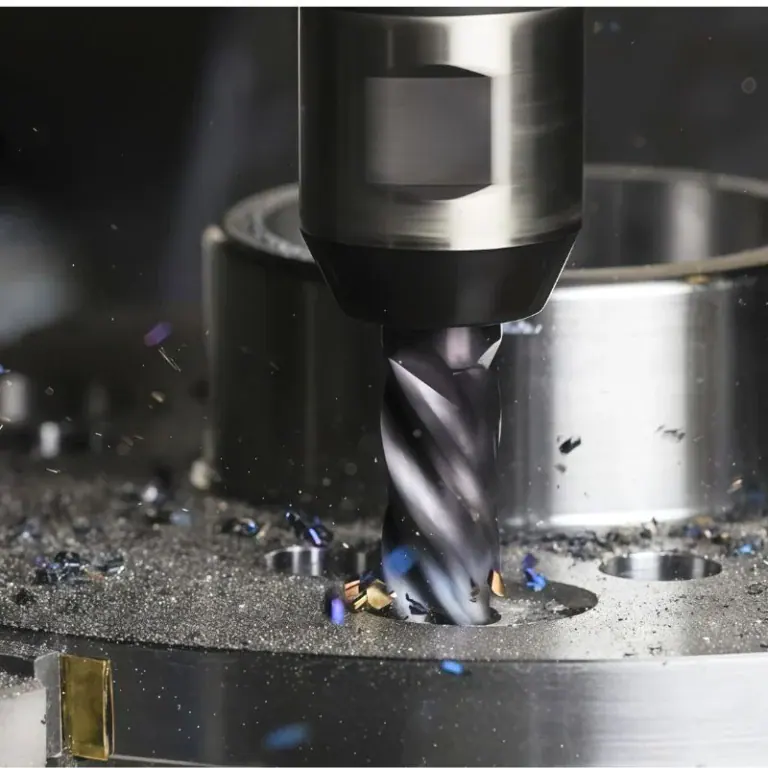
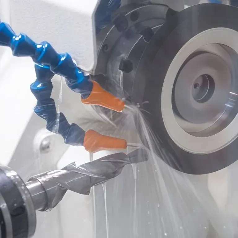
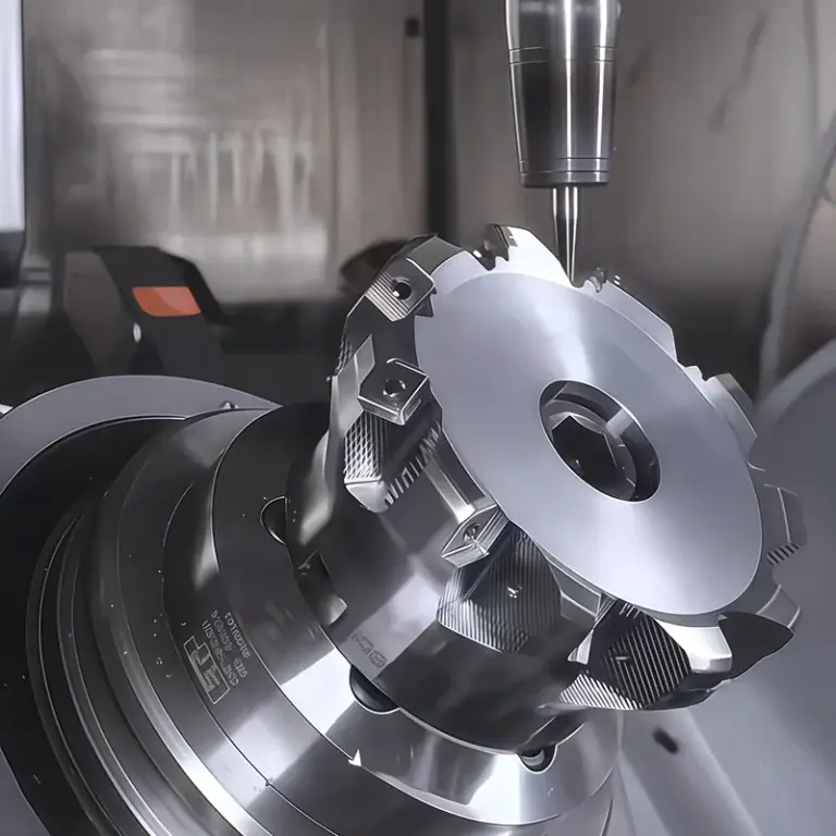
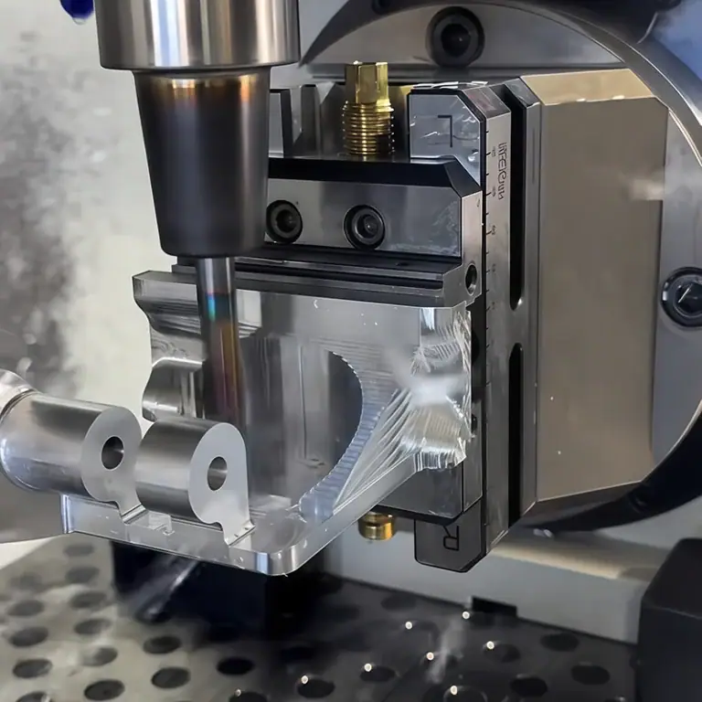
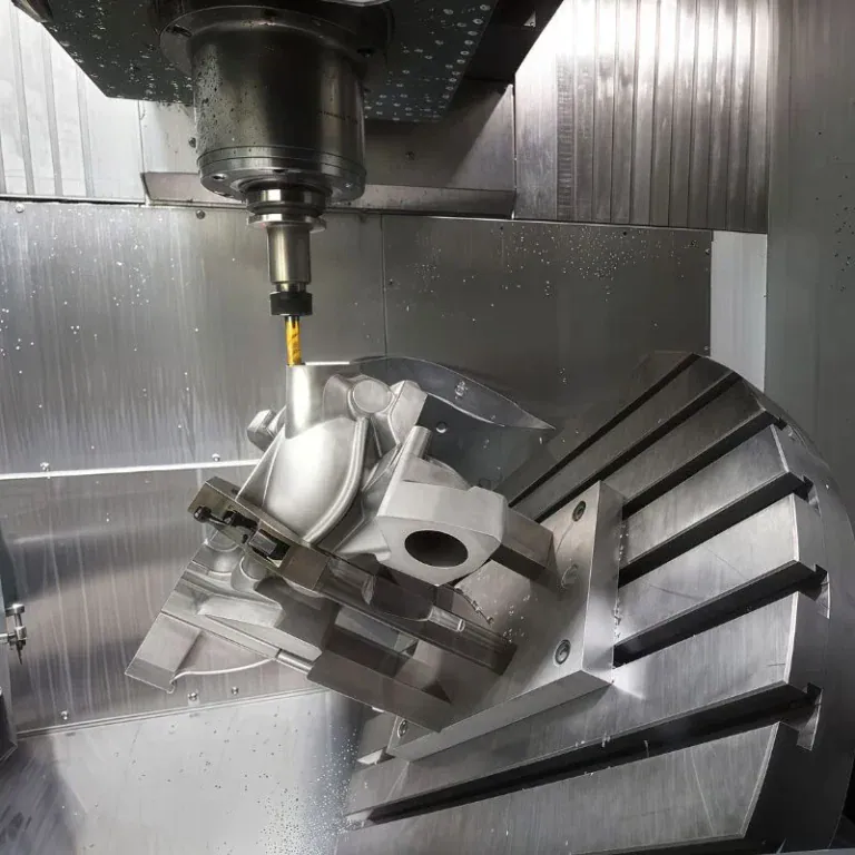
SFM machining uses surface feet per minute to measure the cutting speed between a rotating tool and the workpiece. It helps machinists calculate suitable spindle speeds, control cutting conditions, and balance material removal with tool life. Understanding SFM is essential when machining aluminum, steel, stainless steel, titanium, and other engineering materials on CNC milling machines and lathes.
This guide explains SFM machining, including its meaning, calculation formulas, SFM-to-RPM conversion, material-specific cutting speeds, and applications in CNC milling and turning.
What Is SFM in Machining?
SFM in machining stands for Surface Feet per Minute, a measurement of cutting speed expressed in feet per minute. It describes the relative surface speed between the cutting edge and workpiece. SFM is used to calculate spindle RPM, select suitable cutting parameters, and balance machining productivity with tool life and surface finish.
Definition and Meaning of SFM
The sfm meaning is Surface Feet per Minute, a unit that expresses the tangential cutting speed at the contact between a rotating cutting edge and the workpiece. It represents linear surface movement rather than the number of spindle revolutions.
For example, a 1-inch-diameter cutter travels a greater circumferential distance during one revolution than a 0.5-inch cutter. At the same RPM, the larger cutter therefore produces twice the peripheral surface speed. This distinction is important when changing cutter sizes or transferring machining parameters between jobs.
SFM Measurement Units and Metric Conversion
SFM is measured in feet per minute and is commonly used in imperial CNC machining calculations. In metric manufacturing, cutting speed is normally expressed in meters per minute, written as m/min.
The conversion is:
- 1 SFM = 0.3048 m/min
- 1 SFM = 304.8 mm/min
- 100 SFM = 30.48 m/min
- 300 m/min ≈ 984.25 SFM
Although millimeters per minute can express linear speed, machining references generally use meters per minute for cutting speed. Millimeters per minute is more commonly used for linear feed rate. These quantities must not be confused when preparing CNC programs.
SFM vs. RPM: What Is the Difference?
SFM measures cutting surface speed, while RPM measures the number of revolutions completed by the spindle each minute. They describe different aspects of tool movement and cannot be used interchangeably.
| Parameter | SFM | RPM |
| Full Name | Surface Feet per Minute | Revolutions per Minute |
| Measures | Linear cutting speed | Rotational speed |
| Unit | ft/min | rev/min |
| Depends On | Diameter and RPM | Programmed spindle rotation |
| Main Purpose | Select cutting conditions | Set spindle operation |
The relationship between sfm vs rpm becomes clear when cutter diameter changes. A smaller cutter requires higher RPM to maintain the same SFM, while a larger cutter requires lower RPM. This principle is fundamental to cutting-speed calculations.
Why Is SFM Important in CNC Machining?
SFM is important in CNC machining because it helps establish suitable cutting conditions for different materials and cutting tools. Correct surface speed supports predictable tool life, stable chip formation, controlled heat generation, and efficient material removal. Incorrect SFM can accelerate tool wear, reduce productivity, and contribute to poor surface quality.
How SFM Affects Tool Life and Wear
SFM affects tool life by influencing cutting temperature, friction, and the rate at which the cutting edge experiences mechanical and thermal loading. For a given tool and material, excessive cutting speed can accelerate wear and reduce cutting-edge stability.
Carbide tools typically tolerate higher cutting speeds than high-speed steel tools, although their performance also depends on coating, geometry, and cutting conditions. Excessive heat may cause rapid flank wear, crater wear, coating damage, or edge failure.
Selecting a suitable SFM allows the cutting edge to operate within its intended performance range. The goal is not maximum tool life at any cost, but an economical balance between tool consumption, machining time, and finished part quality.
How SFM Influences Surface Finish and Accuracy
SFM influences surface finish through cutting temperature, built-up edge formation, tool wear, and cutting stability. A suitable speed can support more consistent chip formation and reduce surface defects associated with unstable machining.
For example, when machining aluminum, unsuitable cutting conditions may encourage material adhesion to the cutting edge. In stainless steel, excessive heat and tool wear may produce inconsistent surface texture or dimensional drift during longer operations.
However, SFM alone cannot guarantee machining accuracy. Tool runout, feed per tooth, workholding, machine rigidity, and thermal conditions must also be controlled. A smooth surface does not necessarily mean a part meets its dimensional or geometric tolerances.
How SFM Affects Machining Efficiency and Cost
SFM influences machining cost because cutting speed affects the attainable spindle RPM, tool wear, and achievable production rate. Increasing SFM may reduce cycle time when the process remains stable, but excessive speed can increase tool replacement and scrap costs.
A lower SFM may protect tools in difficult materials, yet overly conservative settings can extend production time. For large production batches, even small changes in tool life or cycle time can affect total manufacturing cost.
Efficient machining therefore requires balancing cutting speed with feed rate, cutter engagement, tool life, and machine utilization. The most economical setting is the one that consistently produces acceptable parts at a practical total cost.
How to Calculate SFM and RPM in Machining
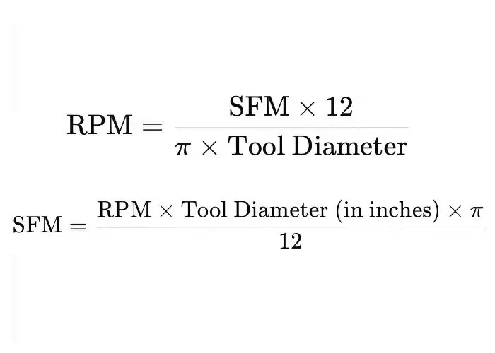
SFM and RPM are calculated from the cutting diameter and rotational speed. The standard imperial formulas are SFM = (π × D × RPM) ÷ 12 and RPM = (12 × SFM) ÷ (π × D), where D is measured in inches. These equations allow machinists to convert between surface cutting speed and spindle speed for CNC milling and turning.
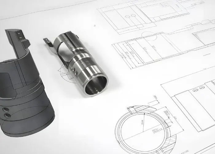
The calculation should begin with the diameter at which cutting occurs. For conventional peripheral milling, this is generally the effective cutter diameter. For turning, it is the workpiece diameter at the current cutting location.
The resulting RPM must then be checked against machine spindle limits, cutter specifications, workholding capability, and the planned machining operation. A mathematically correct spindle speed is not automatically a safe or practical machining setting.
SFM Formula and Key Variables
The standard sfm formula is:
SFM = (π × D × RPM) ÷ 12
Where:
- SFM = Surface Feet per Minute
- D = Effective cutting diameter in inches
- RPM = Spindle revolutions per minute
- π = Approximately 3.1416
- 12 = Inches per foot
The diameter and RPM must refer to the same rotating cutting geometry. In milling, the rotating cutter creates the cutting speed. In turning, the rotating workpiece creates the surface movement relative to the cutting tool.
For metric calculations, the equivalent cutting-speed formula is:
Vc = (π × D × RPM) ÷ 1,000
Where Vc is cutting speed in m/min, D is the effective diameter in millimeters, and RPM is spindle speed in revolutions per minute.
How to Convert SFM to RPM
To convert sfm to rpm, multiply the required surface speed by 12 and divide by π times the cutting diameter in inches.
RPM = (12 × SFM) ÷ (π × D)
A simplified rpm formula is:
RPM ≈ (3.82 × SFM) ÷ D
For example, suppose a 0.5-inch cutter is intended to operate at 300 SFM.
Calculation:
RPM ≈ (3.82 × 300) ÷ 0.5
RPM ≈ 1,146 ÷ 0.5
RPM ≈ 2,292 RPM
The calculated spindle speed is approximately 2,292 RPM. This is an arithmetic example, not a universal recommendation for a particular material.
How to Convert RPM to SFM
Converting RPM to SFM allows machinists to check the cutting speed produced by an existing spindle setting.
The formula is:
SFM = (π × D × RPM) ÷ 12
Suppose a CNC milling machine runs a 0.5-inch cutter at 2,300 RPM.
Calculation:
SFM = (3.1416 × 0.5 × 2,300) ÷ 12
SFM = 3,612.84 ÷ 12
SFM ≈ 301.07 ft/min
The cutting speed is approximately 301 SFM.
This conversion is useful when a CNC program already contains spindle RPM but the machinist needs to verify whether the cutting speed is appropriate for a different tool or material.
SFM Calculation Examples for CNC Machining
Consider a 0.25-inch carbide end mill machining 6061 aluminum at an illustrative cutting speed of 800 SFM.
First, calculate spindle RPM:
RPM ≈ (3.82 × SFM) ÷ D
RPM ≈ (3.82 × 800) ÷ 0.25
RPM ≈ 3,056 ÷ 0.25
RPM ≈ 12,224 RPM
Next, calculate feed rate.
If the cutter has three effective teeth and the selected chip load is 0.0025 inch per tooth, the feed rate formula is:
Feed Rate (IPM) = RPM × Number of Teeth × Feed per Tooth
F = 12,224 × 3 × 0.0025
F = 91.68 IPM
Feed Rate ≈ 91.7 IPM
The calculated spindle speed is approximately 12,224 RPM, and the programmed feed is approximately 91.7 inches per minute.
| Variable | Example Value |
| Workpiece Material | 6061 Aluminum |
| Cutter Diameter | 0.25 in |
| Selected SFM | 800 |
| Calculated Spindle Speed | 12,224 RPM |
| Effective Cutting Teeth | 3 |
| Chip Load | 0.0025 in/tooth |
| Calculated Feed Rate | 91.7 IPM |
This example demonstrates the relationship between SFM, RPM, and feed rate. Actual production settings must be selected from tool-specific cutting data and adjusted for machine limits, engagement, and rigidity.
What Factors Affect SFM Selection?
SFM selection depends on workpiece material, hardness, cutting tool material, coating, geometry, machine rigidity, spindle speed limits, feed rate, depth of cut, and cooling conditions. These factors determine whether the selected cutting speed can produce stable chips, acceptable tool life, and consistent part quality.
Material and tool characteristics establish the initial cutting-speed range, while machine and process conditions determine whether that range is practical.
For example, a carbide end mill cutting aluminum may operate at a much higher surface speed than a high-speed steel tool cutting stainless steel. Even within the same material, slotting and light finishing may require different settings.
Workpiece Material and Hardness
Workpiece material affects SFM because hardness, thermal conductivity, toughness, and chemical interaction influence cutting forces and tool wear. Different alloys require different cutting-speed recommendations.
Aluminum alloys generally allow higher cutting speeds with suitable carbide tools. Stainless steels may generate greater heat and promote adhesion or work hardening, while titanium alloys often require more conservative cutting speeds because of their thermal and mechanical behavior.
Hardness must also be considered. Annealed and hardened versions of the same steel can require significantly different cutting conditions. Material grade, heat-treatment state, and tool manufacturer guidance should be checked before selecting SFM.
Cutting Tool Material, Coating, and Geometry
Cutting tool material affects the cutting speeds a tool can withstand. Carbide cutting tools commonly support higher SFM than high-speed steel, while advanced coatings may improve heat resistance, wear behavior, or chip flow for suitable applications.
Tool geometry also changes cutting performance. Sharp aluminum-specific cutters may reduce adhesion, while stronger cutting edges may be preferred for difficult alloys. Flute count affects chip evacuation and the feed rate calculation.
Coatings should match the workpiece material. No single coating performs best across aluminum, stainless steel, hardened steel, and titanium. Tool-specific specifications provide a more reliable starting point than a general-purpose material chart.
Machine Rigidity and Spindle Speed Limits
Machine rigidity influences whether a selected SFM can be used without excessive vibration or deflection. A rigid machining center with stable fixturing can often support more demanding cutting conditions than a less stable setup.
Spindle speed limits are particularly important for small tools. Because RPM increases as cutter diameter decreases, a high SFM recommendation may exceed the available spindle speed.
Toolholder condition, cutter overhang, runout, and workpiece support must also be evaluated. When the required RPM exceeds machine capability, process parameters must be reconsidered rather than commanding an impossible speed.
Feed Rate, Depth of Cut, and Cooling Conditions
Feed rate, depth of cut, and cooling conditions influence the cutting load associated with a selected SFM. Surface speed controls cutting velocity, while feed and engagement determine the material removed by each cutting edge.
Heavy slotting usually produces greater tool engagement and heat than light peripheral finishing. Therefore, the same material and cutter may require different speeds depending on the operation.
Cooling and chip evacuation must also match the tool and material. Some cutting tools are designed for dry operation, others for flood coolant or through-tool cooling. The correct choice depends on tool manufacturer guidance and validated cutting conditions.
What Are the Recommended SFM Values for Different Materials?
Recommended SFM values vary by material grade, cutting tool, coating, machining operation, and machine setup. Aluminum generally permits higher cutting speeds than steel, stainless steel, or titanium with comparable carbide tools. Material charts provide initial reference ranges, but the final setting must be verified against the specific tool manufacturer’s recommendations.
Material-specific SFM selection helps prevent excessive heat, premature tool wear, and inefficient machining. However, no single cutting speed is suitable for every cutter and operation.
The following sections focus on common engineering metals. Their values are intended to illustrate practical cutting-speed ranges for suitable carbide end mills, not to replace product-specific cutting data.
SFM for 6061 Aluminum
SFM for aluminum 6061 is commonly higher than for many ferrous alloys when machining with suitable carbide end mills. An illustrative starting range is approximately 600–1,200 SFM, although specialized tools and favorable conditions may support higher values.
Aluminum has good machinability, but it can adhere to cutting edges when tool geometry and chip evacuation are unsuitable. Polished flutes, sharp cutting edges, and appropriate coatings can help control built-up edge.
For thin aluminum housings or precision plates, cutting speed must also be balanced with workholding and finishing requirements. Excessive forces or poor chip evacuation can damage thin features even when the selected SFM is within a recommended range.
SFM for Mild Steel and Stainless Steel
Mild steel and stainless steel require different SFM settings because their cutting characteristics vary. Suitable carbide end mills may use approximate starting ranges of 250–350 SFM for 1018 mild steel and around 100–300 SFM for 304 stainless steel, depending on tool and engagement.
Stainless steel can be difficult to machine because it tends to generate heat, may adhere to the cutting edge, and can work-harden under unfavorable cutting conditions.
The tool must cut cleanly without excessive rubbing. Selecting an appropriate chip load, cutter geometry, and cooling strategy is essential. Lowering SFM alone is not always enough to prevent stainless steel machining problems.
SFM for Hardened Steel and Titanium
Hardened steel and titanium require carefully selected cutting speeds because their machining characteristics place greater demands on cutting tools.
Hardened steel may require specialized carbide, coated carbide, or other tooling designed for the material’s hardness. The appropriate SFM depends strongly on hardness in HRC, tool grade, and cutting engagement.
Titanium alloys such as Ti-6Al-4V typically require lower speeds than aluminum because of heat concentration and demanding tool-workpiece interaction. Stable engagement, controlled heat, and suitable tool geometry are essential when selecting cutting parameters.
SFM Reference Chart for CNC Milling
The table below provides illustrative cutting-speed ranges for conventional CNC milling with suitable solid carbide end mills.
| Material | Illustrative SFM Range | Main Machining Concern |
| Aluminum 6061 | 600–1,200 | Built-up edge and chip evacuation |
| Mild Steel 1018 | 250–350 | Tool wear and cutting force |
| Alloy Steel 4140, Annealed | 250–400 | Heat and tool life |
| Stainless Steel 304 | 100–300 | Work hardening and adhesion |
| Titanium Ti-6Al-4V | 50–200 | Heat concentration and tool wear |
| Gray Cast Iron | 100–400 | Abrasive wear and particle control |
Important: These are broad educational reference ranges, not fixed production settings or guaranteed recommendations. Different carbide grades, coatings, cutter diameters, material conditions, and engagement levels can produce substantially different values.
For production, use the exact cutting tool’s technical data and validate the setup through machining trials, surface inspection, and tool-wear monitoring.
How Is SFM Applied in CNC Milling and Turning?
SFM is applied in CNC milling to determine cutting speed from the rotating cutter diameter and spindle RPM. In CNC turning, it is calculated from the workpiece diameter and spindle RPM. Both processes use SFM to select cutting conditions, but the rotating component and spindle-control strategy differ.
SFM in CNC Milling
In CNC milling, SFM describes the peripheral cutting speed of the rotating tool at its effective cutting diameter. It is used when selecting spindle RPM for end milling, face milling, side milling, and related operations.
The selected cutting speed must match the cutter design, material, and engagement. For example, a large face mill requires lower RPM than a small end mill to achieve the same SFM.
Special cutter geometries may require additional consideration. For ball nose end mills and certain high-feed or profiled cutters, the effective cutting diameter may differ from the nominal diameter. Manufacturer guidance should be used for accurate speed calculation.
SFM in CNC Turning
In CNC turning, SFM represents the tangential surface speed of the rotating workpiece at the cutting diameter. The diameter may change during turning, facing, or profiling operations.
For example, when facing from the outer diameter toward the center, constant RPM produces progressively lower surface speed as the cutting diameter decreases.
Constant surface speed control can compensate by increasing spindle RPM as the diameter becomes smaller. However, the maximum spindle speed must be limited according to machine capacity, chuck specifications, workholding stability, and part geometry.
SFM vs. Feed Rate: Understanding Speeds and Feeds
SFM and feed rate are different cutting parameters. SFM describes cutting-edge surface velocity, while feed rate describes how quickly the tool advances through the material.
In milling, the standard feed rate formula is:
Feed Rate (IPM) = RPM × Number of Teeth × Feed per Tooth
Or:
F = RPM × Z × fz
Where:
- F = Table feed in inches per minute
- RPM = Spindle revolutions per minute
- Z = Number of effective cutting teeth
- fz = Feed per tooth in inches
For turning, linear feed in inches per minute is commonly calculated as RPM multiplied by feed per revolution in inches.
The relationship between speeds and feeds matters because increasing RPM without adjusting feed may reduce chip load per tooth. A suitable combination is required to avoid rubbing, excessive tool wear, and poor surface finish.
SFM in CNC Programming and Constant Surface Speed Control
CNC programming uses spindle-speed commands to control cutting velocity. On many lathes, G96 activates constant surface speed mode, while G97 selects constant RPM mode.
For example, on a compatible Haas lathe using imperial units:
G50 S3000
G96 S300 M03
This example sets a 3,000 RPM maximum spindle-speed limit and commands 300 SFM in constant surface speed mode. The control adjusts spindle RPM according to the cutting diameter, subject to the speed limit.
Actual G-code behavior depends on the controller and machine configuration. Programs must be checked against the relevant controller manual before use. The spindle-speed limit is particularly important during facing operations.
What Tools Help Calculate and Optimize SFM?
SFM can be calculated and optimized using SFM calculators, material cutting-speed charts, tool manufacturer data, CAM software, CNC programming systems, and tool-condition monitoring. These tools help convert cutting speed into practical spindle and feed settings, but their outputs still require engineering review and process validation.
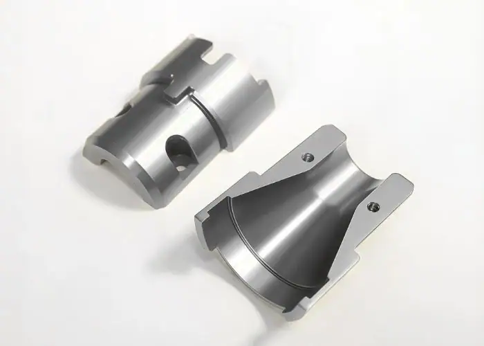
Digital calculations reduce arithmetic errors and simplify parameter selection. However, a calculator cannot determine whether a toolholder, fixture, or machine can safely support the calculated cutting conditions.
Reliable optimization combines mathematical calculation, tool-specific data, and actual machining feedback.
SFM Calculators and Reference Charts
An sfm calculator uses cutting diameter, spindle RPM, or target SFM to calculate the missing variable. It is useful when comparing cutter sizes or setting initial machining parameters.
For example, an operator can enter 500 SFM and a 0.5-inch cutter diameter to calculate approximately 3,820 RPM.
A reference chart provides suggested cutting speeds for specific tool and material combinations. The calculator converts those values into machine settings, while the chart supplies the starting cutting-speed recommendation. Both must be used correctly.
CNC Programming and Tool Manufacturer Data
CAM systems and CNC programming software can calculate spindle speeds and feed rates from tool libraries and machining parameters.
Tool manufacturer databases are particularly valuable because they account for actual cutter materials, coatings, geometry, and intended applications. Their recommendations are usually more relevant than generic SFM charts.
A complete tool record should include cutter diameter, effective cutting teeth, material compatibility, speed recommendations, and suitable feed per tooth. Keeping this information consistent helps reduce programming errors across different jobs.
Tool Wear Monitoring and Cutting Parameter Adjustment
Tool wear monitoring helps determine whether the selected SFM remains suitable during machining. Wear can be evaluated through cutting-edge inspection, spindle load, surface finish, cutting sound, and dimensional trends.
If tools wear faster than expected, engineers should examine cutting speed, chip load, engagement, coolant, tool runout, and workholding before changing parameters.
For repeat production, a validated cutting process can be documented with tool-life limits and inspection intervals. This supports more predictable machining quality and reduces unexpected tool failures.
What Happens When SFM Settings Are Incorrect?
Incorrect SFM settings can cause excessive tool wear, overheating, built-up edge, unstable chip formation, chatter, poor surface finish, and inefficient production. Excessively high cutting speed can increase thermal stress and accelerate wear, while excessively low speed may reduce productivity or contribute to unfavorable cutting behavior under certain conditions.
The actual result depends on the material and tool. A speed that is too high for one operation may be acceptable for another using a different carbide grade, coating, or cutting strategy.
Troubleshooting should begin with observable symptoms and measured process conditions. Adjustments should be made systematically rather than changing speed and feed simultaneously without understanding the cause.
What Happens When SFM Is Too High?
When SFM is too high for the tool and material, cutting temperature and wear may increase rapidly. The cutting edge may experience accelerated flank wear, coating deterioration, cratering, or premature failure.
High SFM can also contribute to dimensional variation when the tool or workpiece experiences excessive heating. Difficult alloys may become particularly sensitive to unstable thermal conditions.
The corrective action is to compare the programmed speed with the tool manufacturer’s recommendations and evaluate engagement, coolant, and chip load. Simply reducing SFM without reviewing the rest of the process may not solve the problem.
What Happens When SFM Is Too Low?
When SFM is too low, machining productivity may decrease because the cutter operates at a lower rotational speed than the process could support.
Depending on tool geometry, material, and chip load, insufficient speed can also contribute to poor chip formation or built-up edge. However, low speed is not inherently damaging in every application.
The correct adjustment is to verify the intended cutting range and ensure chip load remains appropriate. Cutting speed and feed rate should be reviewed together rather than optimized independently.
Common SFM Calculation and Setup Mistakes
Common SFM errors involve using the wrong diameter, mixing imperial and metric units, applying unsuitable cutting-speed recommendations, or confusing RPM with linear feed rate.
A calculation can be mathematically correct but practically unsuitable if the selected material data belongs to a different tool grade or operation.
| Mistake | Possible Result | Corrective Action |
| Using Millimeters in the Imperial Formula | Incorrect RPM | Convert diameter to inches |
| Confusing SFM With RPM | Wrong spindle setting | Use the correct conversion formula |
| Using Nominal Instead of Effective Diameter | Incorrect cutting speed | Verify cutting geometry |
| Ignoring Spindle Limits | Unachievable or unsafe setting | Check machine and tooling ratings |
| Copying SFM Across Different Materials | Excessive wear or slow machining | Use material-specific cutting data |
| Ignoring Feed per Tooth | Rubbing or excessive chip load | Recalculate feed after RPM changes |
For accurate results, confirm the units, cutter geometry, material condition, and actual tool specification before entering parameters into the CNC program.
How to Correct Chatter, Excessive Heat, and Tool Wear
Chatter, excessive heat, and premature tool wear require different corrective actions. Chatter often points to vibration, weak workholding, tool overhang, or unsuitable cutting engagement.
Excessive heat may be associated with high cutting speed, poor chip evacuation, heavy engagement, or insufficient cooling. Tool wear may result from a combination of abrasive material behavior, cutting temperature, and unsuitable tool selection.
A practical troubleshooting sequence is:
- Verify material grade, cutting tool specification, and programmed SFM.
- Check spindle RPM, chip load, and cutter engagement.
- Inspect the cutting edge, toolholder, and workpiece setup.
- Review cooling and chip evacuation.
- Adjust one relevant parameter at a time and verify part quality.
This approach helps identify the cause rather than masking the problem through arbitrary parameter changes.
Where Is SFM Used in Precision CNC Manufacturing?
SFM is used throughout precision CNC manufacturing wherever cutting speed must be controlled for reliable tool performance and part quality. Typical applications include automotive parts, industrial machinery, medical instruments, and aerospace components. The required SFM depends on material, cutting tool, part geometry, and machining conditions rather than the industry name alone.
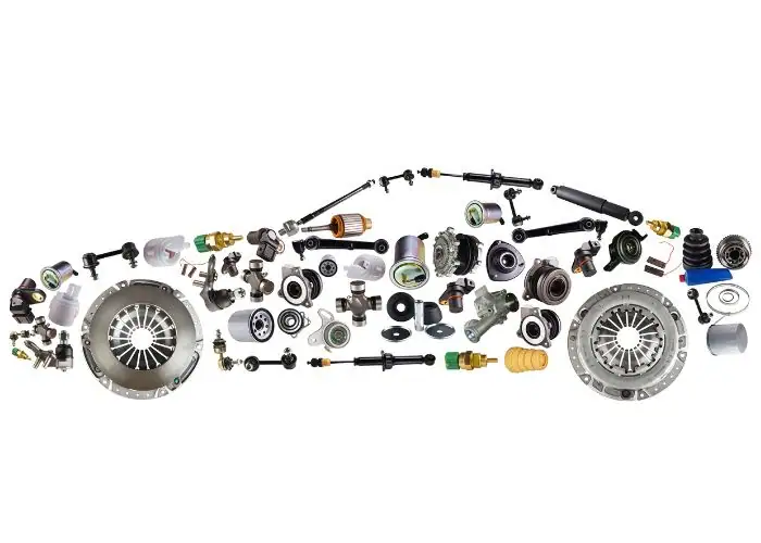
Precision components often include features that require different machining strategies. A single part may use high-speed aluminum milling for a housing, lower-speed drilling for holes, and controlled turning for a precision shaft.
SFM helps connect the material and cutting tool to the machining program. Correct speed selection supports consistency, but the drawing’s tolerance and surface requirements still determine the final manufacturing and inspection strategy.
Automotive Components
Automotive machining uses SFM calculations for parts such as transmission housings, shafts, brackets, engine components, and precision mechanical assemblies.
Large production batches make tool life and cycle time especially important. A cutting-speed setting that works for one prototype may need further validation before high-volume production.
When processing steel shafts or aluminum housings, SFM selection should reflect the material, cutter, and feature being machined. Reliable settings reduce unexpected tool changes and help maintain dimensional consistency.
Industrial Equipment and Precision Machinery
Industrial equipment manufacturing uses SFM calculations for machine bases, valve bodies, shafts, fixtures, hydraulic components, and automation parts.
These components vary widely in material and geometry. A large aluminum fixture plate may use different cutting speeds from a stainless steel valve component or hardened steel shaft.
Machinists must also consider setup rigidity and tool engagement. Large or difficult-to-clamp parts may require more conservative parameters even when the cutting tool supports higher theoretical speeds.
Medical Devices and Instruments
Medical component machining uses controlled cutting speeds for stainless steel instruments, titanium components, precision housings, and specialized mechanical parts.
Material behavior and surface integrity are particularly important. Incorrect cutting conditions may create burrs, unstable finishes, or tool wear that affects dimensional consistency.
For small precision features, cutter diameter and spindle capability become critical. Appropriate SFM calculations help establish initial speed settings, while inspection verifies that the finished part meets its engineering requirements.
Aerospace Components
Aerospace machining uses SFM calculations for aluminum structures, titanium components, stainless steel parts, and high-performance alloy components.
These materials can require very different cutting speeds. Aluminum may support relatively high SFM with suitable tooling, while titanium and nickel-based alloys often require more conservative cutting conditions.
Because aerospace components may involve expensive materials and demanding specifications, cutting parameters should be verified carefully. Stable machining, proper tool selection, controlled heat, and consistent inspection help protect part quality.
FAQs
How To Calculate Feed Rate For CNC Milling?
To calculate feed rate for CNC milling, multiply spindle RPM by the number of effective cutting teeth and feed per tooth. The formula is F = RPM × Z × fz. For example, a four-flute cutter running at 3,000 RPM with a chip load of 0.003 inch per tooth gives 36 IPM. The chip load must match the tool diameter, material, and cutting engagement. This calculation determines table feed, not SFM, which is calculated separately from diameter and spindle speed.
How To Calculate Speed And Feed?
Calculate cutting speed and feed by first selecting a suitable SFM for the workpiece material and cutting tool. Convert SFM to spindle RPM using RPM ≈ (3.82 × SFM) ÷ cutter diameter in inches. Next, calculate feed rate using RPM × effective tooth count × feed per tooth. For example, 300 SFM with a 0.5-inch cutter gives approximately 2,292 RPM. With four effective teeth and 0.003 inch per tooth, feed is about 27.5 IPM. Verify the results against tooling specifications.
How To Calculate Surface Feet Per Minute?
Surface feet per minute is calculated by multiplying spindle RPM by the effective cutting diameter in inches and π, then dividing by 12. The formula is SFM = (π × D × RPM) ÷ 12. For example, a 1-inch cutter at 1,200 RPM produces approximately 314 SFM. In turning, use the workpiece diameter at the cutting location instead of the cutter diameter. This result describes cutting surface speed, it does not determine whether the setting is appropriate without considering the material and tool.
Conclusion
SFM machining is essential for selecting cutting speeds and converting them into practical spindle settings for CNC milling and turning. Understanding the relationship between SFM, RPM, cutting diameter, and feed rate helps engineers balance tool life, machining efficiency, and surface quality.
At TiRapid, we provide precision CNC machining and manufacturing services for custom metal and plastic components. Our team supports CNC milling, turning, material selection, DFM analysis, surface finishing, and quality inspection to help customers achieve accurate parts, stable production, and practical manufacturing solutions.