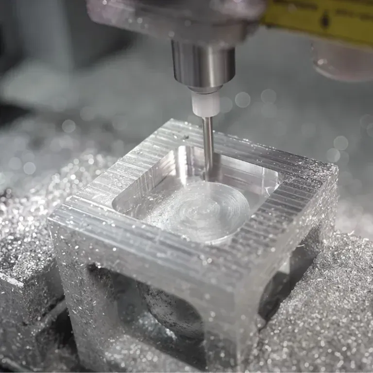
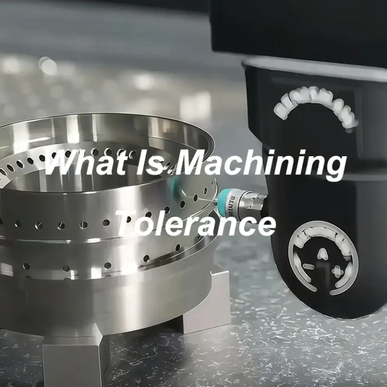
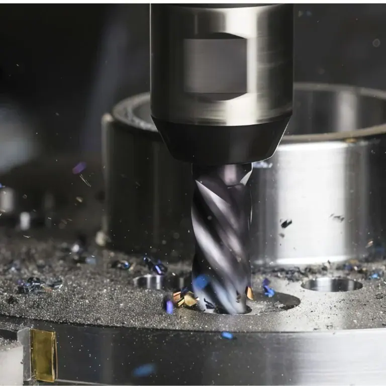
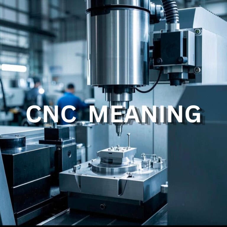
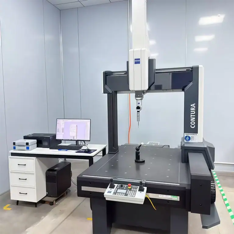
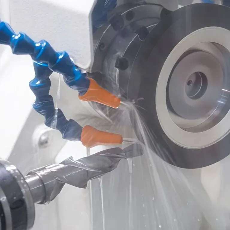
A flat mounting face, a deep pocket, and a curved mold surface call for different cutting approaches. Choosing a milling cutter starts with understanding the feature to be produced, then checking whether the tool can reach it, remove material reliably, and leave the required finish.
This guide explains the main types of milling cutters, their typical uses, and the selection factors that matter in CNC machining. For engineers and buyers, it also shows how part geometry and tooling requirements influence manufacturing effort and cost.
What Is A Milling Cutter?
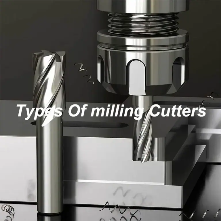
A milling cutter is a rotating cutting tool that removes material as its cutting edges engage a workpiece. Its geometry determines which surfaces it can reach and how it cuts features such as faces, walls, slots, and contours.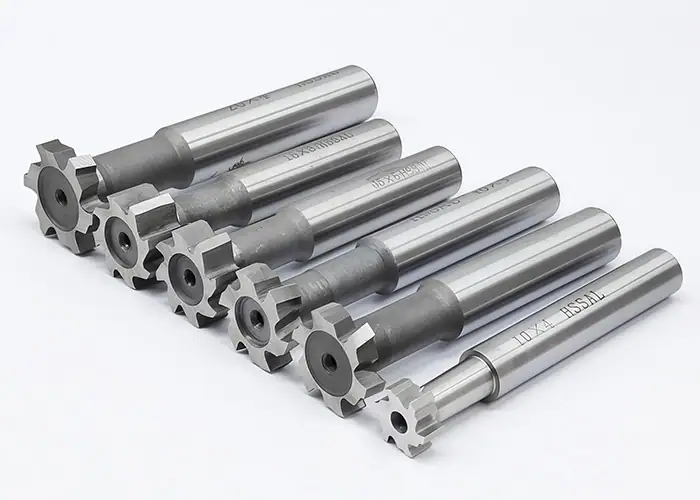
How Milling Cutters Remove Material
During milling, the spindle rotates the cutter while controlled movement between the tool and workpiece produces the required shape. Each engaged cutting edge removes a chip, then moves out of the cut before engaging again.
Peripheral cutting uses edges around the tool’s outside to machine walls or profiles. End cutting uses edges at the tool’s end to machine surfaces or enter material where the tool design permits. Many cutters combine these actions.
A drill primarily creates a hole through axial feed. An end mill can machine laterally, but direct plunging requires a suitable center-cutting design. Ramping and helical entry also depend on the cutter’s geometry and manufacturer recommendations.
How Milling Cutters Are Classified
Tool descriptions combine several attributes. A ball nose end mill describes a profile, while solid carbide describes a material and construction choice. A coating adds another specification.
Keep these categories separate when comparing tools:
| Classification | What It Describes | Examples |
| Geometry and application | Cutting shape and intended work | Ball nose, face mill, thread mill |
| Construction | How the cutting portion is built or replaced | Solid, indexable, modular |
| Cutting material | Material forming the cutting edge | HSS, carbide, PCD |
| Surface treatment | Coating applied to the cutting material | AlTiN, TiB₂, diamond coating |
An indexable cutter uses replaceable inserts. A modular system replaces a cutting head or another tool section. These construction choices can appear across different cutter families.
What Are The Main Types Of Milling Cutters?
Common milling cutters include end mills, face mills, side and face cutters, slab mills, slitting saws, and specialized tools for slots, chamfers, threads, and formed profiles. The feature shape and available access determine which family is appropriate.
The following comparison provides a starting point before the individual tool descriptions.
| Cutter Type | Typical Features | Main Selection Check |
| End mill | Pockets, walls, slots, contours | End profile, reach, and entry capability |
| Face mill | Broad flat surfaces | Cutting width, entering angle, and machine capacity |
| Side and face cutter | Open slots and grooves | Cutter width, arbor support, and access |
| Slab mill | Broad surfaces parallel to the cutter axis | Arbor arrangement and workpiece clearance |
| Slitting saw | Narrow slots and cutoffs | Thickness, depth, and lateral support |
| T-slot or Woodruff cutter | T-slots or shaft keyseats | Required form and neck clearance |
| Chamfer or dovetail cutter | Beveled edges or angled grooves | Angle and collision clearance |
| Thread mill | Internal or external threads | Thread form, pitch, and interpolation capability |
| Form mill | Specified profiles and edge radii | Match between tool form and drawing |
End Mills
End mills are widely used for CNC pockets, shoulders, slots, and external profiles. Their peripheral cutting edges machine walls, while the end geometry determines the surfaces they leave at the bottom of a cut.
Common designs include:
- Square end mills have a flat end with sharp outer corners. They suit flat-bottomed pockets, steps, and wall finishing.
- Ball nose end mills have a rounded end suited to curved surfaces and contoured finishing. Tool contact position matters because cutting speed decreases toward the center of the tip. Stepover and tool orientation help determine the resulting surface texture.
- Corner radius end mills retain a flat central end and round the outer cutting corners. The rounded corner helps resist chipping. When the tool finishes the wall-to-floor junction, its corner radius determines the nominal fillet left there.
- Roughing end mills are designed for stock removal. Serrated versions break the cutting edge into smaller sections to manage chips and cutting loads. A separate finishing pass is normally planned when the drawing requires a smoother surface or closer dimensional control.
- Undercutting end mills use relieved necks and cutting heads that reach beneath overhanging features. Lollipop cutters are a familiar example. Check the cutting coverage, neck diameter, and clearance throughout entry, machining, and withdrawal.
These descriptions overlap. A roughing tool may also have a corner radius. Select the complete tool specification rather than treating every catalog label as a separate, mutually exclusive category.
Face Mills
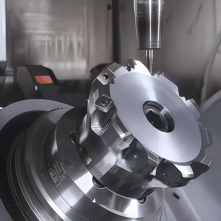
Face mills machine flat surfaces with the spindle axis generally perpendicular to the surface being produced. They commonly prepare mounting faces, reference surfaces, and broad areas of stock.
Many face mills use indexable inserts, allowing worn edges to be indexed or replaced. Insert geometry, entering angle, and cutter pitch influence cutting forces and suitability for the workpiece.
Match the tool to the available power, workholding, and surface requirements. A larger diameter covers more width, but it also changes the load on the machine and the clearance needed around fixtures and neighboring features.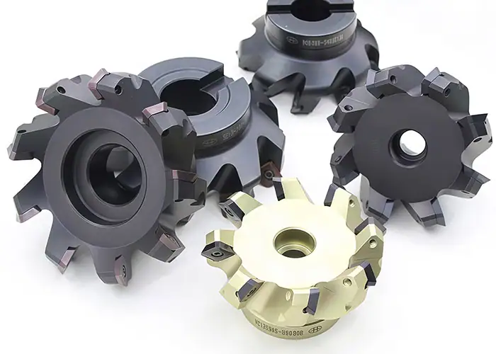
Side And Face Milling Cutters
Side and face cutters have cutting edges around their circumference and along their sides. This arrangement allows the tool to remove material from a groove while machining its side surfaces.
They are useful for accessible straight slots, grooves, and certain shoulder operations. Arbor-mounted arrangements can provide support for demanding cuts when the machine configuration permits.
Check the relationship between cutter width and finished slot width, including any adjustment or finishing allowance. A closed pocket with restricted entry may require an end mill instead.
Slab Milling Cutters
Slab mills, also called plain milling cutters, primarily cut with teeth around their cylindrical circumference. Their axis is parallel to the surface being machined, distinguishing their basic application from face milling.
They are associated with horizontal, arbor-mounted setups for broad flat surfaces. Cutter width, arbor rigidity, and workpiece access determine whether the arrangement is practical.
Their place in a tooling plan depends on machine configuration. A CNC machining center with a vertical spindle may use a face mill or end mill for the corresponding surface.
Slitting Saws
Slitting saws are thin circular cutters used for narrow slots, relief cuts, and parting operations. Their thin profile produces narrow cuts without requiring an equivalently small-diameter end mill.
The same thin section limits lateral stiffness. Arbor runout, unsupported length, chip evacuation, and sideways loading require attention.
Select the tooth form and cutting conditions for the workpiece material and engagement. Confirm that the tool and arbor can reach the intended depth without contacting adjacent surfaces.
T-Slot And Woodruff Keyseat Cutters
T-slot cutters machine the wider section beneath the opening of a T-shaped groove. A typical route first opens the narrower access slot, then machines the undercut with the T-slot tool.
Woodruff keyseat cutters produce the recessed seat for a Woodruff key in a shaft. Their disk-shaped heads may resemble other keyseat cutters, but the specified key and seat geometry govern selection.
For both tool families, check head diameter, width, neck clearance, and access. Similar appearance does not make the tools interchangeable for a specified feature.
Chamfer And Dovetail Cutters
Chamfer cutters create beveled edges and can perform controlled edge breaking or deburring. The required angle and chamfer dimensions determine the cutting profile and programmed position.
Dovetail cutters create angled undercut walls used in features such as sliding joints and locating grooves. Their wider heads require an entry route and clearance beneath the opening.
An angled tool should be selected against the actual cross-section. A chamfer and a dovetail may share an angle while requiring different cutting coverage, neck relief, and tool access.
Thread Mills
Thread mills generate threads through coordinated cutter rotation and a helical toolpath. Suitable tools and machine motions can produce internal or external threads.
Unlike a tap, a thread mill follows a programmed path rather than advancing as a full-size threaded tool through the hole. The tool form, thread standard, pitch, and cutting length must match the intended application.
For internal threads, confirm hole preparation, cutter-to-hole clearance, usable depth, and chip removal. Diameter adjustment through the toolpath is useful, but thread inspection remains necessary to verify the finished result.
Form Mills And Other Specialized Cutters
Form mills produce a specified profile through the shape of their cutting edges. Examples include tools for edge radii and selected gear-tooth forms.
A corner rounding cutter forms a radius on a workpiece edge. This differs from a corner radius end mill, whose rounded cutting corner typically produces a concave transition at a wall-to-floor junction.
Other specialized cutters have narrower applications:
| Tool | Typical Use | Planning Consideration |
| Fly cutter | Flat-surface machining with a sweeping cutting edge | Balance, rigidity, and safe operating limits |
| Hollow mill | Machining an external cylindrical feature with inward-facing edges | Feature size and access |
| Gear form cutter | Producing a specified tooth-space profile | Tooth geometry, indexing, and inspection |
Select a specialized cutter when its form or production method offers a practical way to produce the specified feature.
How Do Cutter Materials And Coatings Affect Selection?
The cutting material and coating influence wear resistance, edge behavior, and compatibility with the workpiece. Choose them alongside cutter geometry and operating conditions, rather than assuming one material or coating is best for every job.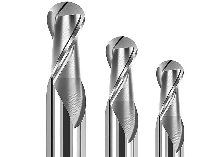
HSS And Carbide Milling Cutters
High-speed steel, or HSS, offers useful toughness and remains practical for many general-purpose and specialized cutters. Cobalt-alloyed and powder-metallurgy variants extend the available choices.
Carbide provides high hardness, wear resistance, and stiffness. It supports productive CNC machining when the cutting conditions and setup suit the selected grade and geometry. Its cutting edges can be sensitive to impact, poor rigidity, and mishandling.
Avoid choosing solely by the workpiece’s hardness. A carbide tool can be appropriate for aluminum, while an HSS cutter may be practical for a steel feature under suitable conditions. Material, production volume, tool form, and machine capability should be considered together.
PCD And Other Specialized Cutting Materials
Polycrystalline diamond, or PCD, is used in selected nonferrous and abrasive-material applications, including aluminum machining. Its wear resistance can be valuable where maintaining the cutting edge over a production run matters.
PCD is primarily selected for nonferrous work. Ferrous applications generally require a different cutting material suited to the alloy and operation.
Ceramic cutting materials serve specialized applications, including selected heat-resistant alloy machining. These require an appropriate grade, process, and operating conditions rather than a simple upgrade from a general-purpose tool.
Coated And Uncoated Cutters
A coating changes the surface properties of the tool. Depending on its composition and application, it can improve resistance to wear, heat, or material adhesion.
Coatings for steel machining should not automatically be transferred to aluminum. Uncoated, polished tools and coatings designed for nonferrous work can offer more appropriate edge and friction characteristics for particular applications.
PCD cutting edges and diamond-coated carbide are also different constructions. Evaluate the complete tool recommendation instead of relying on the word diamond.
How Do You Choose The Right Milling Cutter?
Select a cutter by defining the feature and operation, matching the workpiece material, checking access and tool dimensions, and verifying compatibility with the machine and holder. Then establish cutting conditions for that specific combination.
Start With The Feature And Milling Operation
Read the drawing and model before choosing a catalog tool. Identify what must be removed, the surfaces that must remain, and how the tool can enter and leave the cut.
Separate bulk material removal from the final surface-generating operation. A roughing tool may clear a pocket efficiently, while another tool finishes its walls, floor, or internal details.
For a closed pocket, entry capability can eliminate an otherwise suitable cutter. For an undercut, the cutting head may reach the feature while the neck or holder still collides with the part. Review the complete entry and withdrawal paths as well as the cutting position.
Match The Tool To The Workpiece Material
Use the actual material specification, including condition where relevant. Different aluminum alloys, steel heat treatments, or plastic grades can change the tooling requirements.
Consider adhesion and chip evacuation in aluminum, heat and edge loading in difficult alloys, and heat sensitivity or abrasive fillers in engineering plastics. A tool suited to an unfilled polymer may not suit a glass-filled grade.
Manufacturer application guidance provides the starting point for geometry, coating, and cutting data. Refine the process through the actual setup rather than applying a generic material label to every job.
Check Diameter, Cutting Length, And Reach
Diameter must fit the feature and leave room for the programmed movement. A cutter that fits the slot width may still be unsuitable for its entry method or finishing strategy.
Length of cut describes the axial extent of the cutting edges. Reach describes access below a larger tool section, while installed overhang is the distance extending from the holder. These dimensions are related but not interchangeable.
Use sufficient reach without adding unnecessary overhang. Review the neck and holder against the entire cavity, particularly around steps, angled walls, and clamps. More cutting length does not automatically provide more usable depth.
Consider Flute Count And Chip Evacuation
Flute count influences the available chip space and cutting-edge engagement. It must be considered alongside the material, flute geometry, and amount of radial engagement.
Full-width slotting places different demands on chip evacuation from light side finishing. A tool with more flutes may suit a particular finishing pass but crowd chips during another operation.
Helix and pitch also affect cutting behavior. Variable designs can help manage vibration in suitable applications, but they do not compensate for an unstable holder or unsupported workpiece.
Verify Machine And Toolholder Compatibility
Check spindle speed, available power and torque, holder interface, and the permitted operating limits of the assembled tool. Large cutters and small cutters can impose very different requirements on the same machine.
Runout changes how cutting loads are shared between edges. Holder condition, correct assembly, and suitable gripping length therefore matter alongside the cutter itself.
Confirm workholding, coolant delivery, and chip removal before production. Simulate or otherwise verify tool clearance, then validate the program under controlled conditions. A catalog recommendation becomes a production process only after these practical checks.
How Does Cutter Selection Affect Part Design And Cost?
Part geometry determines tooling access, and tooling access influences machining time, finishing effort, and production risk. Design choices that permit stable cutting with available tools can make a part easier to manufacture without changing its function.
Internal Corners, Deep Pockets, And Undercuts
In a pocket viewed from above, the rotating cutter leaves an internal radius related to its diameter. A square end mill does not eliminate this side-wall corner radius. Its sharp end corner addresses a different feature: the transition between a wall and a flat floor.
Where function permits, providing a larger internal corner radius can allow a more rigid tool and a smoother path. Deep pockets and small corner radii together can force a difficult combination of small diameter and long reach.
Undercuts add access constraints beyond the cutting surface itself. Discuss the entry opening, neck clearance, and possible setup changes during design review, before the geometry is released for production.
Surface Finish And Dimensional Requirements
The cutter contributes to the finished surface, but toolpath, step spacing, vibration, runout, wear, and workpiece movement also influence the outcome.
Specify surface finish and tolerances where the part needs them. A finishing strategy should address those functional surfaces, with an inspection method capable of checking the requirement.
For curved surfaces, changing the finishing tool or path may alter the remaining tool marks. For a precision wall, managing deflection and wear may be more important than changing the cutter’s nominal shape. Evaluate the process against the particular feature.
Standard Tooling And Total Machining Cost
Tool purchase price is only part of machining cost. Setup, programming, cycle time, tool changes, inspection, and replacement all contribute to the finished part’s cost.
Standard tooling may shorten preparation, while a custom form tool may justify its development effort when a repeated feature or production volume supports it. Compare the complete manufacturing routes, including preparation and production, over the expected order quantity.
For example, an aluminum housing may use a face mill for its mounting face, a larger end mill to clear the pocket, and a smaller tool for local details. Requiring the smallest tool throughout the cavity can increase machining effort. Reviewing the pocket geometry may allow bulk material removal with a stiffer cutter while preserving the critical detail. Any drawing change needs engineering approval before it becomes part of the quoted process.
For a quotation, provide the drawing, model, material, quantity, finish, and critical requirements. These inputs allow the manufacturer to evaluate whether a feature needs special tooling or whether a practical design adjustment could simplify production.
FAQs
Why Does A Milling Cutter Leave Chatter Marks On A Part?
Chatter marks result from vibration during cutting. Common contributors include excessive tool overhang, weak workholding, unsuitable cutting conditions, and tool wear. Check tool and fixture rigidity first, then review spindle speed, feed, and cutter engagement. Changing the cutter alone may not resolve the underlying problem.
When Is A Custom Milling Cutter Worth The Additional Cost?
A custom cutter may be worthwhile when standard tools cannot produce the required feature efficiently, or when it can combine repeated operations. Compare the expected savings in machining time and tool changes against development, replacement, and maintenance costs over the planned production quantity.
Do I Need To Specify The Milling Cutter When Ordering CNC Parts?
Usually, no. Provide the material, geometry, tolerances, surface finish, quantity, and inspection requirements. The manufacturer can then select suitable tooling and machining methods. Specify a particular cutter when it is required by an approved process, drawing, or contract, and communicate that requirement before quotation.
Conclusion
Understanding types of milling cutters makes it easier to connect a drawing with a workable manufacturing process. Start with the required feature, then evaluate tool geometry, cutting material, construction, access, and equipment compatibility. A suitable cutter must work within the complete setup and deliver the specified result.
TiRapid provides precision CNC machining for complex metal and engineering plastic parts. Our team reviews part geometry, material requirements, and critical dimensions to plan practical machining approaches. Send us your drawings, CAD model, quantity, and project requirements for manufacturing feedback and a tailored quotation.