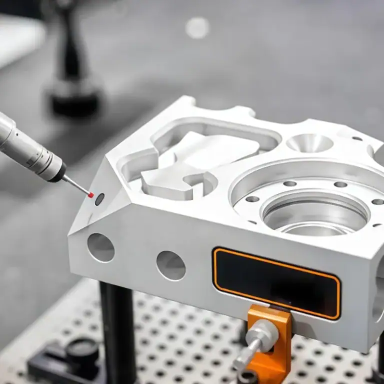
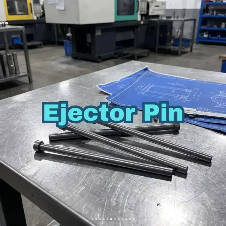
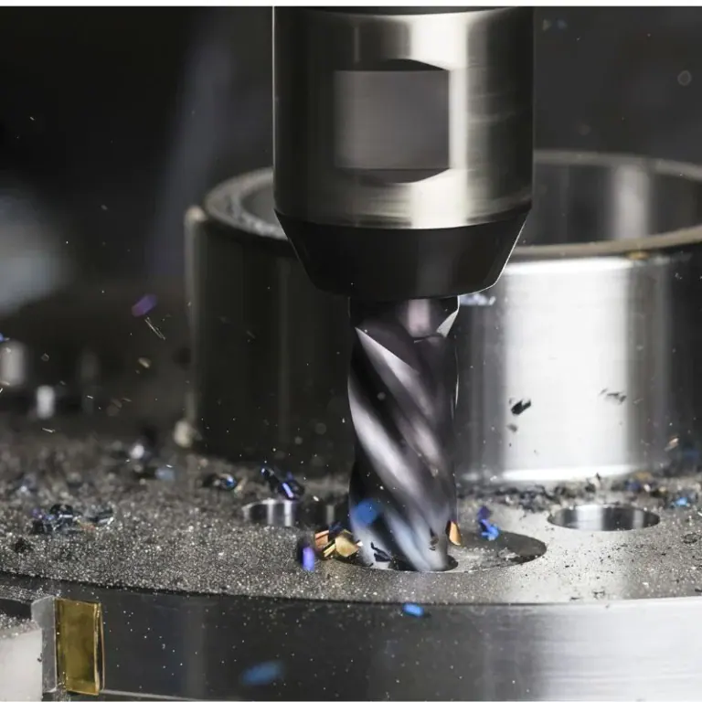
A machined housing can have a flat mounting face, a deep pocket, a bearing seat, and threaded holes. A shaft may need finished diameters, grooves, and an axial bore. Each feature places different demands on the cutting edge, so producing a complete part usually requires several tools working through a planned sequence.
Understanding CNC machining tools helps engineers assess manufacturability and helps buyers ask useful questions about a proposed process. This guide explains the main tool families, how to select them for part requirements, and how toolholding and workholding support their performance.
What Are CNC Machining Tools?
CNC machining tools are the tools used to shape and finish workpieces on computer-controlled machines. The main cutting tools include milling cutters, turning tools, drills, boring tools, reamers, and threading tools. Their geometry and application determine which features they can produce.
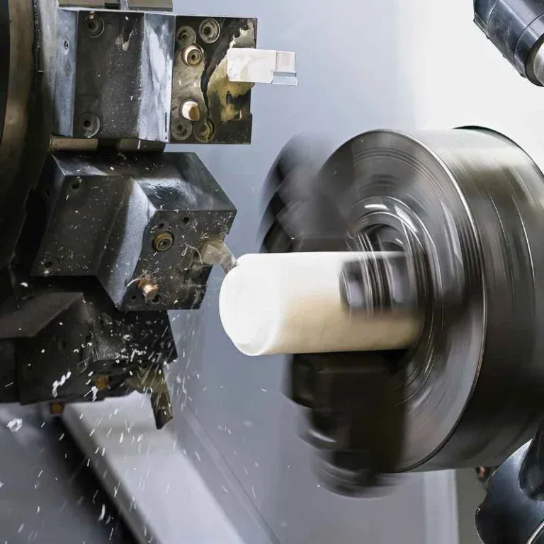
The CNC machine supplies controlled movement, power, and positioning. The cutting tool engages the material. During milling, the cutter normally rotates while following a programmed path. In conventional turning, the workpiece rotates against a tool that moves along its surface.
The term CNC cutting tools specifically describes tools that remove material through cutting. Broader discussions of CNC tooling also include toolholders, fixtures, and setup equipment. A collet holds a cutter, a fixture locates the workpiece, and a probe supports measurement. These supporting devices have different functions from the cutting edge itself.
What Are The Main Types Of CNC Machining Tools?
The main tool families are organized around milling, turning, holemaking, threading, grooving, and edge finishing. Select a family according to the required feature, then evaluate the specific tool against access, material, and drawing requirements.
| Operation | Common Tools | Typical Features | Main Selection Check |
| Milling | End mills, face mills | Faces, pockets, walls, profiles | Cutter and holder access |
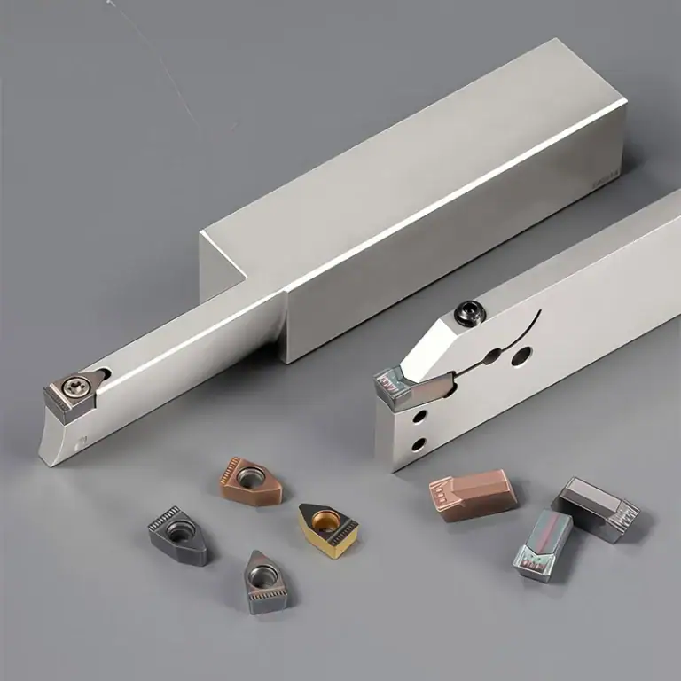
| Turning | Turning inserts and holders | Outside diameters, shoulders, end faces | Edge geometry and workpiece support |
| Drilling | Twist drills, specialized deep-hole drills | Initial holes | Depth and chip evacuation |
| Boring | Boring bars, adjustable boring heads | Enlarged or finished bores | Rigidity and available allowance |
| Reaming | Reamers | Finished hole size and surface | Quality of the preceding hole |
| Threading | Taps, thread mills, threading inserts | Internal and external threads | Thread specification and usable depth |
| Grooving And Parting | Grooving inserts, parting blades | Recesses, retaining-ring grooves, separation cuts | Width, reach, and chip control |
| Edge Finishing | Chamfer mills, countersinks, deburring tools | Chamfers, screw seats, burr removal | Specified edge geometry and access |
Milling Cutters
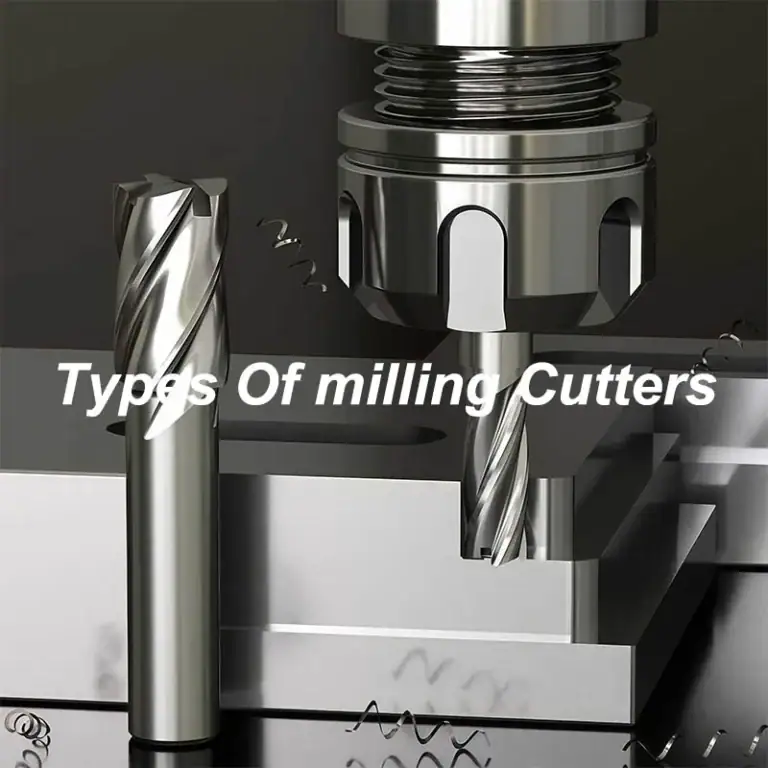
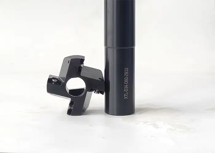
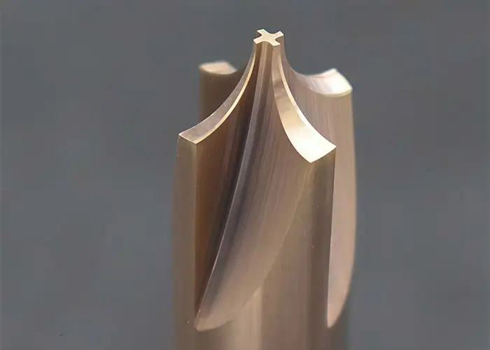
Milling cutters machine flat surfaces, pockets, slots, walls, and contoured features. End mills use their cutting ends and peripheral edges for a range of operations. Face mills commonly produce broad, flat faces, often using replaceable inserts.
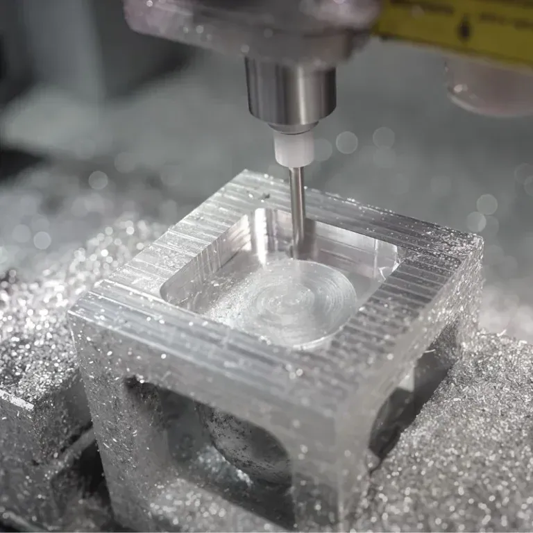
For a housing, an end mill may open an internal pocket while a face mill prepares the mounting surface. Cutter diameter affects corner access, and the complete tool assembly must clear surrounding walls and clamps. These constraints can influence the part layout before machining begins.
For a closer comparison of ball nose, corner radius, slotting, and other profiles, see our guide to types of milling cutters.
Turning And Facing Tools
Turning tools machine rotating parts such as shafts, sleeves, and bushings. External turning establishes outside diameters and stepped profiles. Facing produces end surfaces, while suitable profiling tools follow shoulders, tapers, and contours.
Many turning assemblies combine a replaceable insert with a holder. The holder positions and supports the insert, while the insert geometry, cutting material, and nose radius influence how the edge cuts and forms chips. Both must suit the available approach direction and surrounding features.
Roughing and finishing place different demands on the edge. A geometry designed for heavier cuts may not control chips effectively during a light finishing pass. Planning should match the insert to the actual feed and depth of cut, while accounting for the stiffness of the workpiece. A slender shaft may need additional support and a different cutting strategy from a short, rigid bushing.
Drilling Tools
Drills create holes by advancing into the workpiece. Common options include solid drills and designs with replaceable tips or inserts. Twist drills are widely used, while specialized deep-hole tools address applications where reach, guidance, and coolant delivery require a dedicated approach.
Hole depth, entry surface, exit conditions, and chip evacuation are central selection factors. An inclined entry can load the cutting edges unevenly. Chips trapped inside a deep hole can damage the tool or the hole surface. Tool geometry, coolant supply, and the drilling cycle therefore need to work together.
A spotting operation may help establish a suitable entry for some drill designs, but its geometry must be compatible with the drill. It should not be added automatically to every holemaking route. Likewise, drilling alone may satisfy a clearance-hole requirement. Additional finishing is justified when the drawing or demonstrated process capability calls for it.
Boring Tools
Boring tools enlarge or finish an existing hole. A lathe commonly uses a boring bar inside a rotating component, while a machining center may use a rotating boring head. Adjustable fine-boring systems allow the cutting diameter to be set for the required bore.
Boring is useful for bearing seats, bushing locations, and other internal features whose diameter and relationship to surrounding geometry matter. With suitable stock allowance and a stable setup, the operation can improve the hole’s geometry and establish its axis relative to the machining setup.
Access and rigidity are important limitations. A small bore restricts bar diameter, while a deep bore increases the required overhang. The resulting assembly must still provide chip clearance and resist deflection. Evaluate the bar and holder together with cutting forces, allowance, and workpiece support.
Reaming Tools
Reamers finish a previously machined hole by removing a relatively small allowance. Their multiple cutting edges can bring a prepared hole to the required size and surface condition, making them useful for locating holes and other repeated hole features.
The preceding operation is essential. The hole must provide suitable stock for the selected reamer, and the tool must enter with appropriate alignment. Too little or uneven allowance can prevent the reamer from cutting consistently.
Reaming should not be expected to correct positional or straightness errors in the original hole. If location or alignment is the main concern, the process may need a different preparation or a boring operation. Choose between boring and reaming according to the drawing and the condition of the existing hole.
Taps And Thread Mills
Cutting taps produce internal threads in prepared holes. Spiral-point designs commonly direct chips forward in through holes, while suitable spiral-flute designs draw chips back from blind holes. The material and hole geometry determine whether a particular tap design is appropriate.
Forming taps create threads by displacing ductile material instead of cutting chips. They require a compatible workpiece material, controlled hole preparation, and suitable lubrication. Their chip-free action does not make them interchangeable with cutting taps.
Thread mills cut threads through a coordinated helical toolpath. They require compatible machine motion and enough clearance for the cutter to enter and follow its path. Where the cutter design permits, a thread mill can cover different thread diameters with the same pitch and form.
Tapping often provides a direct route for a recurring internal thread size. Thread milling offers programmed adjustment of thread diameter and can be useful when chip control or a range of diameters makes that flexibility valuable.
Confirm the thread designation, tolerance class, and usable full-thread depth. A blind hole needs clearance for the selected tool and any drill-point geometry beyond the required full threads. External threads on turned parts can also be produced with dedicated threading inserts.
Grooving And Parting Tools
Grooving tools produce recesses on outside diameters, inside bores, or end faces. Applications include retaining-ring grooves, seal grooves, and clearance features. Parting tools cut through a turned workpiece to separate the component from bar stock or a remaining section.
The insert and supporting blade or holder must accommodate the groove width, depth, and approach direction. A tool that reaches an external groove may not be suitable for a face groove or an internal recess. Nearby shoulders can also restrict the holder even when the cutting edge appears accessible.
These operations can concentrate cutting loads in a narrow space. Keep the assembly as rigid as access allows and provide a route for chips to escape. During parting, the process must also account for workpiece stability and how the separated component will be controlled.
Chamfering And Deburring Tools
Chamfering tools create defined angled edges. Countersinks produce conical recesses, often for screw heads. Deburring tools remove unwanted material left at an edge after another operation. The functions overlap in some applications, but the required finished geometry determines the tool choice.
A drawing may require a dimensioned chamfer at one opening and only burr removal at another. Enlarging both edges with the same operation can change a functional surface or reduce the usable thread depth.
Back edges and intersecting holes deserve attention during planning. A cutter that reaches the front of a hole may not reach its exit or an internal intersection. Specialized back-chamfering or cross-hole deburring tools can address accessible applications, while other features may require a separate finishing method. Define the edge requirement early enough to include the necessary access and inspection.
How Do You Choose CNC Tools For Part Requirements?
Choose CNC machining tools by connecting each feature to its material, dimensional requirements, access constraints, and production quantity. Then check whether the machine and complete tool assembly can perform the proposed operation reliably.
Start With Feature Geometry And Access
Begin with the finished feature and the direction from which it can be machined. A bore, a face groove, and a threaded blind hole may sit close together while requiring very different approaches.
Check the swept space of the entire assembly, including the shank, holder, and extensions. Also allow for entry, withdrawal, and chip removal. A tool that fits inside the final CAD shape may still collide during its approach.
Useful drawing and model checks include:
- Features hidden behind shoulders or narrow openings.
- Deep bores that limit bar diameter and stiffness.
- Threads with little space beyond the required full-thread depth.
- Edges that become inaccessible after another operation.
Where access drives an unusually long or specialized tool, discuss a feature adjustment before finalizing the design. A small change to an opening or relief can create a more practical machining route.
Match The Process To Size, Location, And Finish Requirements
A hole’s diameter, position, form, and surface texture are separate requirements. Meeting the diameter tolerance does not establish that the axis is correctly located or that the surface meets its finish specification.
Separate the acceptance criteria before choosing a finishing route. A bore can meet its size requirement while failing a cylindricity or positional requirement. The operation and setup must address every applicable callout, including relationships between features and any specified datum system.
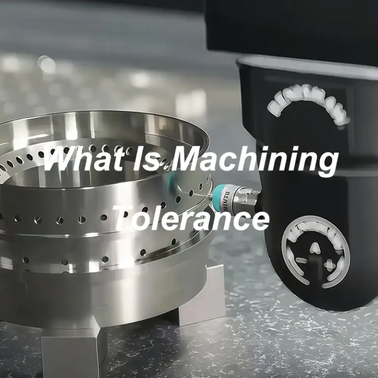
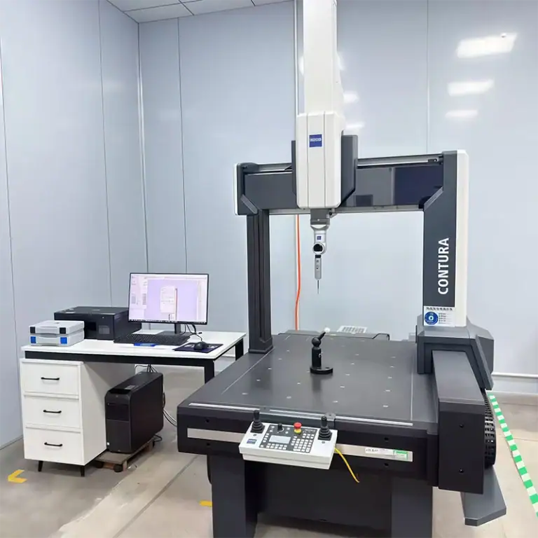
Plan inspection around the same requirements. A bore gauge can assess diameter, but that measurement alone does not establish position relative to a datum. Coordinate measurement or another suitable method may be needed for location and geometric relationships. A specified surface texture also needs an appropriate verification method. Choosing the finishing operation and inspection approach together avoids treating a single diameter reading as proof of complete conformity.
Match Tool Geometry And Cutting Material To The Workpiece
Specify the alloy and condition rather than a broad label such as metal or plastic. Hardness, chip behavior, abrasiveness, and the tendency to adhere to the edge affect tool choice.
In turning, insert grade and chipbreaker geometry must work with the material and cutting conditions. A sharp edge suitable for a ductile aluminum alloy may be a poor choice for an interrupted cut in hardened steel. For drills and taps, the flute and cutting-edge design must also manage the chips produced by that material.
High-speed steel and carbide offer different combinations of toughness, wear resistance, and operating capability. Coatings must suit the substrate, workpiece, and application. A coated tool is not automatically the best option for every material.
Use toolmaker recommendations as a starting point, then establish the cutting conditions for the real setup. Copying a speed or feed from another job without checking material condition, tool engagement, and coolant delivery can undermine an otherwise sensible selection.
Consider Production Quantity And Tool Management
Prototype work often favors readily available tools and a process that can accommodate design changes. A dedicated tool becomes more attractive when a stable design and expected order quantity justify its preparation and replacement requirements.
For repeated production, assess how tools will be identified, preset, inspected, and replaced. Define which tools control critical features and how wear will be detected before those features drift outside their limits. Replacement inserts or tools should have a controlled setup procedure so the process remains consistent after a change.
Compare total manufacturing cost rather than cutter purchase price alone. Relevant costs include setup, machining time, tool changes, inspection, and the consequences of rework or scrapped parts. Procurement teams can ask how the proposed tooling supports repeat orders and what changes would require the process to be checked again.
How Do Toolholding And Workholding Support CNC Tools?
Toolholding secures and positions the cutting tool, while workholding locates and supports the part. Both affect whether the selected tool can produce the intended feature consistently, especially when reach or part stiffness is limited.

Toolholders, Collets, And Tool Setup
Rotating tools use compatible chucks, collets, or other holders to connect to the spindle. Turning inserts and boring bars use holders suited to the turret or machine interface. The connection must provide appropriate grip, clearance, and rigidity for the operation.
For a rotating assembly, runout affects how evenly the cutting edges engage. Clean mating surfaces, correct assembly, and suitable clamping help control it. Keep unsupported tool length as short as the feature and holder clearance allow, while maintaining the specified gripping length.
Tool length, diameter, and relevant offsets must correspond to the actual assembly. Presetting and in-machine measurement can support this setup. An accurate offset cannot compensate for an unstable holder, and a rigid holder cannot correct an incorrectly entered tool dimension.
Fixtures, Datums, And Workpiece Support
A fixture establishes how the part is located and restrained during machining. Its locating surfaces should support the chosen datum strategy, particularly when a feature’s position depends on an earlier operation.
Clamping must resist cutting loads without distorting the component. Thin walls and slender sections may need local support or a revised sequence so that material removal does not leave a flexible feature exposed to heavy cutting forces.
Access, support, and measurement must remain compatible throughout the route. For parts that can deform under clamping, the inspection plan should also establish the required restraint condition. Measuring a tightly clamped component can conceal movement that appears after release.
How Are CNC Tools Combined To Machine A Complete Part?
A complete part is produced by combining tools around its features and planning how each operation prepares for the next. The sequence should preserve useful locating surfaces, provide finishing allowance where needed, and keep critical features accessible.
Example Of A Housing With Precision Holes And Threads
Consider an aluminum housing with a mounting face, an internal pocket, a precision bore, and threaded attachment holes. A possible tooling plan assigns a different role to each operation:
| Part Feature | Possible Tool | Purpose In The Process |
| Mounting face | Face mill | Establish a surface used for mounting or subsequent location |
| Internal pocket | End mill | Remove internal stock and finish accessible walls |
| Clearance and pilot holes | Drill | Produce holes to finished size or prepare for another operation |
| Precision bore | Fine-boring tool or reamer | Finish the bore through a route matched to its requirements |
| Attachment threads | Cutting tap or thread mill | Produce the specified usable thread |
| Opening edges | Chamfering or deburring tool | Establish the required edge condition |
The important decision is how these operations interact. If a bore’s position is specified relative to the mounting face, the setup must establish that relationship. If the pocket leaves a thin wall around the bore, the planner must account for the change in stiffness before final sizing.
Thread preparation also affects later work. The hole depth must accommodate the selected threading method, and edge finishing must preserve the required full-thread depth. The final plan should explain which surfaces locate the housing and how critical relationships will be checked.
Example Of A Turned Shaft Or Bushing
A stepped shaft might combine external turning, facing, axial drilling, grooving, and external threading. A bushing may add internal boring or reaming to establish its bore. A parting tool may separate either component from bar stock.
The setup determines how these tools work together. Features machined while the part remains in a common setup can share that locating condition. Features completed after transfer require a deliberate method of locating and supporting the component again.
For a bushing with a thin wall, finishing the outside diameter and bore requires attention to clamping deformation and cutting loads. For a slender shaft, removing material can reduce stiffness before the final diameters are complete. These concerns may change the roughing sequence, finishing allowance, or support arrangement.
The tooling plan therefore extends beyond a list of cutters. It should connect the chosen edges and holders to the stock, workholding, operation sequence, and inspection requirements of the finished part.
FAQs
How Does Tool Wear Affect CNC Machining?
Tool wear can cause dimensional drift, poorer surface finish, and inconsistent part quality. Monitoring wear and replacing or indexing tools before they exceed process limits helps maintain repeatability.
What Is A Tool Offset In CNC Machining?
A tool offset is a value stored in the CNC control to account for tool geometry, such as length or radius. Wear offsets allow small dimensional corrections as the cutting edge wears.
What Is Live Tooling On A CNC Machine?
Live tooling uses powered, rotating tools on a CNC lathe or turning center for milling, drilling, and tapping. It allows more features to be machined in one setup, reducing transfers between machines.
Conclusion
Choosing CNC machining tools starts with understanding what each feature requires. Milling cutters, turning tools, drills, boring tools, reamers, and threading tools each serve a different purpose. A practical process combines them with suitable holders, workpiece support, and inspection that verifies the specified result.
TiRapid provides precision CNC machining for custom metal and engineering plastic parts, with manufacturing feedback and dimensional inspection for prototypes and low-volume production. Send your CAD model, drawing, material, quantity, and critical requirements to discuss a practical machining approach and request a quote.