
PCB manufacturing equipment involves multiple processes, including drilling, routing, conveying, positioning, and inspection. Its internal mechanical structures have high requirements for part dimensional consistency, positioning accuracy, and operating stability. When equipment manufacturers purchase OEM parts, they usually focus on material selection, assembly fit, batch consistency, surface treatment, and delivery time. Developing suitable CNC machining solutions for different structures can help reduce assembly adjustments and improve equipment manufacturing efficiency.
Which PCB Manufacturing Equipment OEM Parts Are Suitable for CNC Machining?
PCB equipment contains various non-standard mechanical components. Different parts perform different functions, so their machining methods need to be adjusted accordingly.
Positioning and Transmission Components
These components participate in equipment movement and have relatively high requirements for dimensional fit, wear resistance, and repeat positioning accuracy.
- Locating Blocks and Mounting Bases: Machined with locating holes, datum surfaces, and connection structures.
- Guide Shafts and Guide Components: Precision guide shafts can be made from bearing steel, alloy steel, or corrosion-resistant stainless steel according to the load and motion conditions, combined with hardening, grinding, and other processes to control surface performance.
- Shafts and Transmission Components: Focus on controlling shaft diameter, hole diameter, concentricity relationships, and assembly tolerances. High-speed moving shafts may also require heat treatment, precision finishing, and dynamic balancing according to their speed and structural requirements.
Light-load guide sleeves, sliding blocks, and similar parts can use engineering plastics such as POM according to friction and insulation requirements.
Equipment Structural and Tooling Components
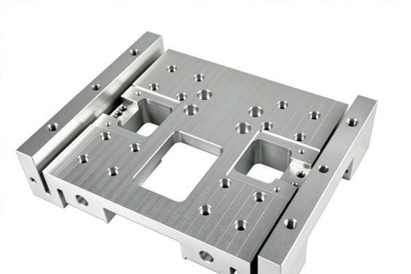
Structural components and tooling mainly provide fixing, support, and auxiliary processing functions, and often contain multiple holes, surfaces, or complex profiles.
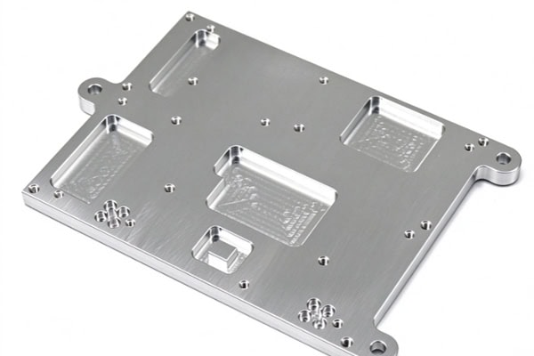
- Mounting Plates and Support Plates: Suitable for machining mounting holes, counterbores, slots, and weight-reduction structures.
- Clamps and Positioning Fixtures: Positioning areas are machined according to PCB dimensions and equipment movements.
- Protective Covers and Auxiliary Structural Parts: Cavities, interfaces, and mounting positions are machined according to the available equipment space.
Designing the machining solution according to the actual application of each part can reduce subsequent assembly adjustments.
How Can PCB Manufacturing Equipment OEM Parts Achieve Machining Accuracy?
PCB equipment components usually need to work together as a system, so machining should be controlled around datums, processes, and inspection requirements.
Confirm Drawings and Assembly Relationships Before Machining
Before OEM part production, manufacturing challenges should be identified based on 2D drawings, 3D models, and assembly relationships.
- Confirm Critical Datums: Clearly define mounting surfaces, locating surfaces, and major hole positions.
- Check Machining Accessibility: Determine in advance whether deep holes, deep slots, and complex side surfaces can be reached effectively by cutting tools.
- Plan the Clamping Method: Reduce positional errors caused by repeated setups.
Clarifying the machining plan in advance can reduce prototype rework and temporary adjustments during production.
Arrange Inspection Methods According to Part Functions
Inspection requirements vary among different components. Precision guide components and high-speed shafts also require attention to surface condition and material properties.
| Part Type | Common Materials | Key Control Items | Common Inspection Focus |
| Mounting Plates | Aluminum alloys, steel | Flatness, hole positions | Height, positional dimensions |
| Locating Blocks | Aluminum alloys, stainless steel | Locating dimensions, parallelism | Dimensions, geometric tolerances |
| Precision Guide Shafts | SUJ2, SUS440C, alloy steel, etc. | Diameter, roundness, hardness, surface roughness | Dimensions, hardness, surface quality |
| Shaft Transmission Parts | Alloy steel, stainless steel, etc. | Shaft diameter, concentricity, hardness, dynamic balance | Dimensions, geometric tolerances, dynamic balance |
| Precision Fixtures | Aluminum alloys, stainless steel | Positioning accuracy, repeatability | Overall dimensional inspection |
In addition to outer diameter dimensions, precision guide shafts and high-speed transmission shafts should be inspected for hardness, surface roughness, runout, or concentricity according to the drawings and application requirements.
Control Machining Deformation in Thin-Walled and Precision Parts
Lightweight structures, thin-walled parts, and large mounting plates in PCB equipment may be affected by material stress and clamping forces during machining.
- Leave an appropriate machining allowance during rough machining.
- Control dimensions through separate roughing and finishing stages.
- Use suitable support and clamping methods for thin-walled parts.
- Arrange appropriate stabilization treatment for high-precision structures according to material characteristics.
Proper control of machining deformation helps improve the dimensional condition of parts after assembly.
Properly Arrange Subsequent Processes for High-Precision Shafts
High-speed spindles, precision guide shafts, and some transmission shafts have high requirements for final dimensions and surface quality. After CNC turning completes the main profile, additional processes may still be required.
- Heat Treatment: Perform tempering, surface hardening, or other hardening processes according to material and design requirements.
- Cylindrical Grinding: Further control shaft diameter, roundness, straightness, and surface roughness.
- Surface Treatment: Some guide shafts may require treatments such as hard chrome plating according to application requirements.
- Dynamic Balancing: High-speed rotating shafts are balanced according to their rotational speed and structural requirements.
Proper coordination between machining and subsequent processes helps meet the performance requirements of precision motion components.
How Should Materials and Surface Treatments Be Selected for PCB Manufacturing Equipment OEM Parts?
Material selection should consider motion conditions, load, friction, operating environment, and machining requirements rather than being determined solely by material cost.
Match Materials to Part Functions
Different materials vary in strength, weight, wear resistance, and machinability. Aluminum alloys are suitable for certain lightweight structures, while stainless steel and alloy steel are suitable for high-strength, wear-resistant, or corrosion-resistant components. Bearing steels such as SUJ2 can be used for certain high-precision guide shafts, while engineering plastics such as POM are suitable for some low-friction, insulating, and light-load guide components.Properly matching materials with part functions helps control wear and dimensional changes during operation.
Plan Heat Treatment and Surface Treatment in Advance
The performance of precision motion components is closely related to heat treatment and surface condition, so these processes should be determined before machining.
- Bearing Steel and Alloy Steel: Perform tempering, quenching, or other heat treatments according to part requirements, followed by grinding to achieve critical dimensions.
- Stainless Steel Shafts: Determine the appropriate heat treatment condition according to the material and required properties.
- Aluminum Alloy Parts: Consider anodizing or hard anodizing according to wear resistance and corrosion resistance requirements.
- Precision Guide Surfaces: Focus on controlling hardness, surface roughness, and final dimensions.
Determining the process sequence in advance can reduce dimensional deviations caused by post-processing.
Reserve Post-Processing Allowance for Precision Fit Areas
Shafts and guide components may experience dimensional changes after heat treatment, coating, or grinding, so the machining allowance needs to be determined according to the final condition. Precision shaft diameters, guide surfaces, and mating holes should have clearly defined final dimensions, treatment thicknesses, and inspection requirements. Areas requiring grinding should not simply be machined to their final dimensions during the previous CNC process.Planning the final delivery condition in advance can reduce the risk of dimensional deviations after post-processing.
What Capabilities Should a PCB Manufacturing Equipment OEM Supplier Have?
When PCB equipment manufacturers select OEM part suppliers, they need to consider long-term project cooperation capabilities in addition to one-time machining capacity.
Ability to Handle Diverse Non-Standard Parts
PCB equipment development may involve structural adjustments and part version changes, so suppliers need strong engineering response capabilities.
- Support milling, turning, and multi-axis machining.
- Handle complex holes, slots, curved surfaces, and multi-sided structures.
- Support prototypes, small-batch production, and repeat production.
- Adjust machining solutions promptly according to drawing changes.
Flexible manufacturing capabilities can better accommodate equipment development and product iteration requirements.
Ability to Coordinate Processes for Precision Motion Components
OEM projects involving guide shafts, spindles, and transmission shafts require coordination among CNC machining, heat treatment, grinding, and surface treatment. From blank machining to final inspection, dimensional datums should remain properly coordinated throughout each stage. High-speed rotating components should also undergo dynamic balancing and related inspections as required.Complete process coordination can reduce dimensional deviations between different manufacturing stages.
Focus on Batch Consistency and Delivery Management
Once equipment enters mass production, customers pay greater attention to the stability of components across different batches. Suppliers need to maintain consistency in materials, machining programs, heat treatment conditions, critical dimensions, and inspection standards, while arranging delivery schedules and packaging according to project requirements.Stable batch management can reduce rework and waiting time during assembly.
Emphasize Drawing Confidentiality and Project Communication
OEM parts involve equipment-specific structures and design information. During cooperation, suppliers need to properly manage drawing versions, technical requirements, and change records.
- Drawing Versions: Ensure all parties use the latest drawing version and prevent outdated versions from entering production.
- Technical Requirements: Clearly define technical specifications and acceptance criteria to reduce misunderstandings.
- Change Records: Record and communicate design changes promptly to keep information consistent.
Standardized documentation and communication procedures can reduce the risk of production based on outdated drawings or misunderstood technical requirements, supporting long-term cooperation.
PCB manufacturing equipment OEM parts should be sourced based on part functions, with comprehensive consideration of materials, machining processes, heat treatment, surface treatment, inspection methods, and batch management. For structural components, dimensional and assembly requirements should be confirmed carefully; for precision shafts, hardness, surface roughness, and geometric accuracy should also be verified. TiRapid provides CNC precision OEM part machining services for PCB manufacturing equipment manufacturers, supporting customized production of precision shafts and complex structural components.
















