
Oil and gas monitoring equipment is used to collect data on pressure, temperature, flow, and gas composition. Component quality affects sensor positioning, equipment assembly, and field operation. In environments involving corrosive media, sour service, and potential explosion hazards, material selection, structural design, machining accuracy, and inspection requirements must be determined according to the equipment’s intended application. Defining these technical requirements in advance can reduce rework and procurement discrepancies while ensuring that manufactured parts meet actual operating conditions.
Common Components and Machining Requirements for Oil and Gas Monitoring Equipment
Different components serve different functions, so their critical dimensions and operating conditions should be identified before machining.
Equipment Housings and Mounting Structures
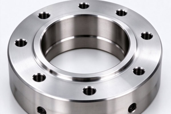
Housings, end covers, sensor mounting bases, and brackets protect internal components, position assemblies, and connect equipment. Housings and end covers require control of mounting-hole positions, connection dimensions, and mating surfaces to ensure proper assembly. Sensor mounting bases are designed around probe specifications and positioning methods, with bore diameters, hole spacing, and datum surfaces defined accordingly. If a housing uses a flameproof enclosure design, the length, gap, surface condition, and threaded structure of flamepaths must follow the approved design documentation rather than general housing machining practices. Critical dimensions must also be inspected after machining.
Fluid Connections and Functional Components
Fittings, flow-channel components, and sensor interfaces must meet connection, sealing, and internal cleanliness requirements. Thread specifications, sealing-groove dimensions, and flow-channel positions should be confirmed before machining. Small passages and intersecting holes require particular attention to burrs and residual chips. Components with pressure-containing or sealing functions should be inspected according to the design requirements. Clear specifications help reduce assembly problems and operational risks.
Material Selection and Machining Process Planning
Materials should be selected according to media composition, temperature, mechanical loads, and explosion-protection requirements. Machining processes should be planned around the component’s geometry and critical features.
Selecting Materials for Operating Conditions
Materials differ in corrosion resistance, strength, and machinability, so purchasing price should not be the sole selection criterion.
- 316L Stainless Steel: May be suitable for certain corrosion-resistant housings, fittings, and mounting components. Suitability must be verified against the service medium.
- Duplex Stainless Steel: Grades such as 2205 and 2507 may be considered for components requiring strength and resistance to localized corrosion.
- Nickel-Based Alloys: Can be evaluated for specific corrosive environments and elevated-temperature applications.
- Aluminum Alloys: May be used for selected lightweight structural components. For relevant parts installed in hazardous areas, applicable explosion-protection requirements concerning light-metal composition and mechanical-sparking risks must also be checked.
Metal parts in hydrogen sulfide environments should be checked for material category, heat treatment condition, and hardness limits in accordance with applicable requirements. Specific values depend on the material and service conditions, and a single hardness value cannot be used as a universal standard for all alloys.
Planning Machining Operations Around Component Geometry
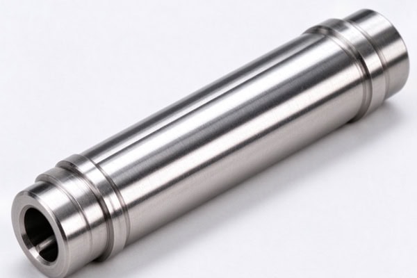
CNC machining can produce precision holes, mounting surfaces, and complex profiles. The process plan should be based on each component’s function.
- Milling and Drilling: Used to machine mounting surfaces, locating holes, and connection holes.
- Turning: Suitable for shafts, sleeves, and certain round fittings.
- Finishing and Deburring: Focuses on sealing surfaces, threads, flow passages, and precision mating areas specified in the design.
Thin-walled components also require consideration of clamping deformation and dimensional changes after machining. Structural dimensions and machining requirements for explosion-protection features must not be altered without design approval.
How to Control Component Accuracy and Quality
Inspection items should correspond to component functions and drawing requirements, with particular attention to features affecting assembly, explosion protection, and contact with process media.
Identifying Critical Dimensions and Inspection Methods
Different components require different inspection priorities. Measuring instruments and equipment should be selected according to the specified tolerances.
| Component Type | Critical Features | Inspection Focus |
| Equipment Housing | Overall dimensions, mounting-hole positions | Assembly fit |
| Flameproof Structural Components | Joint dimensions, gaps, and surface condition | Conformity with the approved design |
| Sensor Mounting Base | Locating holes, datum surfaces | Positioning accuracy |
| Fluid Fittings | Threads, sealing grooves | Connection and sealing-related dimensions |
| Flow-Channel Components | Passage dimensions, openings | Clear passages and residual burrs |
Coordinate measuring machines or optical measurement equipment may be used for complex positional relationships when required by the accuracy specifications. Records should be retained for critical explosion-protection dimensions so that machining results can be verified against the applicable acceptance criteria.
Controlling Surface Treatments and Cleanliness
Surface treatments can affect dimensions, corrosion resistance, and mating conditions. Treatment methods and acceptance criteria should therefore be defined in advance. For flameproof joints, the effects of coatings or other treatments on explosion protection must also be evaluated, and changes should not be made without approval.Components that contact the measured medium or contain internal passages should be cleaned to remove oil, chips, and other residues as required. Clear cleanliness criteria and inspection records help reduce the risk of contamination affecting equipment operation.
How to Select a Component Manufacturing Supplier
Supplier evaluation should cover machining capabilities, quality inspection, and technical communication rather than focusing solely on unit price.
Verify Machining Capabilities and Technical Requirements
Provide 2D drawings, 3D models, material grades, critical tolerances, and estimated quantities during quotation. This helps the supplier assess manufacturing feasibility. For flameproof housings, specify the relevant structural requirements. For components used in sour service, define the material specifications, heat-treatment conditions, and hardness acceptance criteria.
Confirm Quotation and Delivery Requirements
Material, inspection, and delivery requirements should be aligned before placing an order. Key items to confirm include:
- Material specifications and material certification requirements;
- Critical dimensions and surface-treatment standards;
- Required hardness records and inspection documentation;
- Packaging, acceptance criteria, and delivery lead times.
Clear technical documentation reduces repeated communication and helps buyers assess project costs and delivery risks more accurately.
Manufacturing components for oil and gas monitoring equipment requires material selection, machining accuracy, and quality acceptance to be coordinated according to actual operating conditions. Components related to explosion protection must also comply with the approved design and applicable standards. Providing complete drawings, material specifications, and acceptance requirements helps improve quotation accuracy and production coordination. TiRapid provides CNC precision machining and custom component manufacturing services, supporting prototype development and small-batch machining for oil and gas monitoring equipment projects.
















