
Multiaxis machining is a CNC manufacturing process that allows the cutting tool, workpiece, or both to move across multiple controlled axes during machining. Instead of only cutting from one fixed direction, a multi-axis setup can approach the part from different angles, making it easier to machine complex surfaces, angled holes, undercuts, deep cavities, and multi-face features with fewer setups.
This guide explains multiaxis machining, including its definition, working process, machine types, key components, advantages, limitations, common operations, and CNC applications.
What Is Multiaxis Machining?
Multiaxis machining is a CNC machining method that uses more than the standard three linear axes to cut complex parts from different angles. By adding rotary movement to the tool, workpiece, or machine table, the process allows the cutter to reach surfaces that would be difficult or inefficient to machine with traditional 3-axis machining.
In a standard 3-axis CNC machine, the cutting tool moves along X, Y, and Z directions. This is suitable for many simple parts, such as plates, pockets, slots, and flat surfaces. However, when a part includes angled faces, curved contours, side features, or deep areas with limited tool access, a 3-axis process may require several setups. Each setup adds time and may introduce positioning error.
Multiaxis machining solves this problem by adding rotary axes. These extra axes allow the tool or workpiece to tilt and rotate during machining. As a result, the cutter can maintain a better cutting angle, use shorter tools, reduce fixture changes, and produce more complex geometry in fewer operations. For precision CNC manufacturing, this makes multiaxis machining especially useful for aerospace, medical, robotics, automation, automotive, and complex prototype parts.
| Term | Meaning | Typical Use |
| Multiaxis machining | CNC machining with more than three controlled axes | Complex CNC parts and multi-side features |
| 3-axis machining | Linear X, Y, and Z movement | Simple parts, pockets, plates, and slots |
| 4-axis machining | Adds one rotary axis | Cylindrical features, indexed side machining |
| 5-axis machining | Adds two rotary axes | Complex surfaces and angled features |
| Multi axis cnc machine | CNC machine with linear and rotary axis control | Advanced precision manufacturing |
| Multi axis machining center | CNC machining center designed for multi-axis cutting | Complex milling, drilling, and contour machining |
Multiaxis Machining Vs. Traditional 3-Axis Machining
Multiaxis machining differs from traditional 3-axis machining because it adds rotary movement and better tool-angle control. A 3-axis machine moves in straight X, Y, and Z directions, while a multiaxis machine can rotate or tilt the part or tool to reach different sides and angles.
This does not mean 3-axis machining is outdated. For simple parts, 3-axis CNC milling is often faster, cheaper, and easier to program. Multiaxis machining becomes valuable when the geometry, tolerance relationship, surface finish, or setup reduction justifies the added complexity. The correct choice depends on part design, material, tolerance, production volume, and cost target.
| Comparison | 3-Axis Machining | Multiaxis Machining |
| Movement | X, Y, and Z linear axes | Linear axes plus rotary axes |
| Setup count | Often more setups | Usually fewer setups |
| Tool access | Limited to simpler approach angles | Better access to angled and hidden features |
| Programming | Easier | More complex |
| Best for | Simple prismatic parts | Complex surfaces and multi-side parts |
| Cost | Lower for simple parts | More efficient for complex parts |
| Accuracy risk | More reclamping error | Lower accumulated setup error |
How Does Multiaxis Machining Work?
Multiaxis machining works by combining CAD design, CAM programming, CNC machine setup, toolpath simulation, rotary axis control, cutting operation, and final inspection. The process starts with a digital part model and ends with a machined component produced through coordinated linear and rotary movement.
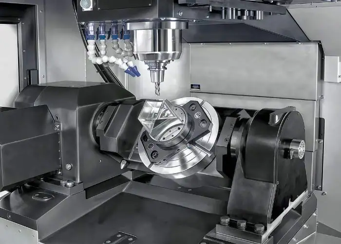
The workflow is similar to other CNC machining methods, but multiaxis machining requires more careful planning. The programmer must consider tool orientation, rotary axis limits, fixture clearance, machine travel, cutting direction, holder interference, and possible collision points. A toolpath that looks correct on the part model may still fail if the tool holder contacts the fixture or the rotary table exceeds its limit.
A well-planned multi-axis process can reduce the number of setups and improve feature alignment. However, the process only works well when the CAD model, CAM program, fixture, machine calibration, and inspection plan are all controlled. This is why multiaxis machining is not simply “more axes.” It is a complete manufacturing strategy for complex CNC parts.
| Step | What Happens | Why It Matters |
| Part design | Geometry and function are defined | Determines whether multiaxis machining is needed |
| CAD modeling | 3D model is prepared | Provides the machining reference |
| CAM programming | Toolpaths and axis movements are created | Controls cutter path and tool angle |
| Simulation | Toolpath is checked before cutting | Reduces collision and gouging risk |
| Setup | Part, fixture, tools, and offsets are prepared | Controls accuracy and stability |
| Machining | CNC machine removes material | Produces the required geometry |
| Inspection | Part is measured and verified | Confirms tolerance and surface quality |
Part Design And CAD Modeling
Part design and CAD modeling define what the CNC machine must produce. Before programming begins, engineers review the part geometry, tolerance requirements, surface finish needs, material, and critical features. This review helps determine whether the part can be made efficiently on a 3-axis machine or whether multiaxis machining will reduce setups and improve quality.
A good CAD model also helps identify difficult machining areas early. Deep cavities, angled holes, undercuts, thin walls, and curved surfaces may require special tool access. If these issues are understood during design review, the machinist or programmer can choose a better machining strategy instead of solving the problem after setup.
CAM Programming And Toolpath Generation
CAM programming converts the CAD model into CNC toolpaths. In multiaxis machining, CAM software must control not only where the cutter moves, but also how the tool is angled relative to the part surface. This makes toolpath generation more complex than basic 3-axis programming.
Software such as mastercam multiaxis is often used for advanced toolpath creation because it helps manage tool orientation, collision checking, rotary movement, and machine simulation. The programmer still plays a critical role. CAM software can calculate movement, but it cannot fully replace manufacturing judgment about tool selection, fixture design, cutting strategy, and inspection risk.
Machine Setup And Workholding
Machine setup and workholding determine whether the part can be machined accurately. A multi axis cnc machine may have excellent motion capability, but if the workpiece is not clamped properly, the final result can still fail. Workholding must resist cutting forces while allowing tool access from several directions.
This is more challenging than simple 3-axis clamping. In a multiaxis setup, the part may rotate or tilt during machining, so the fixture must avoid interference with the tool, spindle, holder, and table. The fixture must also support the part without causing deformation, especially for thin walls, long plates, soft materials, or high-value precision components.
Tool Movement, Rotary Axes, And Cutting Control
Tool movement in multiaxis machining combines linear and rotary axis control. The linear axes position the tool in X, Y, and Z directions, while rotary axes tilt or rotate the tool or workpiece. This coordinated movement allows the cutter to approach the surface from a more effective angle.
The advantage is not only access. Better tool orientation can reduce tool overhang, improve chip evacuation, lower vibration, and produce smoother surfaces. For curved or organic surfaces, the cutter can maintain a more consistent contact condition. This is especially useful when machining impellers, mold surfaces, medical components, aerospace structures, and complex housings.
Inspection And Final Part Validation
Inspection verifies whether the multiaxis machining process produced the required dimensions, surface finish, and geometry. For simple parts, basic measuring tools may be enough. For complex multiaxis parts, inspection may require CMM measurement, optical scanning, surface finish testing, custom gauges, or first-article inspection reports.
This step is important because complex parts can hide errors that are not visible by eye. An angled hole may look correct but be slightly off-position. A curved surface may appear smooth but fail profile tolerance. A multi-face feature may meet individual dimensions but fail alignment. Final validation confirms that the machining strategy, setup, and toolpath produced a functional part, not just a visually acceptable shape.
What Are The Main Components Of A Multiaxis CNC Machine?
The main components of a multiaxis CNC machine include linear axes, rotary axes, spindle, cutting tools, tool changer, workholding system, rotary table or tilting head, CNC controller, CAM software, coolant system, and machine structure. These components work together to control movement, rigidity, accuracy, tool access, and repeatability.
| Component | Function | Why It Matters |
| Linear axes | Move along X, Y, and Z | Basic positioning and cutting motion |
| Rotary axes | Rotate or tilt the part/tool | Enables angled and multi-side machining |
| Spindle | Holds and rotates cutting tools | Controls cutting power and precision |
| Tool changer | Switches tools automatically | Supports complex machining sequences |
| Workholding | Secures the part | Prevents movement and distortion |
| Rotary table | Rotates the workpiece | Supports 4-axis, 3+2, and 5-axis work |
| CNC controller | Coordinates machine movement | Controls accuracy and timing |
| CAM software | Generates toolpaths | Manages axis movement and collision risk |
Linear Axes And Rotary Axes
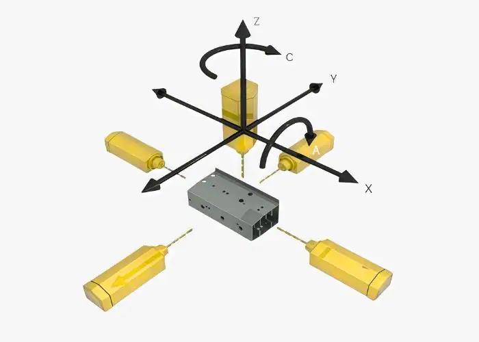
Linear axes are the X, Y, and Z movements used in almost all CNC milling machines. These axes move the tool or table in straight directions. Rotary axes add angular movement, often called A, B, or C axes depending on the direction of rotation. These rotary axes are what allow the machine to approach the part from more than one angle.
The combination of linear and rotary motion gives multiaxis machining its value. Instead of repeatedly removing the part from the fixture and reclamping it, the machine can rotate the part or tool to reach different faces. This improves feature relationship control and reduces manual handling. For precision components, that reduction in handling can be more important than the extra axis count itself.
Spindle, Tooling, And Tool Changer
The spindle provides the cutting power, speed, and stability needed to remove material. Tooling includes end mills, ball nose cutters, drills, reamers, chamfer tools, and specialty tools used for complex features. In multiaxis machining, tool length and holder shape are especially important because the tool may approach the part from different angles.
A tool changer allows the machine to complete multiple operations in one program. For example, one part may require rough milling, finish milling, drilling, tapping, chamfering, and surface finishing. Automatic tool changes reduce manual interruption and improve repeatability. However, each tool must be checked for reach, clearance, and deflection risk.
Workholding, Fixtures, And Rotary Tables
Workholding keeps the part stable during cutting. In multiaxis machining, the fixture must do two things at the same time: hold the part securely and leave enough open space for the tool to reach the required features. If the fixture blocks access, the machine cannot take full advantage of its rotary axes.
Rotary tables and tilting rotary tables allow the workpiece to rotate or tilt during machining. They are common in 4-axis, 3+2, and 5-axis setups. These systems help reduce the need for multiple setups and can improve alignment between features. However, they also require careful clearance planning because clamps, bolts, and fixture plates may become collision risks during rotation.
CNC Controller And CAM Software
The CNC controller executes the machine program and coordinates all axis movements. In multiaxis machining, this coordination is more complex because several axes may move at the same time. The controller must maintain smooth movement while following the programmed toolpath accurately.
CAM software creates the toolpath and helps the programmer verify movement before cutting. This is especially important for simultaneous 5-axis machining, where tool angle and contact position change continuously. The CAM system must match the machine configuration, because a toolpath that is safe on one machine may not be safe on another machine with a different table layout, rotary axis direction, or travel limit.
Machine Rigidity And Stability
Machine rigidity determines how well the machine resists vibration, deflection, and cutting force. In multiaxis machining, rigidity is critical because the tool may cut at different angles and with changing engagement. Weak rigidity can create chatter, poor surface finish, inconsistent dimensions, and shorter tool life.
Stability also affects production cost. If a machine is unstable, the shop may need slower feeds, lighter cuts, more inspection, or extra finishing passes. A stable multi axis machining center can produce complex parts more predictably, which is why machine quality matters as much as axis count.
What Are The Types Of Multiaxis CNC Machining?
The main types of multiaxis CNC machining include 3-axis, 4-axis, 5-axis, 3+2 axis, 6-axis, and advanced multi-axis configurations. The right type depends on part geometry, tolerance, surface finish, tool access, production volume, and whether the process needs fixed-position machining or continuous rotary movement.
| Type | Axis Movement | Best For | Main Limitation |
| 3-axis CNC machining | X, Y, Z | Simple parts, pockets, plates | Limited angled access |
| 4-axis CNC machining | X, Y, Z + one rotary axis | Cylindrical features, indexed machining | Less flexible than 5-axis |
| 5-axis CNC machining | X, Y, Z + two rotary axes | Complex surfaces and multi-face parts | Higher programming complexity |
| 3+2 axis machining | Fixed rotary positioning + 3-axis cutting | Angled features and reduced setups | Not continuous simultaneous cutting |
| 6-axis machining | Additional rotary or tool movement | Advanced complex parts | Higher cost and complexity |
| Multi-angle head machining | Tool head changes cutting angle | Deep or angled features | Requires careful setup planning |
3-Axis CNC Machining
3-axis CNC machining uses X, Y, and Z movement. It is the most common milling method and works well for many parts with simple geometry. Plates, blocks, brackets, pockets, slots, and flat surfaces can often be machined efficiently with 3-axis CNC milling.
Although 3-axis machining is not usually considered advanced multiaxis machining, it is the baseline for comparison. Many parts should remain on 3-axis machines if they do not require angled tool access. This keeps cost lower and programming simpler. The value of multiaxis machining becomes clear only when the part’s geometry exceeds what 3-axis machining can do efficiently.
4-Axis CNC Machining
4-axis CNC machining adds one rotary axis to the standard three linear axes. The rotary axis allows the workpiece to turn, which makes it easier to machine features around a part without reclamping. This is useful for cylindrical parts, side holes, wrapped features, and indexed machining.
A 4-axis setup can reduce several manual operations into one controlled program. For example, a component with holes on several sides may be rotated automatically instead of being manually repositioned. This can improve repeatability and reduce setup error. However, 4-axis machining still has less tool access than 5-axis machining, especially for complex curved surfaces.
5-Axis CNC Machining
5-axis CNC machining adds two rotary axes, allowing the tool or workpiece to tilt and rotate during machining. This gives the cutter access to complex surfaces and angled features that would be difficult with 3-axis or 4-axis machines. It is one of the most widely used advanced CNC methods for complex precision parts.
There are two common approaches: indexed 5-axis machining and simultaneous 5-axis machining. Indexed machining positions the part at a fixed angle before cutting. Simultaneous machining moves multiple axes during the cut. Indexed machining is often easier and more stable, while simultaneous machining is better for complex curved surfaces, blade-like parts, and continuous surface control.
3+2 Axis Machining
3+2 axis machining uses two rotary axes to position the part, then performs cutting with three linear axes. The rotary axes do not move continuously during the cutting pass. This method gives many benefits of multi-axis positioning without the full complexity of simultaneous 5-axis machining.
It is useful for angled holes, tilted surfaces, and features on multiple faces. For many CNC parts, 3+2 machining provides a practical balance between capability, cost, and programming difficulty. It can reduce setup count while keeping toolpaths more stable and easier to verify.
6-Axis And Advanced Multiaxis Machining
6-axis and advanced multiaxis machining systems provide additional movement beyond standard 5-axis machining. These systems may combine milling, turning, robotic movement, tilting heads, rotary tables, or special machine architectures. They are used when the part requires extreme access or when multiple operations are integrated into one machine.
These machines are not necessary for most CNC parts. Their value appears in highly specialized applications, such as complex aerospace components, advanced medical devices, turbine-related parts, and integrated mill-turn production. Because cost and programming complexity are higher, advanced multiaxis machining should be justified by part function, production efficiency, or quality requirements.
Rotary Table And Tilting Rotary Table Machining
Rotary table machining uses a table that rotates the workpiece around one axis. A tilting rotary table adds another angular movement, allowing the part to be positioned for better tool access. These systems are common in 4-axis, 3+2, and 5-axis machining centers.
The benefit is setup reduction. Instead of removing the part and placing it in a new fixture, the machine can rotate or tilt it under CNC control. This improves feature alignment and saves handling time. The challenge is that the fixture, table, clamps, and tool holder must all clear each other during movement.
How Does Multiaxis Machining Compare With Other CNC Methods?
Multiaxis machining differs from other CNC methods because it focuses on complex tool access, multi-directional cutting, and reduced setup changes. Compared with 3-axis machining, it handles more complex geometry. Compared with multi-spindle or Swiss-style machining, it is better suited for complex milled features rather than high-volume simple turned parts.
Multiaxis Machining Vs. 3-Axis Machining
Multiaxis machining provides better tool access than 3-axis machining. It allows the cutter to reach angled faces, side features, curved surfaces, and undercuts with fewer setups. This can improve feature alignment and reduce error caused by repeated reclamping.
However, 3-axis machining remains a better choice for many simple parts. If a component only has top-side pockets, flat faces, simple holes, and loose-to-moderate tolerances, 3-axis machining may be more cost-effective. The goal is not to use the most advanced process, but to use the most suitable process.
Multiaxis Machining Vs. Multi-Spindle Machining
Multi-spindle machining is designed for production efficiency, often in turning or repetitive part manufacturing. It can process multiple parts or multiple operations at the same time, which is valuable for high-volume production of simpler geometries.
Multiaxis machining focuses more on tool access and complex geometry. It is better suited for parts that need several angled surfaces, complex milling paths, or precise relationships between features on different faces. The two processes may both be advanced, but they solve different manufacturing problems.
Multiaxis Machining Vs. Swiss-Style Machining
Swiss-style machining is commonly used for small, precise, long, and slender components. It supports the workpiece close to the cutting tool, which helps control deflection during turning. It is widely used for medical, electronic, and precision mechanical components.
Multiaxis machining is usually more suitable for milled parts, housings, brackets, curved surfaces, and multi-face features. Some modern mill-turn machines combine turning and milling capabilities, but the process selection still depends on the main geometry. Long slender turned parts and complex milled parts usually require different strategies.
Multiaxis Machining Vs. Additive Manufacturing
Additive manufacturing builds parts layer by layer, while multiaxis machining removes material from a solid workpiece. Additive manufacturing can create internal channels or complex lightweight forms that may be difficult to machine directly. However, CNC machining often provides better dimensional accuracy, surface finish, and material consistency for many functional parts.
In some projects, both methods are used together. A part may be 3D printed or cast near-net-shape, then finished by multiaxis CNC machining to achieve tight tolerances, sealing surfaces, bearing features, or assembly interfaces. This hybrid approach can be useful when shape complexity and precision are both required.
What Are The Advantages Of Multiaxis Machining?
The main advantages of multiaxis machining are fewer setups, lower accumulated error, better tool access, improved surface finish, higher accuracy for complex parts, shorter lead time for suitable geometries, and greater design flexibility. It is especially valuable when a part has angled surfaces, curved profiles, deep cavities, or features on multiple faces.
Fewer Setups And Lower Accumulated Error
Fewer setups reduce accumulated error because the part does not need to be repeatedly removed, repositioned, and realigned. In conventional machining, a complex part may need several operations on different sides. Each time the part is moved, the datum relationship can shift slightly.
Multiaxis machining can reduce this risk by keeping the part in one controlled setup. This is important for features that must align across different faces, such as angled holes relative to a datum surface, side features relative to a bore, or multiple mounting points on a precision housing. Fewer setups also reduce operator handling time, which can improve lead time and consistency.
Better Accuracy For Complex Parts
Multiaxis machining improves accuracy for complex parts because it allows the cutter to approach features from more suitable angles. Instead of forcing the tool to reach deep or angled surfaces from one direction, the machine can rotate the part or tilt the tool to improve access.
This matters because accuracy is not only about machine positioning. It also depends on tool rigidity, cutting force, heat, vibration, and fixture stability. When multiaxis machining reduces tool length and improves cutter engagement, it can help produce more accurate and repeatable features, especially on parts with curved surfaces or multi-face relationships.
Improved Surface Finish
Surface finish can improve when the tool maintains a better cutting angle and uses shorter, more rigid tooling. Long tools may chatter or deflect, leaving marks on the surface. Multiaxis machining can reduce this problem by tilting the tool or part to keep the cutter in a more stable cutting position.
For curved surfaces, continuous or indexed axis control can also reduce step marks and improve surface consistency. This is valuable for parts such as medical implants, mold surfaces, impellers, aerospace structures, and precision housings where surface quality affects function, assembly, or appearance.
Greater Design Flexibility
Multiaxis machining gives engineers more freedom to design functional geometry. Angled holes, blended surfaces, lightweight structures, contoured faces, and multi-side features become more practical to manufacture. This is useful in industries where part performance depends on geometry, not only simple dimensions.
However, design flexibility still needs manufacturing judgment. Just because a machine can produce a shape does not mean the shape is economical. Good DFM review helps determine which complex features are necessary and which features can be simplified to reduce machining time and cost.
Faster Lead Time For Complex Geometries
Multiaxis machining can shorten lead time when it replaces several setups with one controlled process. Even if programming takes longer, the total production time may be lower because the part spends less time moving between fixtures, machines, and inspections.
This benefit is strongest for complex parts. A simple plate may not become faster on a 5-axis machine. But a housing with features on five faces, an aerospace bracket with angled surfaces, or a medical part with complex contours may benefit significantly from reduced setup and handling time.
What Are The Limitations Of Multiaxis Machining?
The main limitations of multiaxis machining are higher machine cost, more complex programming, greater setup risk, higher operator skill requirements, more demanding maintenance, and the need for careful simulation. It is a powerful process for complex parts, but it is not always the most economical choice for simple geometry.
Higher Machine And Setup Cost
Multiaxis machines are more expensive to purchase, operate, and maintain. The machine structure, rotary axes, controller, software, and calibration requirements all add cost. This is why parts made on multiaxis machines may have higher hourly rates than simple 3-axis parts.
Setup cost can also increase. Fixtures must provide access to multiple surfaces, avoid collisions, and hold the part securely during rotation or tilting. For low-complexity parts, these extra costs may not be justified. For complex parts, however, the reduction in setups and improved accuracy may offset the higher machine rate.
Complex Programming And CAM Requirements
Multiaxis programming is more complex because the toolpath must control position, angle, clearance, and axis movement. The programmer must think about the cutter, holder, spindle, fixture, part, and machine limits at the same time. This is very different from simple 2.5D pocketing or drilling.
CAM systems such as mastercam multiaxis help manage this complexity, but software alone does not guarantee a good process. The programmer must choose the right toolpath strategy, avoid unnecessary axis movement, control surface finish, and verify safe machine motion. Poor programming can create gouges, collisions, tool marks, or inaccurate surfaces.
Higher Skill Requirements
Multiaxis machining requires skilled programmers, setup technicians, and operators. They must understand axis directions, tool length, fixture clearance, cutting force, machine limits, and inspection requirements. A small mistake can be expensive because the parts are often high-value or difficult to remake.
Training and process control are therefore important. A shop that owns a multiaxis machine but lacks programming and inspection experience may not fully deliver the expected quality. For buyers, supplier capability should be evaluated by machine type, engineering experience, quality control, and past experience with similar parts.
Increased Risk Of Programming Or Setup Errors
More axis movement creates more possible error points. The tool may collide with a fixture, the holder may contact the part, the rotary table may exceed a safe angle, or the program may approach a surface incorrectly. These problems can damage the part, tool, machine, or fixture.
Simulation, dry runs, and setup verification are essential. Before cutting expensive material, the toolpath should be checked digitally and physically where appropriate. For high-value parts, first-article inspection should confirm that the process is stable before full production.
Machine Maintenance And Calibration Challenges
Multiaxis machines require careful maintenance and calibration because rotary axes must remain accurate. If a rotary axis is slightly out of calibration, features on different faces may not align correctly. This can cause tolerance issues that are difficult to detect during simple setup checks.
Regular maintenance helps protect accuracy. Machine condition, spindle performance, axis backlash, thermal stability, tool holders, probes, and rotary tables all affect final part quality. For precision multiaxis machining, machine health is part of the manufacturing process, not just a maintenance concern.
When Multiaxis Machining Is Not Necessary
Multiaxis machining is not necessary when a part has simple geometry, loose tolerances, easy tool access, or features that can be machined efficiently in one or two 3-axis setups. Using a multiaxis process for such parts may increase cost without improving function.
For example, a flat plate with holes and simple pockets may not need 5-axis machining. A basic bracket with only top-side features may be better suited to 3-axis milling. Multiaxis machining should be selected because it solves a real manufacturing problem, not because it sounds more advanced.
What Are Common Multiaxis Machining Operations?
Common multiaxis machining operations include complex surface milling, contour machining, angled hole drilling, undercut machining, multi-side milling, impeller machining, mold machining, and one-setup machining for complex CNC parts. These operations use coordinated tool and workpiece movement to reach surfaces that are difficult to machine with conventional methods.
Complex Surface Milling
Complex surface milling is used when a part has curved, blended, or freeform surfaces. These surfaces are difficult to machine with only vertical tool access because the tool may not maintain the best cutting angle across the entire shape. Multiaxis machining allows the tool to tilt and follow the surface more effectively.
This operation is common in aerospace components, medical implants, molds, turbines, impellers, and high-performance mechanical parts. The goal is not only to create the shape, but also to control surface finish, tool marks, and dimensional accuracy. A stable multiaxis toolpath can reduce secondary polishing or finishing in some applications.
Contour Machining
Contour machining follows complex profiles or edges on a part. In multiaxis machining, the tool can maintain better orientation along the contour, which helps reduce interference and improve cutting stability. This is useful when the contour is not easily accessible from one direction.
For example, a complex housing may have curved outer walls and angled mounting features. A 3-axis machine might need multiple setups or long tools to reach them. A multiaxis process can approach the contour from a better direction, reducing tool deflection and improving consistency.
Undercut And Angled Feature Machining
Undercuts and angled features are among the most common reasons to use multiaxis machining. These features are difficult because the cutter cannot reach them easily from a straight vertical position. A multi-axis machine can tilt the part or tool to create a direct approach path.
This reduces the need for special fixtures, custom angled setups, or secondary operations. It also improves accuracy because the part can remain in the same datum setup. For precision components, this can be critical when angled features must align with other surfaces or holes.
Hole Drilling At Multiple Angles
Multiaxis machining can drill holes at different angles without manually repositioning the workpiece. This is useful for manifolds, housings, brackets, aerospace structures, hydraulic components, and cooling-channel-related parts. Angled holes often require precise orientation, and manual setup can introduce error.
With a multiaxis process, the machine can rotate the part to the correct angle and drill the hole in a controlled position. This improves repeatability and reduces setup time. It also helps when multiple angled holes must be located relative to the same datum system.
One-Setup Machining For Complex CNC Parts
One-setup machining means completing more features while the part remains in the same fixture. This is one of the strongest advantages of multiaxis machining because it reduces datum transfer error. The fewer times a part is moved, the easier it is to maintain feature relationships.
This is especially useful for parts with tight tolerances across multiple faces. Examples include precision housings, aerospace brackets, automation components, robotic joints, and medical device parts. One-setup machining does not mean every part can be completed without any secondary operation, but it can significantly reduce process complexity.
What Are The CNC Applications Of Multiaxis Machining?
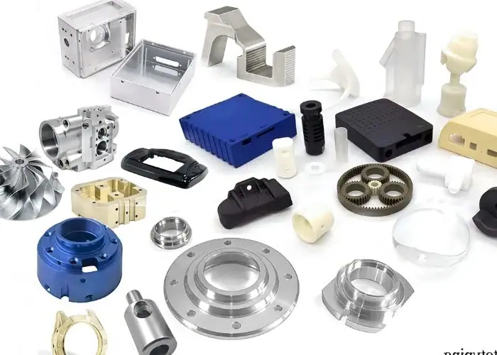
Multiaxis machining is used for CNC parts that require complex geometry, multi-face features, tight tolerances, angled holes, curved surfaces, or reduced setup error. Common applications include aerospace components, automotive parts, medical devices, robotics, automation equipment, defense components, marine parts, molds, and complex prototypes.
| Industry | Typical Parts | Why Multiaxis Machining Helps |
| Aerospace | Brackets, structural parts, impellers | Complex geometry and tight tolerance |
| Automotive | Housings, prototypes, performance parts | Multi-side features and repeatability |
| Medical | Implants, surgical tools, device parts | Complex surfaces and precision |
| Robotics | Joints, grippers, actuator parts | Compact geometry and alignment |
| Automation | Fixtures, machine components | Accuracy and repeatability |
| Defense | Precision equipment components | Reliability and complex features |
| Marine | Pump parts and curved components | Durable materials and shaped surfaces |
| Prototypes | Complex test parts | Faster design validation |
Aerospace And Aviation Components
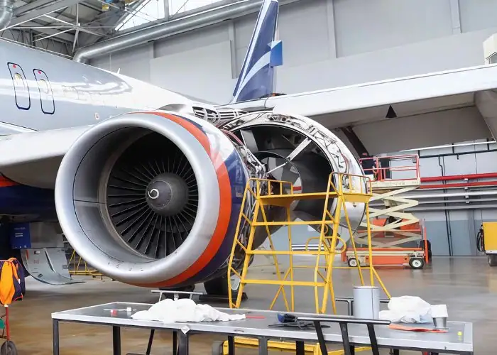
Aerospace components often require lightweight structures, complex pockets, curved surfaces, tight feature relationships, and high material removal from difficult materials. Multiaxis machining helps produce these features with fewer setups and better tool access.
Typical aerospace parts may include brackets, structural components, housings, turbine-related parts, impellers, and precision mounting features. These parts often require accurate relationships between several surfaces. Keeping more features in one setup helps reduce accumulated error and supports consistent inspection results.
Automotive Parts
Automotive applications include prototype housings, performance parts, powertrain components, suspension-related parts, fixtures, and complex brackets. Multiaxis machining is useful when these parts have angled faces, side features, or multiple functional surfaces that must align.
For automotive prototyping, multiaxis machining can also shorten development time. Engineers may need functional parts quickly for testing, fit checks, or design validation. A multiaxis process can reduce fixture changes and produce complex geometry faster than several separate machining operations.
Medical Devices And Surgical Components
Medical components often require complex geometry, smooth surfaces, and high dimensional control. Examples include implants, surgical instruments, device housings, orthopedic components, and custom medical fixtures. Many of these parts are small, complex, and made from difficult materials such as titanium or stainless steel.
Multiaxis machining is useful because it can maintain better tool access around organic shapes and angled features. It can also help reduce handling and setup error, which is important when parts require consistent quality and documented inspection. For medical-related components, surface finish and burr control are often as important as dimensional accuracy.
Robotics And Automation Parts
Robotics and automation components often combine compact design with complex functional geometry. Typical parts include robotic joints, grippers, actuator housings, sensor mounts, brackets, end-effectors, and custom fixtures. These parts may have features on several sides and require accurate assembly alignment.
Multiaxis machining helps produce these parts with fewer setups and better feature relationships. For example, a robotic joint may require holes, bearing seats, and mounting faces that must align accurately. If these features are machined in fewer setups, assembly accuracy and repeatability can improve.
Defense And Precision Equipment
Defense and precision equipment parts may require strong materials, tight tolerances, and reliable feature relationships. Multiaxis machining is useful for housings, mounting systems, optical components, communication equipment parts, and complex mechanical structures.
The advantage is controlled manufacturing. These parts often need not only accurate dimensions but also stable surfaces, repeatable assembly points, and reliable performance under demanding conditions. Multiaxis machining can support these requirements when part geometry is complex.
Marine And Industrial Components
Marine and industrial components may include pump parts, impeller-like features, valve components, mechanical housings, and structural parts made from durable materials. These parts often require curved surfaces, angled holes, or multi-face machining.
Multiaxis machining helps when strong materials and complex shapes must be combined. It can improve tool access and reduce setups, especially for parts that are difficult to hold or difficult to reach with standard milling.
Complex Prototypes And Low-Volume Production
Complex prototypes and low-volume parts often benefit from multiaxis machining because they may not justify expensive dedicated fixtures. A multi-axis process can machine more features in one flexible setup, which helps reduce tooling investment and lead time.
This is valuable for product development, engineering testing, and small-batch manufacturing. When the design is still changing, flexibility matters. Multiaxis machining can help produce accurate functional parts without committing to hard tooling too early.
How Do You Choose The Right Multiaxis Machining Method?
The right multiaxis machining method should be chosen based on part geometry, tolerance, material, surface finish, tool access, production volume, cost target, and whether continuous rotary movement is required. A simple part may only need 3-axis machining, while a complex multi-face part may justify 4-axis, 3+2, or 5-axis machining.
Understand Part Geometry And Tolerance Requirements
Part geometry is the first factor when choosing a multiaxis machining method. If all features are on one or two accessible faces, 3-axis machining may be enough. If the part has angled holes, side features, curved surfaces, or difficult undercuts, multi-axis capability may reduce setups and improve access.
Tolerance requirements also matter. If features on different faces must align precisely, machining them in fewer setups can improve accuracy. For example, a housing with a bore, mounting face, and angled side feature may benefit from multiaxis machining because all critical features can be tied more closely to the same datum setup.
Choose The Right Number Of Axes
The right number of axes depends on the part’s actual manufacturing needs. A 4-axis process may be enough for parts with cylindrical features or indexed side machining. A 3+2 process may be enough for angled faces or holes. A simultaneous 5-axis process may be needed for complex curved surfaces and continuous tool orientation.
Using more axes than necessary can increase cost without improving the final part. The correct approach is to identify the required tool access first, then choose the simplest machine configuration that can achieve the geometry, tolerance, and surface finish reliably.
Evaluate Machine Capability And Work Envelope
Machine capability includes spindle power, rotary axis accuracy, travel range, table size, tool changer capacity, controller performance, and machine rigidity. Work envelope determines whether the part, fixture, tool, and holder can move safely inside the machine.
This step is often overlooked. A part may appear suitable for multiaxis machining, but the actual machine may not have enough clearance for the fixture or tool holder. Before machining begins, the supplier should confirm that the workpiece can be reached safely from all required angles.
Consider Material, Tool Access, And Surface Finish
Material affects cutting force, heat, tool wear, and deformation. Aluminum, stainless steel, titanium, copper, plastics, and hardened materials all behave differently during machining. A good multiaxis strategy must consider how the material responds to tool engagement and axis movement.
Tool access and surface finish should also be reviewed together. A surface may be reachable with a long tool, but the finish may suffer because of deflection. Multiaxis machining can allow a shorter tool and better tool angle, which may improve both surface quality and dimensional consistency.
Balance Cost, Lead Time, And Part Complexity
Multiaxis machining can reduce lead time for complex parts, but it can increase cost for simple parts. The process should be justified by fewer setups, better accuracy, improved finish, or easier access to difficult features. If none of these benefits apply, a simpler CNC method may be better.
For buyers, this means cost should be evaluated at the part level, not only by machine hourly rate. A higher machine rate may still be economical if it reduces several setups, fixture changes, and inspection steps. The best quotation should reflect total manufacturing efficiency, not just machine type.
Decide When To Outsource Multiaxis CNC Machining
Outsourcing multiaxis CNC machining makes sense when the part requires machine capability, programming experience, inspection equipment, or material knowledge that is not available in-house. It can also help avoid the cost of buying and maintaining expensive equipment.
When choosing a supplier, review more than the machine list. Important factors include experience with similar parts, CAM programming capability, fixture design, inspection process, material knowledge, DFM feedback, and communication quality. A supplier with strong engineering support can often reduce risk before machining starts.
What Are The Future Trends In Multiaxis Machining?
Future trends in multiaxis machining include smarter CAM software, improved toolpath automation, better collision simulation, integrated probing, advanced inspection, automation-ready machining centers, and higher precision for complex CNC parts. These trends aim to reduce programming time, improve safety, increase repeatability, and make complex machining more efficient.
Smarter CAM And Automated Toolpath Generation
CAM software is becoming more intelligent, helping programmers generate safer and more efficient multiaxis toolpaths. Automated toolpath suggestions, collision checking, and tool-axis optimization can reduce programming time and improve consistency.
However, automation does not remove the need for engineering judgment. A CAM system may suggest a toolpath, but the programmer must still evaluate cutting force, fixture access, surface finish, tool deflection, and inspection requirements. The best results come from combining software capability with manufacturing experience.
Digital Simulation And Collision Detection
Digital simulation will continue to be central to multiaxis machining. As machines become more complex, simulation helps reduce the risk of tool crashes, fixture collisions, over-travel, and gouging. This is especially important when cutting expensive materials or high-value parts.
More accurate machine simulation can also improve quoting and process planning. If a shop can verify tool access and setup strategy before production, it can reduce uncertainty and provide more reliable lead times.
Higher Precision For Complex CNC Parts
Machine builders continue to improve rotary axis accuracy, thermal stability, spindle performance, and control systems. These improvements help multiaxis machining produce complex parts with better repeatability and surface quality.
Higher precision is especially important in aerospace, medical, robotics, and automation industries. These applications often require complex geometry and reliable assembly performance. As machine capability improves, more complex designs can be manufactured with better consistency.
Integration With Automation And Advanced Inspection
Multiaxis machining is increasingly connected with automation and inspection systems. Robotic loading, pallet systems, probing, tool monitoring, and CMM feedback can improve production efficiency and reduce manual error.
For production parts, this integration can help maintain consistency across batches. For prototypes and low-volume work, integrated inspection can provide faster feedback and reduce the risk of repeating the same machining error. The long-term trend is a more connected workflow from design to final inspection.
FAQs
What Is A Multiaxis Milling Machine?
A multiaxis milling machine is a CNC machine that moves the cutting tool or workpiece along more than the standard X, Y, and Z axes. A 4-axis machine adds one rotary axis, while a 5-axis machine adds two rotary axes. This allows the tool to reach angled surfaces, curved profiles, side features, and multi-face geometry with fewer setups. It is commonly used for aerospace, medical, robotics, automation, and complex precision CNC parts.
What Are Some Common Applications For Multiaxis Milling Machines?
Common applications for multiaxis milling machines include aerospace brackets, impellers, medical implants, surgical tools, automotive prototypes, robotic joints, automation fixtures, molds, housings, and precision components with angled holes or curved surfaces. These parts often require machining from multiple directions. Multiaxis machining reduces setup changes and improves feature alignment, making it useful when 3-axis machining would require several fixtures or secondary operations.
What Are The Advantages Of Using A Multiaxis Milling Machine?
The main advantages of using a multiaxis milling machine are fewer setups, improved accuracy, better access to complex features, shorter tools, better surface finish, and lower accumulated setup error. For example, a 5-axis setup can machine several sides of a part without reclamping. This improves datum control and may reduce lead time for complex CNC parts. The benefit is strongest when the part has angled surfaces, deep cavities, or tight feature relationships.
What Are The Disadvantages Of A Multiaxis Milling Machine?
The disadvantages of a multiaxis milling machine include higher machine cost, more complex programming, longer setup verification, higher operator skill requirements, and greater collision risk. A multi axis cnc machine price is usually higher than a standard 3-axis machine, which can increase hourly rates. For simple parts, multiaxis machining may not be cost-effective. It is best used when geometry, tolerance, or setup reduction justifies the added complexity.
Conclusion
Multiaxis machining is a powerful CNC manufacturing method for producing complex parts with fewer setups, better tool access, and improved feature accuracy. It is especially useful for components with angled features, curved surfaces, tight tolerances, and geometry that would be difficult or inefficient on a traditional 3-axis machine.
At TiRapid, we provide precision CNC machining and manufacturing services for custom metal and plastic components. Our team supports CNC milling, CNC turning, DFM analysis, material selection, surface finishing, and dimensional inspection to help customers produce accurate, stable, and manufacturable parts for real engineering applications.
















