The main spindle is one of the most important assemblies in a CNC machine. It provides the rotational motion required for cutting, holds either the cutting tool or the workpiece, and directly affects machining speed, torque, accuracy, surface finish, and process stability. A poorly matched or worn spindle can limit machine performance even when the CNC system and cutting tools are capable.
This guide explains how a main spindle works, its major components, common drive types, the differences between milling and lathe spindles, key performance specifications, selection factors, typical failures, and maintenance practices. It also shows how spindle performance influences machining quality and productivity.
What Is A Main Spindle In A CNC Machine?
A main spindle is the rotating assembly that provides the primary cutting motion in a CNC machine. In a milling machine, it rotates the cutting tool, in a lathe, it rotates the workpiece. Its speed, torque, rigidity, runout, and thermal behavior directly influence machining capability.
What The Main Spindle Does During CNC Machining
In CNC milling, the main spindle holds the toolholder and rotates end mills, drills, face mills, or other cutting tools. The spindle must maintain stable rotation while the machine axes position the cutter relative to the workpiece. Higher spindle stability allows the tool to cut more consistently under changing loads.
In turning, the main spindle grips the workpiece through a chuck or collet and rotates it while stationary or moving cutting tools remove material. The spindle therefore has to handle workpiece mass, clamping forces, radial loads, and axial cutting forces.
In both cases, the spindle must transmit power accurately without excessive vibration or deflection. The rotational motion may look simple, but the assembly combines mechanical, electrical, thermal, and control functions.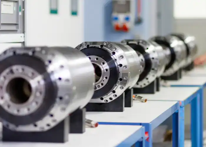
Why The Main Spindle Is Critical To Machining Performance
Spindle capability limits what a CNC machine can cut efficiently. A high-speed spindle is useful for small tools and aluminum machining, while heavy cutting of steel often requires more low-speed torque.
Rotational accuracy also affects the finished part. Excessive spindle runout causes the cutting edge to move off-center, which can reduce hole accuracy, increase tool wear, and leave uneven surface marks.
Thermal stability is equally important. As bearings and the motor generate heat, the spindle can expand and slightly change position. Well-designed cooling and bearing systems help keep this change predictable and controlled.
What Are The Main Components Of A CNC Machine Spindle?
A CNC machine spindle is not simply a rotating shaft. It normally includes a spindle shaft, bearings, drive system, motor, tool or workholding interface, lubrication, cooling, and position feedback components that work together as one precision assembly.
Spindle Shaft And Housing
The spindle shaft is the rotating structural element of the assembly. It transmits torque and supports the toolholder, chuck, or other interface at the working end.
The housing supports the spindle bearings and maintains the alignment of the complete assembly. Its stiffness is important because deformation can affect bearing geometry and tool position.
Both shaft and housing require high dimensional accuracy. Bearing seats, tapers, shoulders, and locating surfaces must remain concentric so that rotational errors are minimized.
Spindle Bearings And Preload
Spindle bearings support radial and axial cutting forces while allowing high-speed rotation. Precision angular-contact bearings are common in machining centers because they can support combined loads while maintaining high rotational accuracy.
Bearing preload removes internal clearance and increases spindle stiffness. Too little preload can reduce rigidity, while excessive preload increases heat and may shorten bearing life.
Bearing arrangement is therefore a major part of spindle design. High-speed milling and heavy-duty turning may require different bearing sizes, spacing, preload, and lubrication strategies.
Main Spindle Motor And Drive System
The main spindle motor supplies the energy required to rotate the spindle. Depending on machine design, the motor may drive the spindle through a belt, gears, a direct coupling, or be integrated into the spindle itself.
Motor characteristics influence available speed and torque. A spindle intended for large cutting tools may require strong low-speed torque, while a small high-speed machining spindle may prioritize RPM.
The motor and drive should be considered together with the cutting application rather than evaluated only by rated power.
Toolholder, Taper, Chuck, And Collet Interfaces
The spindle interface connects rotational motion to the cutting tool or workpiece. Milling machines commonly use standardized toolholder tapers, while lathes often use chucks or collets.
The interface must provide strong clamping and accurate concentricity. Dirt, wear, or damage at the spindle taper can increase tool runout even when the spindle bearings remain healthy.
Interface choice also affects tool size, maximum speed, rigidity, and automatic tool-changing capability.
Cooling, Lubrication, And Encoder Systems
Bearings and motors generate heat during operation, so spindle systems often use air, oil, grease, or liquid cooling depending on speed and design.
Lubrication reduces bearing friction and controls wear. Too much or too little lubricant can both create problems, especially in high-speed spindles.
Encoders provide speed, orientation, and position feedback to the CNC controller. This allows functions such as rigid tapping, spindle orientation, synchronized turning, and controlled tool changes.
How Does A Main Spindle Work?
The main spindle converts motor energy into controlled rotational motion while the bearings support cutting loads and the CNC system regulates speed and orientation. Reliable spindle operation depends on stable power transmission, precise bearing support, and accurate electronic feedback.
How Motor Power Is Converted Into Spindle Rotation
In a belt-driven system, the motor rotates a pulley connected to the spindle through a belt. This arrangement isolates some motor vibration and allows pulley ratios to modify speed and torque.
Gear-driven spindles use gears to change the rotational relationship between motor and spindle. This can increase low-speed torque for heavy cutting.
Direct-drive and built-in motor designs reduce intermediate transmission components. Their simpler power path can improve responsiveness and high-speed performance.
How Bearings Support Radial And Axial Cutting Loads
Cutting forces do not act in only one direction. Milling creates radial and axial loads that change as the cutter rotates, while turning can produce significant radial, axial, and moment loads depending on tool position.
The bearing set keeps the spindle centered while resisting these forces. Bearing spacing and preload contribute to the stiffness of the complete spindle.
If bearings wear or lose preload, the spindle can develop additional runout, vibration, heat, and noise. These changes can quickly become visible in machining results.
How The CNC System Controls Speed, Orientation, And Position
The CNC controller commands a target spindle speed based on the program. The drive system then adjusts motor output to maintain that speed under changing cutting loads.
For operations such as rigid tapping, the spindle must coordinate precisely with axis movement. The controller uses encoder feedback to synchronize rotation and feed.
Spindle orientation is also required for automatic tool changes and some turning operations. Accurate feedback therefore supports both cutting quality and machine automation.
What Are The Main Types Of CNC Spindles?
CNC spindles are commonly classified by how motor power reaches the spindle shaft. Belt-driven, gear-driven, direct-drive, and built-in motor spindles each offer different combinations of speed, torque, cost, vibration, maintenance, and thermal behavior.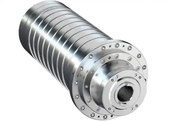
Belt-Driven Spindles
Belt-driven spindles connect the motor and spindle with a belt and pulley system. They are common because the design is relatively simple and cost-effective.
Different pulley ratios can provide useful flexibility between speed and torque. The belt can also absorb some vibration and protect the drive system from sudden shock loads.
The trade-off is that belts wear over time and can introduce heat, vibration, or speed limitations. Belt tension and condition therefore require routine maintenance.
Gear-Driven Spindles
Gear-driven systems use mechanical gearing to transmit power from the motor to the spindle.
Their main advantage is strong torque at low spindle speed, which makes them useful for heavy turning, large tools, and aggressive material removal.
However, gears increase complexity, noise, friction, and maintenance. At very high speeds, a geared system may also generate more heat and vibration than a direct design.
Direct-Drive Spindles
A direct-drive spindle connects the motor to the spindle with minimal transmission components.
This reduces backlash and can improve acceleration, responsiveness, and rotational smoothness. It is common in machining centers that need a balance of speed and accuracy.
Compared with geared systems, direct-drive designs may provide less torque multiplication at low speeds, so actual torque curves should be checked carefully.
Built-In Motor Spindles
In a built-in motor spindle, the motor rotor is integrated directly with the spindle shaft.
This design supports very high speeds because belts, gears, and separate couplings are eliminated. It also enables a compact spindle assembly with fast acceleration.
Thermal management becomes especially important because the motor generates heat inside the spindle structure. Effective cooling is necessary to protect bearing life and dimensional stability.
Belt Vs Gear Vs Direct Drive: Which Is Better?
There is no single best drive system. Belt drives offer practical cost and versatility, gear drives provide strong low-speed torque, and direct or built-in systems are attractive for speed and responsiveness.
The correct choice depends on the machining task. Heavy steel cutting usually demands different spindle characteristics from high-speed aluminum finishing.
Engineers should compare torque across the actual operating speed range instead of choosing only by maximum RPM or motor power.
CNC Milling Spindle Vs Lathe Main Spindle
A CNC milling spindle rotates the cutting tool, while a lathe main spindle rotates the workpiece. This difference changes the required interfaces, bearing loads, speed range, torque characteristics, and workholding design.
How A CNC Milling Spindle Rotates The Cutting Tool
A CNC milling spindle holds a toolholder inside a precision taper and rotates the cutting tool at the programmed speed.
The spindle must support a wide range of tools, from small drills to large face mills. Automatic machining centers also need accurate tool clamping and release for tool changes.
High rotational accuracy is especially important when small-diameter tools are used because even minor runout can create uneven cutting loads between tool flutes.
How The Main Spindle In A Lathe Machine Rotates The Workpiece
The main spindle in a lathe machine holds the workpiece through a chuck, collet, faceplate, or other workholding system.
The spindle must handle the mass and inertia of the rotating workpiece while resisting cutting forces. Large components can create much higher rotational loads than typical milling tools.
A lathe main spindle may also require accurate indexing or C-axis positioning when the machine includes live tooling.
Toolholder Tapers Vs Chucks And Collets
Milling spindle interfaces are optimized for accurately locating and clamping cutting tools. Common designs focus on rigidity, tool-change speed, and concentricity.
Lathe chucks are designed to grip external or internal workpiece surfaces. Collets provide higher concentricity for suitable round stock and smaller parts.
Each interface affects stiffness, runout, maximum RPM, and setup flexibility, so it should match both the machine and the application.
Speed, Torque, And Load Differences
CNC milling spindles often need higher RPM because milling cutters can be relatively small.
Lathe spindles may operate at lower speeds but require strong torque, especially when machining large diameters or making heavy cuts.
These are general trends rather than fixed rules. Small-part Swiss turning can use very high spindle speeds, while large milling cutters may need substantial torque.
What Main Spindle Specifications Matter Most?
The most important spindle specifications are not simply maximum speed and motor power. Engineers should also evaluate torque over the operating range, runout, bearing capacity, rigidity, thermal stability, interface size, and duty-cycle requirements.
Spindle Speed And RPM Range
Maximum RPM indicates how fast the spindle can rotate, but the useful range depends on tool diameter, workpiece material, and machining operation.
Small tools usually require higher RPM to achieve the correct cutting speed. Larger tools need less RPM and often demand more torque.
A broad usable speed range gives the machine more flexibility across roughing, drilling, and finishing operations.
Torque, Power, And The Torque-Speed Curve
Power and torque are related but should not be treated as the same specification.
Heavy cutting at low speed needs torque. High-speed machining may depend more on maintaining adequate power at elevated RPM.
The torque-speed curve shows how the spindle actually behaves across its operating range. This is more useful than a single peak torque or horsepower value.
Runout And Rotational Accuracy
Runout describes how far the rotating spindle or tool deviates from its ideal axis.
Excessive runout can enlarge holes, reduce surface consistency, and load individual cutter edges unevenly.
For small tools and precision finishing, low spindle runout is especially important because the error becomes large relative to tool diameter.
Bearing Capacity And Spindle Rigidity
Bearing size, type, arrangement, and spacing all influence spindle stiffness.
Greater rigidity helps resist cutting-force deflection and can reduce chatter during heavy machining.
However, a spindle designed only for maximum stiffness may not be suitable for very high speeds. Design involves balancing rigidity, speed, heat, and bearing life.
Thermal Stability And Cooling Performance
Heat changes spindle dimensions and bearing preload.
If spindle temperature rises unpredictably, tool position may shift and machining dimensions can drift during long production cycles.
A stable cooling system helps maintain repeatable spindle geometry. Thermal behavior is therefore particularly important for precision production.
Tool Interface And Maximum Tool Size
Spindle interface size affects the maximum practical tool diameter, rigidity, and torque capacity.
A compact taper suits high-speed work with smaller tools, while larger interfaces support heavier cutters and stronger cutting loads.
The interface should match the machine’s intended work rather than simply being as large as possible.
How Does Main Spindle Performance Affect CNC Machining?
Spindle performance influences dimensional accuracy, surface finish, tool life, material removal rate, and machining consistency. Problems in the spindle often appear first as changes in the finished part rather than as an obvious machine failure.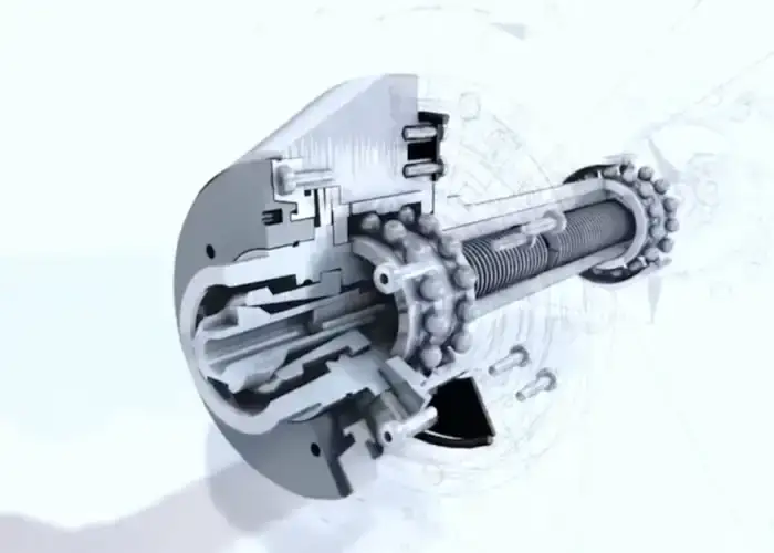
Dimensional Accuracy And Repeatability
Runout, thermal expansion, and bearing movement can all shift the cutting tool or rotating workpiece.
When these effects vary during production, dimensions may drift even if the CNC program does not change.
Stable spindle behavior helps maintain the same cutting relationship from the first component to later parts.
Surface Finish, Vibration, And Chatter
Chatter produces repeated marks on the surface and can reduce dimensional accuracy.
Spindle rigidity, bearing condition, toolholder quality, tool overhang, cutting parameters, and machine structure all influence vibration.
A healthy spindle cannot eliminate every source of chatter, but poor spindle condition can make stable cutting much harder.
Tool Life And Cutting Stability
Runout can cause one cutter flute to remove more material than the others. This creates uneven wear and can shorten tool life.
Bearing vibration and low rigidity can also create fluctuating cutting loads.
A stable spindle distributes cutting forces more consistently, allowing tools to operate closer to their intended cutting conditions.
Material Removal Rate And Cycle Time
Higher power and torque allow more aggressive material removal when the machine, tool, and workholding can support it.
High-speed spindles can reduce cycle time when using small tools and high-feed strategies.
However, maximum spindle output should not be used blindly. Productivity comes from balancing speed, torque, tool life, and part quality.
How to Choose the Right Main Spindle for CNC Machining
Selecting a main spindle requires matching spindle behavior to the actual cutting process. Material, tool diameter, operation type, accuracy, duty cycle, cooling, and production volume are more important than choosing the highest available RPM.
Match Spindle Speed to Material And Tool Diameter
Cutting speed requirements vary by material and tool.
Small cutters generally require higher spindle RPM, while large tools reach the same surface speed at lower RPM.
Aluminum and nonferrous materials often benefit from higher spindle speeds, while many steel applications place more emphasis on torque and rigidity.
Match Torque To Cutting Load And Machining Operation
Large drills, face mills, heavy roughing cutters, and turning operations can require substantial torque.
If the spindle produces adequate power only at high speed, it may struggle during low-speed heavy cutting.
The expected cutting operation should therefore be compared with the spindle torque curve rather than only the motor nameplate rating.
Select The Right Spindle Interface And Toolholding System
The spindle taper, chuck, or collet must support the size and type of tooling or workpiece required.
Large tools need enough interface rigidity to resist bending and torque.
For high-speed machining, balance quality and concentricity become increasingly important because small errors create larger centrifugal and cutting effects.
Consider Accuracy, Runout, And Bearing Requirements
High-precision parts and small tools require tighter runout control.
Heavy cuts require strong bearing support and good spindle rigidity.
The right spindle should satisfy both requirements without over-specifying performance that adds cost but provides little production benefit.
Evaluate Duty Cycle, Cooling, And Production Volume
A spindle used occasionally for prototypes faces different thermal demands from one running continuously in production.
High-duty-cycle machining requires reliable cooling and lubrication to maintain bearing and motor temperature.
Production applications should also consider maintenance access, replacement cost, and expected spindle life.
Balance Speed, Torque, Precision, And Cost
No spindle maximizes every characteristic without trade-offs.
High-speed designs may sacrifice some low-speed torque, while heavy-duty geared systems may not provide the smoothness or RPM required for high-speed finishing.
The most effective spindle is one matched to the machine’s dominant work rather than the most powerful or fastest model available.
What Are Common Main Spindle Problems?
Most spindle problems develop gradually through bearing wear, contamination, heat, collision loads, lubrication issues, or tool-interface damage. Early symptoms often include noise, vibration, temperature rise, poor surface finish, or increasing runout.
Excessive Runout And Loss of Accuracy
Runout can increase because of worn bearings, damaged tapers, contamination, or a bent spindle component.
The first signs may include inconsistent tool wear, oversized holes, or unstable finishing dimensions.
The spindle interface and toolholder should be checked before assuming the complete spindle requires replacement.
Bearing Noise, Wear, And Overheating
Bearing wear may produce unusual noise, vibration, or increasing operating temperature.
Excessive preload, poor lubrication, contamination, or collision loads can accelerate failure.
Continuing to operate a severely damaged bearing can damage the spindle shaft and housing, increasing repair cost.
Spindle Vibration And Chatter
Spindle vibration can come from bearings, imbalance, motor problems, drive belts, toolholders, or cutting conditions.
Diagnosis should therefore separate machine vibration from process-induced chatter.
Vibration monitoring can help identify changes before they become severe enough to damage parts or tools.
Tool Clamping And Taper Damage
Dirty or damaged spindle tapers reduce contact between the spindle and toolholder.
This can increase runout, reduce rigidity, and cause fretting marks.
Clamping-force problems can also allow the toolholder to move during cutting, creating both quality and safety risks.
Main Spindle Motor And Drive Problems
Motor faults may reduce power, cause unstable speed, or generate abnormal heat.
Belt-driven systems can suffer from worn belts or incorrect tension, while geared systems may develop gear wear or lubrication problems.
Electrical drive alarms should be investigated together with mechanical symptoms rather than treated separately.
Cooling and Lubrication Failures
Blocked cooling circuits or failed pumps can cause spindle temperature to rise.
Lubrication failure can rapidly damage bearings.
Monitoring coolant flow, lubricant delivery, and temperature helps detect these failures before a complete spindle breakdown occurs.
How To Maintain A CNC Machine Spindle
Spindle maintenance focuses on cleanliness, temperature, lubrication, tool interfaces, vibration, and avoiding unnecessary impact loads. Consistent monitoring can reveal gradual changes before they become expensive failures.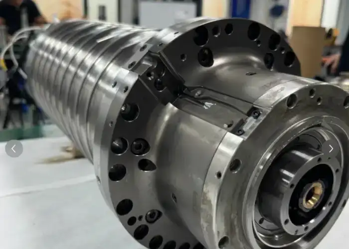
Monitor Temperature, Noise, And Vibration
Operators should become familiar with normal spindle sound and temperature.
A gradual increase in vibration, noise, or heat can indicate developing bearing or drive problems.
Tracking trends is more useful than waiting for a fixed alarm threshold after severe damage has already occurred.
Keep Spindle Tapers And Tool Interfaces Clean
Chips, oil residue, and dirt between the spindle taper and toolholder can reduce contact accuracy.
The taper should be cleaned regularly using methods that do not scratch the precision surface.
Toolholders should also be inspected because a damaged holder can make a healthy spindle appear inaccurate.
Maintain Lubrication And Cooling Systems
Bearing lubrication and spindle cooling should follow the machine manufacturer’s maintenance schedule.
Filters, oil levels, grease delivery, coolant flow, and pumps should be checked at appropriate intervals.
Stable lubrication and temperature control help extend bearing life and maintain machining accuracy.
Protect Bearings From Crash Loads And Contamination
Machine crashes can transfer large forces through the tool directly into spindle bearings.
Even if the spindle continues running, bearing damage or preload changes may remain.
After a significant collision, runout, noise, temperature, and vibration should be checked before returning the spindle to demanding production.
When To Repair, Rebuild, Or Replace The Main Spindle
Minor problems involving belts, sensors, cooling, or clamping systems may not require a complete spindle rebuild.
Bearing failure, severe runout, taper damage, or internal motor problems may justify rebuilding when the spindle design and machine value support it.
Replacement becomes more practical when repair cost, downtime, or repeated failures exceed the value of restoring the existing unit.
FAQs
Does A Higher Main Spindle Speed Always Improve CNC Machining?
No. Higher RPM is useful when the tool diameter and material require it, but heavy cutting may depend more on torque and rigidity. The correct spindle speed should match the cutting conditions.
What Is The Difference Between Spindle Power And Spindle Torque?
Power represents the rate of doing work, while torque represents rotational force. High-speed machining may rely heavily on power, while low-speed heavy cutting usually requires strong torque.
Can Spindle Runout Be Caused By The Toolholder Instead Of The Spindle?
Yes. Dirt, wear, poor balance, or damage in the toolholder can create apparent runout. The spindle taper, holder, cutting tool, and measurement setup should all be checked before diagnosing spindle failure.
How Long Does A CNC Main Spindle Last?
There is no fixed service life. Bearing quality, speed, duty cycle, lubrication, cooling, contamination, crashes, and cutting loads all affect spindle life. Condition monitoring is more useful than replacing a spindle according to a universal hour limit.
Conclusion
The main spindle determines how effectively a CNC machine converts motor power into controlled cutting motion. Speed, torque, runout, bearing stiffness, thermal stability, drive type, and tool interface all influence machining performance. The best spindle is not necessarily the fastest or most powerful one, it is the spindle whose characteristics match the material, tools, cutting load, accuracy requirements, and production cycle of the application.
At TiRapid, we provide precision CNC machining and manufacturing services for prototypes and production parts. Our machining team combines suitable equipment, stable tooling, controlled cutting parameters, and dimensional inspection to support accurate and repeatable components across aluminum, stainless steel, titanium, engineering plastics, and other materials.