Automation equipment relies on various mechanical components to perform positioning, clamping, transmission, and inspection tasks. Dimensional deviations, mismatched assembly interfaces, or insufficient structural rigidity can affect equipment stability. For equipment manufacturers, a CNC machining solution must balance component functionality, material properties, machining accuracy, lead times, and procurement costs. Defining critical dimensions and operating conditions in advance helps reduce assembly rework and ensures that components meet equipment design and production requirements.
Common CNC-Machined Components for Automation Equipment
Different components perform different functions, so machining priorities should be determined by their assembly relationships and operating loads.
Structural Supports and Mounting Components
These components secure equipment modules, connect mechanical structures, and provide stable mounting references.
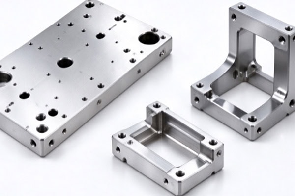
- Mounting Plates and Brackets: Control hole positions, mounting surfaces, and plate dimensions to ensure proper installation of motors, sensors, and other modules.
- Equipment Bases and Connectors: Determine structural thickness, connection methods, and critical fit dimensions according to load requirements.
- Protective Covers and Housings: Control overall dimensions, openings, and assembly clearances to prevent interference with moving parts.
Clear mounting references help reduce assembly adjustments and improve component compatibility.
Motion Transmission and Positioning Components
Moving components directly affect motion smoothness and repeatable positioning performance.
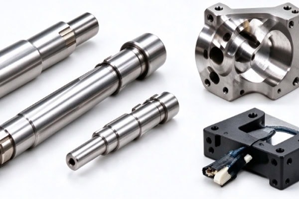
- Shafts and Connecting Sleeves: Control diameters, concentricity, and surface quality according to the required fit.
- Grippers and Locating Blocks: Account for clamping positions, contact geometry, and repeatable positioning requirements.
- Sensor Mounts: Maintain the mounting-hole positions and sensing directions specified by the equipment design.
Components exposed to frequent movement or repeated clamping also require consideration of wear, loading, and maintenance needs. Evaluating actual operating conditions helps prevent problems that may be overlooked when focusing on individual dimensions alone.
Material Selection and CNC Machining Processes
Materials and machining methods influence component strength, weight, manufacturing difficulty, and service life. Selection should reflect the operating environment and structural requirements.
Select Materials According to Operating Conditions
Common materials serve different applications, and their specific grades and properties should be confirmed before production.
- Aluminum Alloys: Lightweight and readily machinable, making them suitable for mounting plates, brackets, housings, and selected moving structures.
- Stainless Steel: Suitable for components requiring strength or corrosion resistance, depending on the operating environment.
- Carbon Steel and Alloy Steel: Used for structural and transmission components that carry loads or require wear resistance. Heat treatment may also be necessary.
- Engineering Plastics: Suitable for guide blocks, insulating components, and selected low-friction parts. Material selection should account for loads, temperature, and contact conditions.
A harder or more expensive material is not necessarily the better choice. The priority is to meet the component’s functional requirements while balancing machining costs and performance.
Plan Machining Operations Around Component Geometry
The machining route should account for feature geometry, tool accessibility, workholding stability, and the sequence used to produce critical dimensions. Milling is suitable for flat surfaces, pockets, and complex contours. Turning is used for rotational components such as shafts and sleeves, while drilling and tapping produce mounting holes and threaded connections. Thin-walled parts and components requiring machining on multiple sides need appropriate workholding and operation sequencing to reduce deformation and repositioning errors.
Machining Accuracy and Quality Control
Component quality depends on more than appearance. Dimensional accuracy, fit relationships, and compatibility with actual assembly requirements are equally important.
Identify Critical Dimensions and Inspection Items
Acceptance priorities vary by component type, so engineering drawings should clearly specify the dimensions and tolerances that affect equipment functionality.
| Component Type | Critical Features | Primary Purpose |
| Mounting Plates and Brackets | Hole spacing, hole positions, mounting surfaces | Ensure module assembly |
| Shaft Components | Diameter, concentricity, surface quality | Meet fit and transmission requirements |
| Grippers and Locating Blocks | Positioning dimensions, contact surfaces | Improve clamping consistency |
| Sensor Mounts | Mounting-hole positions, datum relationships | Maintain sensing position |
| Equipment Housings | Overall dimensions, opening positions | Prevent assembly interference |
Inspection methods should match the specified tolerances and component geometry. For critical fits, inspection criteria should be agreed upon before machining to prevent disputes over measurement methods or acceptance requirements after delivery.
Control Surface Finishing and Assembly Risks
Surface treatments can affect dimensions, corrosion resistance, and contact conditions. The following considerations help reduce potential problems:
- Confirm the finishing process in advance and evaluate its effects on mating surfaces.
- Mark areas requiring special fit control or protection from surface treatment on the engineering drawings.
- Inspect delivered components for burrs, impact damage, and dimensional changes that could affect assembly or movement.
- Coordinate inspection criteria with machining requirements to reduce rework and communication costs.
Effective control of surface finishing helps ensure that components perform as intended.
How to Choose a CNC Machining Supplier for Automation Components
Supplier selection affects component compatibility, project schedules, and batch consistency. Buyers should evaluate technical communication, manufacturing capabilities, and delivery management.
Provide Complete Drawings and Machining Requirements
When requesting a quotation, prepare 2D engineering drawings, 3D models, material grades, order quantities, critical tolerances, and surface treatment requirements. For mating components, identify the corresponding assembly parts and critical interfaces so the supplier can assess potential manufacturing challenges. If the project is still in development, discuss prototype production, design changes, and small-batch requirements in advance to reduce delays and additional costs.
Confirm Inspection Methods and Delivery Arrangements
Before placing an order, align technical specifications and acceptance criteria, including material requirements, critical dimensional reports, packaging, and delivery schedules. For complex components or parts with tight tolerances, consider first-article inspection or dimensional inspection reports according to project needs. Clear purchasing requirements help both parties evaluate quotations accurately, control manufacturing risks, and prepare for repeat orders.
CNC manufacturing for automation equipment components requires coordination between structural design, material selection, machining processes, and quality inspection to achieve assembly compatibility, operational stability, and cost efficiency. TiRapid provides customized CNC machining services based on customer drawings, material specifications, and order quantities, supporting equipment manufacturers from prototype development through component production.