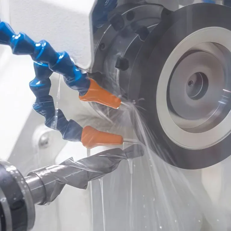
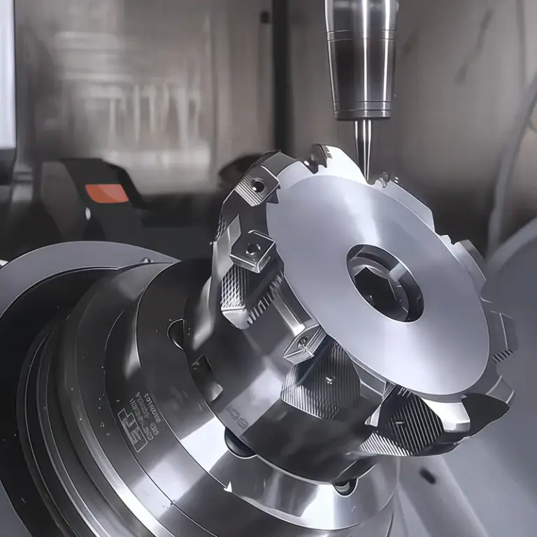
A bracket may need a curved edge to clear an adjacent component. A housing may require an accurately shaped internal wall, while a mold needs a continuous surface that defines the finished product. Profile milling produces these features by guiding a rotating cutter along a programmed contour.
For product engineers and buyers, understanding the process helps connect a drawing to a workable manufacturing plan. This guide explains the main methods, tools, applications, and design decisions, including what affects accuracy and what to specify when requesting a quote.
What Is Profile Milling?
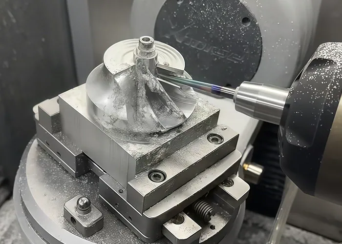
Profile milling is a machining operation that removes material along a defined contour to create or finish a part’s shape. It can produce external boundaries, internal walls, and curved surfaces. In CNC machining, coordinated machine movements position the cutter so its cutting edges generate the required geometry.
How the Cutter Follows the Geometry
CAM software calculates the cutter’s position relative to the required shape, accounting for its diameter and cutting geometry. During side cutting, the tool center follows a path offset from the finished boundary. The CAM system or machine control applies the appropriate cutter compensation.
That offset allows the cutting edge to generate the specified profile. An incorrect tool diameter or compensation setting can shift the finished wall away from its intended position.
Profile milling is an operation performed on a suitable milling machine. it does not always require a dedicated machine called a profile mill.
Profile Milling vs. Pocket Milling and Face Milling
These operations address different features and often appear in the same machining program.
| Operation | Main objective | Typical feature |
| Profile milling | Generate or finish a defined contour | Curved outer edge, internal wall, or sculpted surface |
| Pocket milling | Clear material inside a bounded region | Recess or cavity |
| Face milling | Produce a broad planar surface | Top face or reference surface |
For a housing, the shop might first face the blank, clear the cavity, and then finish its walls with a contour toolpath. Describing a feature as internal does not automatically make every operation on it pocket milling.
What Are the Main Types of Profile Milling?
A useful distinction is between planar contours, contours machined at different depths, and continuously varying surfaces. These are commonly described as 2D, 2.5D, and 3D work. Machine axis count is a separate consideration that depends on tool access and the orientations required.
2D and 2.5D Profile Milling
In a typical 2D contour operation, the cutter follows a planar outline at a selected depth. Repeating that contour at successive depths allows the machine to finish a taller wall or cut around a plate.
The term 2.5D commonly describes parts and strategies with planar features at different levels. Mounting plates, stepped brackets, and many enclosure features fall into this category. Their outlines can include curves without requiring a freeform surface toolpath.
3D Profile Milling
Three-dimensional profiling generates surfaces whose shape varies across the part, such as a mold insert or a blended transition. The toolpath must account for surface slope, local curvature, and the cutter’s contact point.
CAM strategies may follow successive height levels or traverse the surface in other patterns. Steep and shallow regions can benefit from different paths, because uniform spacing in the program does not necessarily produce uniform surface texture across changing slopes.
When Multi-Axis Machining Is Needed
A 3-axis machine can produce many curved surfaces when the tool can reach them from a fixed orientation. Additional rotary axes help when the cutter needs access to angled faces or when tilting improves clearance.
Indexed machining reorients the part between cutting operations. Simultaneous multi-axis machining changes the relative orientation during the cut. Either approach may reduce repositioning, but the choice should follow the geometry and setup requirements.
How Does the Profile Milling Process Work?
The process starts with the part geometry and acceptance requirements, then proceeds through programming, setup, material removal, and inspection. Roughing establishes the shape, while subsequent operations prepare and finish the required profile. The number of stages depends on the stock condition and the features being made.

Review the CAD Model and Plan the Toolpaths
The model defines nominal geometry. the drawing identifies dimensions, datums, tolerances, and surface requirements. Reviewing both helps the manufacturer distinguish functional interfaces from surfaces that have more design freedom.
The programmer chooses machining boundaries, entry and exit locations, and areas requiring smaller tools. Simulation helps identify collisions, uncut material, and unexpected moves before the program reaches the machine.
If a finish operation follows roughing, the program must preserve enough stock for cleanup without leaving heavy, uneven sections for the finishing cutter.
Select Tools and Set Up the Workpiece
Tool and fixture choices are developed together. The cutter needs clearance around the required contour, while the workpiece must remain supported throughout the operation.
External profiling deserves particular attention when it separates a part from its surrounding stock. The setup may use tabs, sacrificial stock, or another holding arrangement to retain the component safely until the cut is complete. Later operations must account for any material left for holding.
Rough, Semi-Finish, and Finish the Profile
Roughing removes excess material efficiently. Semi-finishing, where needed, refines the shape and evens out the remaining allowance. Rest machining uses a suitable smaller tool to remove material that a larger cutter could not reach.
Finishing brings the feature to its required dimensions and surface condition. Simple profiles may need only a roughing pass followed by finishing, while complex surfaces can require additional stages. Polishing or other finishing operations are specified separately when the milled surface does not meet the application requirement.
Deburr and Inspect the Finished Part
After machining, burrs are removed without damaging functional edges. The part is cleaned and checked against the drawing.
Inspection should follow the specified datum references and acceptance criteria. A visually smooth surface can still have the wrong shape, so appearance alone cannot establish whether a profile is acceptable.
Which Cutting Tools and Materials Are Used?
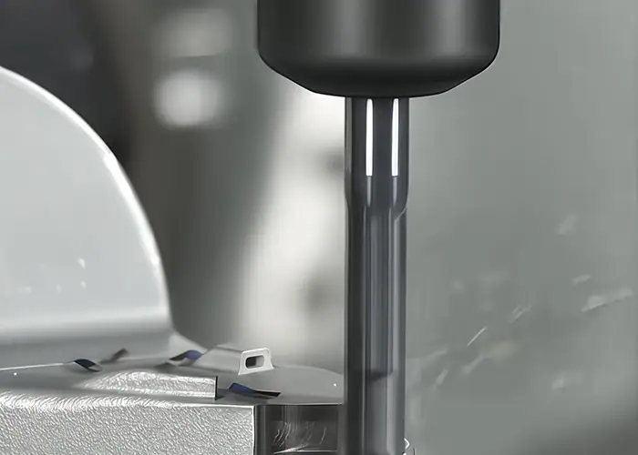
Flat end mills, ball nose end mills, and corner radius end mills cover many profiling tasks in metals and engineering plastics. Common workpiece materials include aluminum, steel, stainless steel, and titanium. The appropriate tool depends on the material grade, local geometry, and required reach.
Flat End Mills, Ball Nose End Mills, and Corner Radius End Mills
| Tool | Common use | Selection consideration |
| Flat end mill | Straight walls, planar outlines, and accessible steps | Diameter must fit internal radii and available space |
| Ball nose end mill | Blended surfaces and curved profiles | Contact position and pass spacing affect the finish |
| Corner radius end mill | Roughing and finishing compatible surfaces | Tool corner radius must suit the modeled geometry |
| Specialized undercut cutter | Recessed areas inaccessible to standard tools | Neck, shank, and holder clearance must be checked |
With a ball nose cutter, the cutting speed becomes very low near the tool center. Tool orientation and contact position therefore matter, especially during fine surface finishing. Selecting a ball nose cutter alone does not guarantee a smooth result.
Tool Diameter, Reach, and Cutting Geometry
A larger tool can offer greater rigidity, but it must fit the smallest feature it will machine. A smaller tool reaches tighter regions at the expense of stiffness and material-removal capacity.
Use only the reach needed for access. Long tools and unnecessary flute length can make the cutting system more flexible. Holder clearance must also be considered.a cutting edge that reaches the feature is insufficient if the holder collides with the part.
Material Considerations for Metals and Plastics
Aluminum alloys often allow productive milling, although chip adhesion and evacuation need attention. Steels and stainless steels require tooling and cutting conditions appropriate to their grade and condition. Titanium alloys place particular demands on heat management and cutting-edge durability.
Engineering plastics introduce different concerns, including clamping distortion, heat, and dimensional stability. Filled grades can also be abrasive. Material selection should begin with the part’s service requirements, followed by a machining plan suitable for the specified stock. Cooling, lubrication, and chip removal should match the material and tool. a single coolant practice is not suitable for every application.
What Affects Profile Milling Accuracy and Surface Finish?
Accuracy depends on the combined behavior of the machine, cutter, fixture, and workpiece. Surface finish also reflects cutting conditions and the spacing and direction of tool passes. Reliable results require control of these factors and a measurement method suited to the drawing.
Tool Deflection, Vibration, and Machine Motion
Cutting forces can bend the tool away from its intended position. Along a tall wall, this can produce taper or a changing dimensional error. Runout creates uneven loading between cutting edges, while vibration can leave visible patterns and accelerate wear.
Tool engagement often increases in an internal corner. A cut that runs smoothly along a straight section may become unstable as the cutter enters the radius. Adjusting the approach, engagement, or local feed can address that change in load.
Machine motion also matters at direction changes. Axis positioning errors and limitations in following a commanded path can affect the contour, particularly through tight transitions. Toolpath smoothing and suitable feed control help the machine follow the geometry without abrupt changes.
Workholding, Part Stiffness, and Thermal Effects
A thin wall may deflect during cutting and spring back afterward. A part can also measure correctly while clamped but move when released if the fixture has distorted it.
Machining sequence matters because removing material changes stiffness and may release residual stress. Temperature changes during production and measurement can further affect dimensions. The inspection setup should represent the specified acceptance condition, including any required restraint.
Cutting Parameters and Finishing Toolpaths
Feed, cutting speed, and engagement must suit the tool and material. Excessively light cutting can cause rubbing, while excessive loading increases forces and the risk of damage.
During surface finishing, adjacent passes leave small ridges called scallops. Their size depends on tool geometry, surface curvature, and path spacing. Reducing the spacing can improve the geometric finish, but it also increases machining time and cannot remove vibration caused by an unstable setup.
Climb and conventional milling change chip formation and force direction. Climb milling is commonly used in suitable CNC setups, but the choice also depends on machine condition, workholding, and the cutting situation.
Verifying Dimensions, Profiles, and Surface Quality
Dimensional measurements establish sizes and distances. Profile inspection evaluates the shape relative to its specified requirements, including datums where applicable. Surface roughness describes texture at a different scale. These checks answer different questions.
Accessible dimensions may be checked with appropriate gauges or measuring instruments. Complex profiles can require coordinate measurement or optical methods, while roughness needs a suitable surface-measurement method. Measurement uncertainty must be appropriate for the requirement being assessed.
TiRapid can control machining error within 0.01 mm on suitable features, with the applicable geometry and acceptance requirements established during drawing review. For a profile-critical part, identify the surfaces requiring this control and define how they will be measured.
Where Is Profile Milling Used?
Profile milling is used wherever a component needs a controlled outline or shaped surface. Typical applications include mold tooling, structural brackets, equipment housings, and precision fixtures. Its value comes from producing geometry that supports a specific fit, clearance, or forming function.
Mold and Die Surfaces
Mold inserts and die components may contain curved walls, blended transitions, and shaped surfaces that transfer geometry to another product. Milling establishes these features, with additional finishing selected according to the required surface condition.
An important planning issue is how adjoining regions meet. A smooth blend between surfaces may matter as much as the appearance of an individual toolpath area.
Aerospace and Automotive Components
Structural brackets and housings often combine shaped boundaries with mounting or locating features. Profiling creates clearance around neighboring components and forms contours specified by the structural design.
For lightweight parts, material removal can leave thin sections that need careful support. The manufacturing plan must preserve relationships between the finished contour and the interfaces used during assembly.
Automation, Medical, and Precision Equipment Parts
Automation equipment uses custom plates, grippers, and fixtures whose contours match the workpiece or surrounding mechanism. In precision instruments and medical equipment, shaped housings and component interfaces can serve similar fitting and clearance functions.
The application determines additional requirements such as material documentation, cleaning, or surface treatment. Those requirements should be included in the quotation, since producing the outline is only part of delivering the finished component.
What Are the Benefits and Limitations of Profile Milling?
Profile milling offers flexible shape generation and a repeatable programmed process. Its practical limits come from cutter access, local geometry, setup stability, and the work needed to meet the specification. Evaluating these conditions helps determine whether it is an economical manufacturing choice.
Flexible Geometry and Repeatable Production
Toolpaths can be updated when the design changes, which supports prototype development and custom components. Established programs and fixtures can also be reused for repeat production when the revision and manufacturing requirements remain unchanged.
Repeatability still depends on managing tool condition, offsets, stock variation, and inspection. Reusing a program does not eliminate process checks between batches.
Tool Access, Internal Corners, and Deep Features
A standard rotating end mill leaves a radius in an internal corner in the cutting plane. Reducing the radius requires a smaller cutter, which can make a deep feature harder to machine.
Some undercuts can be reached with specialized tools or another orientation. Fully obstructed regions may instead require a design change or another process. A functionally necessary internal sharp corner, for example, may call for EDM on a suitable conductive material, subject to access and geometry.
Programming, Machining Time, and Cost
Cost grows when features require extensive toolpath development, additional setups, or prolonged finishing. Small tools, hard-to-reach surfaces, and detailed inspection can also add work beyond what the part’s overall size suggests.
For a simple flat profile, laser or waterjet cutting may be worth comparing if their edge quality and dimensional capability meet the requirements. Milling becomes more relevant when the part also needs controlled walls, steps, machined interfaces, or curved surfaces.
How Can You Design and Specify Parts for Profile Milling?
Design for accessible cutting, stable support, and clearly defined functional requirements. Give the supplier enough information to evaluate the complete part, including finishing and inspection. Early clarification of difficult features helps avoid unnecessary machining work and quotation revisions.
Improve Tool Access and Support Thin Features
Allow generous internal radii where the assembly permits them. For an inside corner, leaving room beyond the selected cutter radius can make the change in engagement easier to manage. Agree on the actual radius during manufacturability review rather than selecting it in isolation.
Reduce unnecessary depth in narrow features and provide areas that can be held without damaging finished surfaces. If thin sections are essential, discuss temporary support or a machining sequence that retains surrounding material until later operations.
Consider a cover plate that must fit into a housing. A small relief at a nonfunctional corner may provide clearance for the mating part while allowing a more practical cutter. The designer should verify that the change preserves locating contact, sealing, and surrounding wall strength.
Specify Functional Tolerances and Surface Requirements
Identify which contours locate a mating part, provide clearance, or define a sealing boundary. Apply requirements according to those functions, using clear datum references and suitable general tolerances elsewhere.
If a coating or other treatment affects a critical fit, state whether the acceptance dimensions apply before or after that process. Specify edge breaks where needed so deburring does not alter a functional boundary.
For a visible surface, distinguish cosmetic expectations from measured roughness. A numerical texture requirement alone may not describe acceptable tool marks or their direction.
Prepare a Clear RFQ for TiRapid
A useful request for quotation includes:
- The current CAD model and drawing revision.
- Material grade and any required stock condition.
- Prototype, batch, or expected repeat-order quantities.
- Critical dimensions, datum references, and surface requirements.
- Surface treatment, inspection records, and delivery expectations.
Highlight areas where design changes are acceptable. TiRapid can then discuss the proposed machining approach against the requirements that must remain fixed. When comparing offers, check that each quotation covers the same drawing revision, finishing, and verification scope.
FAQs
Is Profile Milling the Same as Contour Milling?
The terms often overlap when describing machining along a defined shape. In CAM software, however, a command such as 2D Contour or 3D Contour identifies a specific strategy. Confirm the geometry and toolpath being discussed rather than relying on the name alone.
Can Profile Milling Produce Sharp Internal Corners?
A standard end mill cannot create a perfectly sharp internal corner in the cutting plane. Specify the largest radius the assembly permits, or discuss a corner relief or suitable secondary operation when the design requires a sharper feature.
Does Profile Milling Always Require a 5-Axis Machine?
No. A 3-axis machine can produce many planar contours and accessible curved surfaces. Additional axes become useful when they improve tool access, orientation, or the number of setups needed for the part.
Conclusion
Profile milling creates the boundaries and shaped surfaces that allow parts to fit, move, or form other products. Successful results depend on choosing tools and machining strategies that suit the geometry, then controlling and verifying the features that matter to the application.
For your next project, send TiRapid the model, drawing, and production requirements. A focused review of critical contours, surface requirements, and inspection needs provides a clear starting point for machining planning and a useful quotation.