
HDPE (High-Density Polyethylene) is a common thermoplastic with good impact resistance, chemical resistance, and low water absorption. It is therefore commonly used for mechanical equipment components, wear-resistant parts, guides, backing plates, protective panels, container components, and various non-metal structural parts. For HDPE parts that require rapid prototyping or small-batch production, CNC machining can directly perform cutting based on engineering drawings and CAD models without the need to manufacture injection molds. This makes it suitable for products with frequent dimensional changes or limited production quantities. However, although HDPE is easy to cut, this does not mean it can be machined directly using the same parameters as aluminum alloys or other metal materials. HDPE differs significantly from metals in terms of rigidity, thermal conductivity, and dimensional changes when exposed to heat.
During cutting, if chips are not removed promptly, plastic debris may repeatedly rub against the tool, causing localized temperature increases and resulting in tool sticking, melted edges, burrs, or reduced surface quality. When machining thin-walled parts, clamping force and cutting force may also cause slight deformation of the workpiece. Therefore, when using a CNC machine to machine HDPE, reasonable arrangements need to be made for material verification, tool selection, workpiece fixturing, cutting parameters, chip removal, and dimensional inspection. For HDPE workpieces with different thicknesses, grades, and structures, actual parameters also need to be adjusted according to machine rigidity, tool diameter, and machining paths rather than relying on fixed values alone.
What Preparations Are Needed Before Machining HDPE?
Confirm Material Condition and Part Requirements
HDPE is a type of polyethylene, but the actual sheets or rods used may have different grades, dimensions, and machining characteristics. After receiving the material, the material name, specifications, and machining direction should be confirmed, and the raw material should be inspected for obvious warping, scratches, or other defects. For parts with high precision requirements, the critical dimensions, tolerances, and assembly positions on the drawing should also be confirmed in advance. HDPE may undergo dimensional changes when exposed to heat and mechanical stress, so machining should not be based solely on the external shape of the part. It is also necessary to determine which dimensions are critical inspection dimensions.
Before machining, it is recommended to confirm:
- Whether the thickness and dimensions of the HDPE raw material meet the cutting requirements;
- Whether the part contains thin walls, deep grooves, or slender structures;
- Whether hole diameters, hole spacing, and mounting dimensions have clearly defined tolerances;
- Whether chamfers, fillets, threads, or other finishing operations are required.
The clearer the information, the easier it will be to control subsequent programming and machining.
Determine the Machining Method According to Part Structure
HDPE parts can generally be machined by CNC milling to produce features such as external contours, holes, grooves, steps, and curved surfaces. For HDPE shaft-type parts, CNC turning can also be used according to the required dimensions. If a part only contains simple planes and hole positions, three-axis CNC machining can generally meet the requirements. For parts with machining features in multiple directions, the number of setups can be reduced through re-fixturing or the use of multi-axis equipment. A complex structure does not necessarily mean that a high-axis-count machine must be used. The actual selection should be based on part dimensions, tolerances, tool accessibility, and production quantity.

What Tools Should Be Selected for HDPE?
Keep the Cutting Tool Sharp
During HDPE machining, tool edge condition has a significant effect on surface quality. A sharp tool can cut the material more directly and reduce friction between the tool and the workpiece surface. As the tool wears, cutting forces increase, and plastic chips are more likely to be pulled and adhere to the tool. Burrs may appear along the machined edges, and in severe cases, localized melting may occur. Carbide milling cutters are commonly considered for HDPE machining, with the appropriate number of flutes and flute geometry selected according to the part structure. For machining locations that require rapid chip evacuation, the tool should provide sufficient chip space.
How to Select the Number of Tool Flutes
The number of tool flutes affects chip space and feed per tooth. If the plastic chips generated during HDPE cutting accumulate in the flutes and cannot be removed promptly, friction and heat can increase. Therefore, tool selection should not be based solely on diameter. Flute geometry, helix direction, and machining position should also be considered. For deep grooves, cavities, and long-distance contour machining, particular attention should be paid to whether chips can leave the cutting area efficiently. Some plastic machining guidelines also emphasize maintaining good chip evacuation during HDPE machining and recommend determining suitable parameters for the specific combination of machine, tool, and material through trial cutting.
How Should Cutting Parameters Be Set for CNC Machining HDPE?
HDPE cutting parameters cannot be determined independently of the machine, tool, and part structure. A tool with the same diameter may require different spindle speeds and feed rates under different machine rigidity, cutting widths, and machining depths.
Spindle Speed and Feed Rate Need to Work Together
During HDPE machining, if the tool rotates at a high speed while the feed rate is too low, the tool may remain in contact with the material for too long, causing the temperature in the machining area to rise. Therefore, spindle speed should not simply be increased. Feed per tooth and the actual material removal rate also need to be considered. In actual machining, a relatively conservative cutting depth can first be used for trial cutting. The chip shape, workpiece edges, and machining sound can then be observed before gradually adjusting the feed rate and cutting amount.
Use Cutting Depths According to Part Rigidity
For solid HDPE blocks, a larger cutting amount can be used to improve material removal efficiency. For thin sheets, thin-walled structures, and slender parts, however, the cutting amount per pass should be reduced to minimize deformation caused by cutting forces. Roughing and finishing can also use different cutting conditions. Roughing mainly removes excess material, while finishing requires an appropriate amount of material to be left for a lighter final cut. For HDPE parts with high dimensional requirements, a small amount of finishing allowance can also be left after roughing, followed by finishing after the workpiece temperature has stabilized. This can reduce the influence of heat and cutting stress on the final dimensions. Relevant HDPE machining guidelines also recommend leaving an appropriate finishing allowance for precision parts and completing the final cut after the workpiece temperature has stabilized.
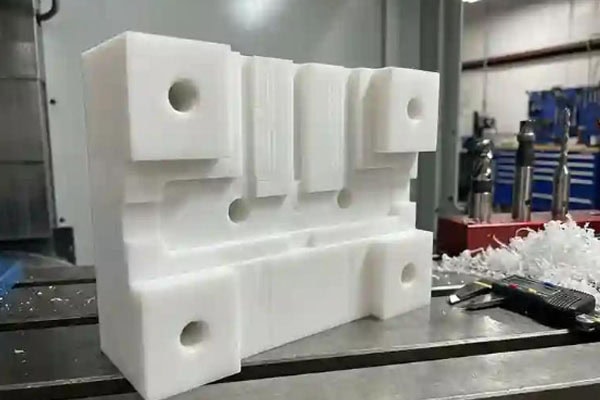
Why Are Chip Removal and Cooling Important When Machining HDPE?
HDPE machining produces chips with a certain degree of toughness, and relatively long plastic chips may form under some conditions. If these chips remain between the tool and workpiece, repeated cutting and friction may occur.
What Problems Can Poor Chip Evacuation Cause?
Poor chip evacuation may result in: plastic adhering to the tool surface; increased temperature in the machining area; burrs along workpiece edges; melted edges inside deep grooves and holes; and uneven surface machining marks.
Therefore, compressed air, chip extraction, or other methods can be used to remove chips from the cutting area promptly during machining. For parts with relatively deep grooves, it is particularly important to check whether the tool can effectively carry chips out of the cutting area. When machining HDPE, an appropriate air-cooling or other auxiliary method should be selected according to the specific machining equipment.
How Should HDPE Workpieces Be Fixtured to Reduce Deformation?
HDPE has relatively limited rigidity, especially when machining thin sheets, thin walls, and large-sized parts. If the clamping force is excessive, the workpiece may be compressed or bent during machining, and its dimensions may change after the fixture is released.
Secure the Workpiece Properly
Workpiece fixturing needs to ensure that the part does not move during machining while avoiding excessive localized pressure from the fixture. For thin sheets, the supporting area can be increased. For parts with high appearance requirements, soft contact surfaces can be used to reduce fixture marks on the workpiece surface. If the part has a relatively complex structure, clamping positions and machining sequences should also be planned in advance so that cutting forces are applied as much as possible to supported areas.
Machining Sequence Also Affects Dimensions
HDPE parts should not be machined by considering individual features alone. The machining sequence needs to be planned according to the overall structure. For example, for large plates, the main external profile can be completed first, followed by holes and local features. Thin-walled areas can then be finished after the main structure has become stable. This can reduce deformation caused by loss of support during machining.
Frequently Asked Questions
Why Does HDPE Melt During Machining?
HDPE melting is usually related to excessive temperature in the machining area. A tool that is not sharp enough, an excessively low feed rate, poor chip evacuation, or prolonged tool dwell in a local area can all increase frictional heat. When this occurs, the tool condition and cutting parameters should be checked, while chip evacuation should also be improved.
Why Does HDPE Develop Burrs During Machining?
HDPE has a certain degree of toughness. When cutting conditions are unsuitable, the material edge may not be cleanly cut and may instead be compressed by the tool, resulting in burrs. The tool sharpness, machining direction, and finishing allowance can be checked, and more suitable machining conditions can be confirmed through trial cutting.
Why Do HDPE Part Dimensions Change After Machining?
HDPE dimensions can be affected by temperature and mechanical stress. If significant heat is generated during machining or the clamping pressure is excessive, the workpiece may undergo some dimensional changes after machining is completed. For precision parts, the material can be machined at a stable temperature, while a finishing allowance can be retained after roughing.
How Can You Determine Whether CNC Machining Parameters for HDPE Are Suitable?
There is no single machining parameter that is suitable for all HDPE machining equipment. Different machines, tool diameters, numbers of flutes, material thicknesses, cutting widths, and part structures can all change the actual machining results.
Before production, a small amount of material can be used for trial cutting while observing: whether chips can be continuously evacuated; whether significant material adhesion occurs on the tool; whether burrs or melted edges appear along the machined edges; whether obvious tool marks are present on the part surface; and whether critical dimensions remain stable after machining.
If chips can be evacuated smoothly, there is no obvious material adhesion on the tool, and both edge quality and dimensions meet requirements, the parameters can then be applied to formal production with greater confidence. For precision HDPE parts, trial cutting and dimensional inspection are particularly important.
Conclusion
HDPE has good machinability, but its flexibility, dimensional changes caused by heat, and chip characteristics require appropriate tool conditions, cutting parameters, and workpiece fixturing during machining. After fully confirming the material and drawing requirements, the appropriate tools and fixturing methods should be selected according to the part structure, followed by trial cutting to confirm the cutting parameters. During machining, plastic chips need to be removed promptly to prevent excessive friction between the tool and workpiece. For thin-walled parts and large plates, clamping force and machining sequence also need to be controlled to reduce dimensional changes after machining. If an HDPE part requires high dimensional accuracy, the final dimensions should not be judged solely based on the theoretical dimensions in the CNC program. After roughing, actual measurements should be performed, and finishing should then be completed according to the measurement results to improve control of the final dimensions. Critical features such as hole positions, mating surfaces, and mounting surfaces should also be inspected according to the engineering drawings.
TiRapid provides CNC milling, CNC turning, five-axis CNC machining, and precision machining services, supporting different machining requirements from prototypes to production. For HDPE and other plastic parts, the actual machining solution still needs to be confirmed according to material specifications, part structure, dimensional tolerances, and production quantity. This helps maintain a suitable machining condition between the tools, equipment, and material while ensuring machining quality.
















