
Automation robots involve various types of components, including joints, end effectors, support structures, and mounting bases. Each component serves a different function and has different requirements for dimensional accuracy, material properties, and structural strength. For robot developers and equipment procurement teams, custom machining should not focus only on the machining cost of individual parts. Assembly compatibility, motion loads, machining difficulty, and future mass production requirements also need to be considered.
Which Automation Robot Parts Are Suitable for Custom Machining?
Robot equipment contains many non-standard structures, and standard components may not fully meet specific design requirements. Custom machining allows part dimensions and structures to be adjusted according to equipment space and functional requirements.
Joint and Connecting Components
Joint areas are related to the connection accuracy of multiple moving components, so machining needs to be planned around assembly requirements.
- Joint Connectors: Key dimensions such as shaft holes, mounting holes, and connecting surfaces need to be controlled to reduce assembly deviations.
- Flanges: Hole positions need to be designed according to the mounting method of motors or actuators to ensure accurate connections.
- Shaft Sleeves and Supports: The inner diameter, outer diameter, and concentricity should be controlled according to the fitting requirements of shaft components.
Stable dimensions in joint components can provide a more reliable assembly foundation for continuous robot movement.
End Effector and Fixture Components
End effectors directly perform gripping, handling, and positioning tasks, so their structures usually need to be customized according to the specific workpiece.
- Gripper Bases: Mounting positions and connection methods are determined according to cylinders, motors, or other drive structures.
- Fixture Base Plates: Locating holes, mounting holes, and clearance areas are designed according to the workpiece profile.
- Vacuum or Gripping Structures: Contact areas need to match the workpiece dimensions to prevent positional deviations during gripping.
Maintaining good dimensional compatibility between end components and workpieces can improve the stability of robot operations.
Common Parts and Machining Priorities
Different components perform different functions, so machining priorities can be determined based on application, loading conditions, and assembly requirements.
| Part Type | Common Materials | Key Machining Considerations |
| Joint Connectors | 6061, 7075 Aluminum Alloy, Steel | Hole Position, Concentricity, Rigidity |
| Flanges | Aluminum Alloy, Stainless Steel | Hole Spacing, Flatness, Position Accuracy |
| Gripper Bases | Aluminum Alloy, Steel | Mounting Dimensions, Hole Position |
| Robot Bases | Aluminum Alloy, Steel | Flatness, Load Capacity |
| Shaft Sleeves | Steel, Stainless Steel, Engineering Plastics | Inner/Outer Diameter, Concentricity, Wear Resistance |
| Precision Supports | Aluminum Alloy, Stainless Steel, Steel | Dimensional Accuracy, Perpendicularity |
Defining the function of each part before selecting materials and machining methods can help reduce the need for frequent structural modifications later.
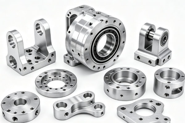
How Can Custom Automation Robot Parts Achieve Machining Accuracy?
Robots typically consist of multiple components that work together, and the dimensional relationships between hole positions, shaft centers, and mounting surfaces can directly affect assembly performance. Accuracy management before and after machining should therefore be incorporated into the customization process.
Conduct Drawing and DFM Reviews Before Custom Machining
Before drawings enter production, the structure should be reviewed from a manufacturing perspective to identify details that may affect machining.
- Confirm Critical Tolerances: Pay particular attention to shaft holes, mounting holes, locating surfaces, and mating dimensions.
- Analyze Thin Walls and Deep Cavities: Evaluate structural rigidity and tool access conditions to reduce the risk of machining deformation.
- Plan Machining Datums: Select suitable positioning and fixturing methods based on the final assembly requirements.
A thorough manufacturability analysis at the early stage can make design drawings more compatible with actual production conditions.
Select CNC Machining Methods According to Part Complexity
Robot components may contain curved surfaces, inclined surfaces, side holes, and irregular profiles. Equipment should be selected according to the geometric features of each part.
- 3-Axis CNC: Suitable for base plates, brackets, and standard connecting components.
- 4-Axis CNC: Suitable for structures with side holes and multi-directional machining features.
- 5-Axis CNC: Suitable for complex curved surfaces, multi-sided structures, and precision parts that require fewer repeated setups.
- CNC Turning: Suitable for rotary components such as shafts and sleeves.
Matching machining equipment with part geometry can reduce unnecessary repositioning and improve consistency during multi-sided machining.
Inspect Critical Dimensions After Machining
After production, core dimensions should be inspected according to the drawings. Hole diameters and hole spacing confirm the mounting relationships of motors, bearings, and connecting components. Concentricity and positional accuracy verify the mating features of rotating and moving mechanisms. Flatness and perpendicularity help ensure the connection between bases, flanges, and mounting surfaces. For complex or high-precision parts, CMM inspection can be used to measure critical dimensions. Complete dimensional inspection provides data for assembly verification and also makes it easier to track part quality.
How to Select Materials for Custom Automation Robot Parts?
Material selection should be based on robot load, operating speed, part dimensions, and working environment. Using the same material for all components is not suitable for every application.
Aluminum Alloys for Lightweight Structures
Robot moving components need to control their own weight, making aluminum alloys widely applicable to brackets, mounting plates, and connecting structures.
- 6061 Aluminum Alloy: Suitable for brackets, mounting plates, and general structural components, with good machinability.
- 7075 Aluminum Alloy: Suitable for parts requiring higher strength and stricter weight control.
- 6082 Aluminum Alloy: Can be used for equipment structures that need a balance between strength and machinability.
Proper use of aluminum alloys can achieve a more suitable balance between structural strength and moving weight.
Steel and Engineering Plastics for Specific Components
For parts exposed to higher loads or requiring low friction and wear resistance, materials can be selected according to actual operating conditions. Steel is suitable for high-load connectors, shafts, and wear-resistant structures. Stainless steel is suitable for corrosive environments. POM can be used for low-friction guide components and sliding structures. PEEK is suitable for specialized components requiring high temperature and wear resistance. Differentiating materials according to functional areas can help prevent mismatches between the design and actual working conditions.
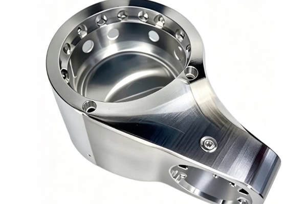
How to Select a Custom Automation Robot Parts Supplier?
Robot projects usually go through design, prototyping, assembly testing, and mass production. A supplier’s machining capabilities, engineering support, and delivery stability can all affect project progress.
Focus on Multi-Axis Machining and Complex Part Capabilities
When purchasing custom machining services, it is important to determine whether the supplier can handle the complex structures and precision machining features commonly found in robot components.
- 3-Axis, 4-Axis, and 5-Axis CNC: Cover structural parts with different levels of complexity.
- Precision CNC Milling: Suitable for machining holes, slots, curved surfaces, and complex profiles.
- CNC Turning: Meets the manufacturing requirements of rotary components such as shafts and sleeves.
- Thin-Wall Machining: Helps control machining deformation in lightweight components.
A comprehensive range of machining capabilities can reduce the communication costs caused by sourcing different components from multiple suppliers.
Focus on the Transition from Prototypes to Mass Production
During the robot development stage, parts may need to be adjusted based on assembly and testing results. A supplier’s responsiveness can affect the subsequent manufacturing schedule.
- DFM Analysis: Identifies potential conflicts between structural design and manufacturing processes before production.
- Rapid Prototyping: Helps engineering teams complete assembly verification and motion testing more quickly.
- Quality Inspection: Confirms machining results through dimensional data.
- Mass Production: Allows validated designs to move smoothly into subsequent orders.
Maintaining process continuity from drawing review through mass production can reduce the verification and communication costs associated with changing suppliers.
Custom automation robot parts require close attention to the match between part functions and manufacturing conditions. From structural design and material selection to machining methods and inspection standards, each aspect should be planned according to the specific application. TiRapid provides customized part machining support for robotics and automation companies, with services covering a one-stop manufacturing solution.
















