
When industrial equipment runs into trouble, the problem is often not a large component. It can be a shaft, a connection block, or a mounting plate with a dimensional deviation. These parts may look simple on their own, but once installed, even a small error can affect equipment performance. Custom machinery parts need to follow the drawing while also taking material, machining sequence, installation position, and operating conditions into account. CNC machining can handle complex dimensions and repeat production, but what really gives customers confidence is consistent quality from prototypes through batch production, without having to rework parts at the installation site.
Which Areas Are Most Likely to Cause Problems in CNC Machining Industrial Machinery Parts?
Industrial machinery parts come in many forms, including shafts, sleeves, supports, connectors, mounting bases, and custom-shaped components. During machining, it is not enough to focus only on overall dimensions. Some ordinary-looking holes, slots, and steps can determine whether a part fits properly or moves smoothly. Identifying these critical features before machining can save a lot of rework later.
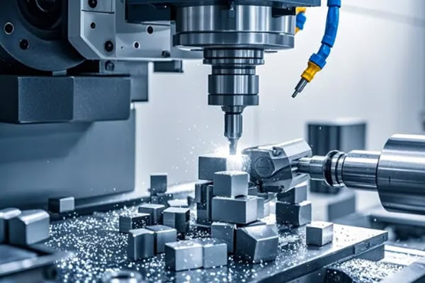
Holes, Slots, and Steps Need to Be Considered Together
A hole is not simply a feature that needs to be drilled. The distance between holes, the position relative to an edge, hole depth, and the relationship with surrounding steps can all affect assembly.
- Check the positional relationship of mounting holes: If one of several bolt holes is noticeably out of position, the part may require adjustment during installation.
- Pay attention to locating-hole fits: Excessive clearance can cause movement, while an overly tight fit can make assembly difficult.
- Plan deep holes in advance: When a hole is relatively deep, tool rigidity, chip evacuation, and toolpath design can all affect the quality of the hole wall.
- Consider internal and external features together: Shafts and sleeves often have both internal bores and external diameters. The dimensional relationship between them can matter more than either dimension by itself.
- Match slot width and depth to the mating component: Keyways, retaining slots, and mounting grooves that are not machined correctly can prevent related components from seating properly.
These dimensions are connected. What ultimately matters is whether the complete fit works as intended once the part is installed in the equipment, rather than whether a few individual numbers happen to fall within tolerance.
Thin-Wall Parts Should Not Be Clamped Too Aggressively
Guard plates, lightweight supports, and thin-wall connectors used in industrial equipment are often made from aluminum alloys or other lightweight materials. Excessive clamping force can deform the part during machining even when the change is not immediately visible. Once the part is released, the dimensions may shift.
- Reduce concentrated clamping force: Distribute pressure across more suitable contact areas to prevent localized deformation.
- Support thin-wall sections: Long unsupported areas are more likely to vibrate, so additional support may be needed.
- Avoid removing too much material in one roughing pass: Step-by-step material removal can help reduce dimensional changes caused by internal stress.
- Leave suitable stock for finishing: Final dimensions should not be reached too early; stable finishing conditions are important for accuracy.
Thin-wall parts have one particularly frustrating problem: they can measure correctly on the machine and change after removal. For these components, clamping, toolpaths, and machining allowance need to be planned together rather than relying on the final finishing pass to correct everything.
Complex Parts Require Equipment Capability to Be Checked First
Some industrial machinery parts are not especially large but require holes and surfaces to be machined from several directions. If the machine travel, tool length, or workholding space is insufficient, problems can appear after production has already started.
- Confirm the effective machine travel
- Check whether tools can reach deep slots and holes
- Verify that a reliable datum can be established after repositioning
- Check for possible interference between the fixture and workpiece
Different Materials and Part Structures Require Different CNC Machining Strategies
The same drawing may require different machining parameters when the material changes. Stainless steel tends to generate more heat, aluminum alloys require careful burr control, while alloy steels place greater demands on tool life and cutting stability. Industrial equipment parts are rarely identical in material and structure, so providing the exact material grade and operating conditions during quotation can make process and cost evaluation much more accurate.
Aluminum Parts Require Careful Burr and Surface Control
Aluminum alloys are generally efficient to machine, but their relatively soft structure can produce burrs around deep holes, narrow slots, and thin-wall sections. For equipment housings or mounting components with higher appearance requirements, handling and fixturing also need to protect finished surfaces from scratches.
- Choose tooling suitable for aluminum to reduce built-up material
- Control cutting parameters to prevent vibration in thin-wall sections
- Remove burrs around holes after machining
- Protect finished surfaces during part handling and transfer
Stainless Steel Parts Require Better Heat Control
Stainless steel is commonly used in equipment that requires corrosion resistance, but it can work-harden during machining. If the tool condition is poor, cutting becomes increasingly difficult, while surface quality and dimensional stability may also suffer.
Alloy Steel Parts Depend More on Tool and Process Stability
Alloy steel is often used for shafts, transmission components, and load-bearing structures that must withstand significant forces. In addition to dimensional accuracy, machining should account for tool wear, surface condition, and dimensional changes caused by subsequent heat treatment. If the drawing specifies heat-treatment hardness or surface treatment, these requirements should be confirmed before machining begins so the process sequence can be planned properly.
| Material | Machining Focus | Common Industrial Parts |
| Aluminum Alloy | Burrs, deformation, surface protection | Supports, housings, mounting plates |
| Stainless Steel | Heat, work hardening, tool wear | Fittings, connectors, machine bases |
| Carbon Steel | Dimensional stability, cutting efficiency | Bases, support components |
| Alloy Steel | Tool life, hardness, post-treatment deformation | Shafts, transmission parts |
| Brass | Surface quality, burr control | Sleeves, fittings |
How Should Custom Industrial Machinery Parts Move from Prototyping to Mass Production?
Many industrial equipment parts do not start with thousands of units. A small number of prototypes may be machined first, followed by equipment testing, dimensional adjustments, and eventually batch production. One common problem is that the prototype fits perfectly while production parts show dimensional differences. A stable CNC machining process should carry the validated critical dimensions and process conditions from the prototype stage into later production.
What Should Be Confirmed During Prototype Validation?
Perform actual assembly first: Whether the part installs smoothly is more informative than simply checking dimensions on an inspection table.
- Verify moving fits: For shafts, slides, sleeves, and similar components, check for binding or excessive clearance during actual operation.
- Check connection locations: Threads, mounting holes, and locating structures should be tested together with their mating components.
- Record dimensional changes: Once the prototype has been modified and approved, the final version should be clearly fixed to prevent outdated drawings from being used.
- Confirm surface treatment: Painting, anodizing, plating, and similar processes can change final dimensions and should be considered before machining is completed.
The Biggest Risk in Batch Production Is Constantly Changing the Process
If the same part uses different toolpaths, workholding methods, or machining datums for every order, variation between production batches can become more likely. A better approach is to stabilize the proven process after prototype approval and continuously sample critical dimensions. This makes it easier to maintain consistency even when an order is divided into several deliveries.
Inspection Should Not Happen Only at the End
Quality control for industrial machinery parts should not wait until every component has been completed. Critical dimensions can be checked at defined points during machining to detect tool wear or changes in machine condition early. Before shipment, key characteristics can then receive a final inspection.
| Inspection Item | What Is Checked | Customer Concern |
| Overall Dimensions | Length, width, diameter | Drawing compliance |
| Hole Locations | Diameter, spacing, position | Accurate assembly |
| Geometric Accuracy | Concentricity, flatness, perpendicularity | Stable operation and fit |
| Threads | Specification, depth, completeness | Smooth connection |
| Surface Condition | Roughness, burrs, scratches | Functional and appearance requirements |
What Should You Look for When Choosing a Supplier for Industrial Equipment Parts?
When sourcing custom parts, the lowest quotation does not always mean the lowest final cost. Repeated prototype changes, unstable batch dimensions, and additional rework can quickly consume the savings from a cheaper initial price. During quotation, it is useful to provide the 2D drawing, 3D model, material grade, quantity, critical tolerances, and surface treatment requirements so the supplier can evaluate the machining difficulty before discussing price and lead time.
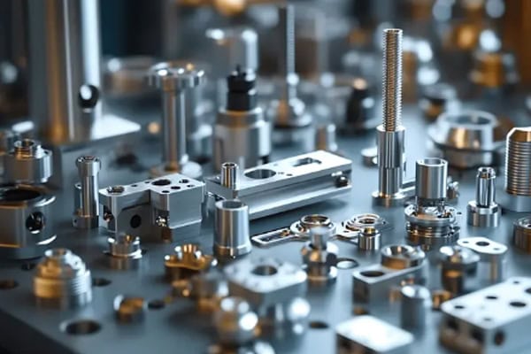
Similar Machining Experience Can Make Communication Much Easier
- Check whether the supplier has experience with similar machinery parts
- Confirm whether complex hole patterns and irregular structures can be handled
- Ask what equipment is used to inspect critical dimensions
- Confirm whether low-volume prototyping can transition smoothly into batch production
- Discuss heat treatment, surface treatment, and secondary machining in advance
More Complete Drawing Information Usually Leads to a More Reliable Quotation
With only a simple external profile drawing, it can be difficult for a supplier to accurately evaluate internal structures, fit tolerances, and machining challenges. A 3D model helps clarify the geometry, while the 2D drawing defines dimensions, tolerances, material, and surface requirements. Providing both makes technical communication much smoother.
CNC machining for industrial machinery parts is ultimately about closing the gap between a drawing and the actual equipment on the production floor: dimensions need to match, structures need to fit, and batch production needs to remain stable. Planning materials, critical tolerances, machining sequences, assembly validation, and inspection requirements early can significantly reduce rework later. TIRAPID provides custom CNC machining services for industrial equipment parts, supporting customers from prototype development through batch manufacturing.
















