
CNC Part Manufacturing: Process, Quality & Design Guide
CNC parts are used across aerospace, medical equipment, robotics, automotive systems, electronics, and industrial machinery because CNC machining can produce complex components with controlled dimensions and repeatable quality. However, reliable CNC part manufacturing involves much more than loading material into a machine. Design, material selection, tooling, workholding, machining strategy, finishing, and inspection all affect the final result.
This guide explains how CNC parts move from CAD design to finished components. It covers design considerations, common materials, machining processes, manufacturing steps, surface finishes, quality control, one-off and custom CNC parts, production costs, and how to evaluate a CNC parts manufacturer.
What Are CNC Parts?
CNC parts are components produced with computer numerical control machines that remove material according to programmed toolpaths. They can range from simple shafts and brackets to complex precision components with tight tolerances, multiple surfaces, and detailed geometric requirements.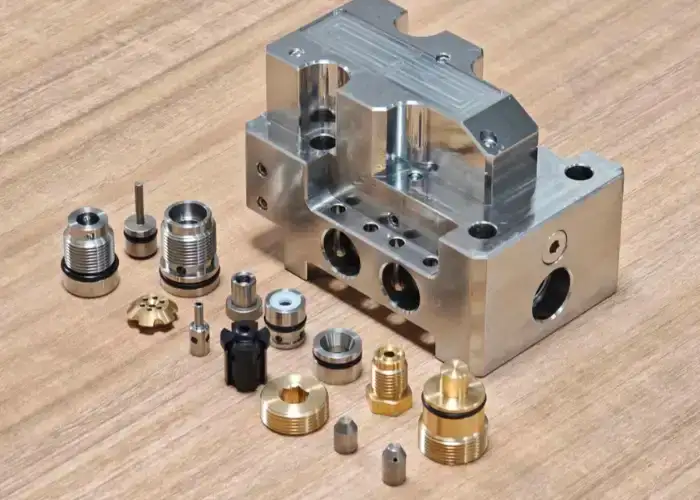
How CNC Parts Differ From Standard Machine Components
CNC parts are usually manufactured according to a specific drawing or CAD model. Their dimensions, material, tolerances, threads, surface finish, and other requirements are defined for a particular application rather than selected from a standard catalog.
By contrast, standard machine components such as bearings, fasteners, gears, and couplings are often available in predefined sizes. CNC machining becomes valuable when an existing standard component cannot meet the required geometry, interface, material, or operating condition.
This distinction also matters when sourcing. A supplier selling replacement machine parts is not necessarily a custom CNC parts manufacturer. Precision manufacturing requires programming, machining, inspection, and process-control capabilities.
What Makes a CNC Part a Precision Component?
A precision CNC part is defined by controlled dimensions and geometric relationships rather than simply by small size. Hole position, flatness, perpendicularity, concentricity, profile, and surface finish may all affect whether the part functions correctly.
For example, a housing can meet its outside dimensions but still fail assembly if bearing bores are not aligned. A shaft may have the correct diameter but fail if runout is excessive. Precision therefore involves controlling the relationship between multiple features.
Producing these parts requires suitable machines, stable workholding, correct cutting tools, controlled machining parameters, and inspection methods capable of verifying the specified tolerances.
When Custom CNC Parts Are Needed
Custom CNC parts are needed when standard components cannot provide the required geometry, material, accuracy, or performance. They are common in product development, automation systems, medical equipment, robotics, aerospace assemblies, and specialized industrial machinery.
CNC machining is especially useful because design changes can usually be implemented by modifying CAD data, CAM programs, or workholding instead of producing an entirely new mold.
This flexibility makes CNC machining suitable for prototypes, low-volume production, replacement components, and highly specialized parts.
How Does Part Design Affect CNC Machining?
Part design directly affects machining time, tool access, setup complexity, achievable tolerance, and overall cost. A design that considers CNC manufacturing from the beginning can often be produced faster, more accurately, and with fewer special tools or setups.
Tolerances and Critical Dimensions
Tighter tolerances require greater control over tooling, temperature, machine setup, and inspection. They may also require additional finishing passes or slower cutting conditions.
For this reason, strict tolerances should be applied mainly to features that influence function, fit, sealing, or alignment. Noncritical dimensions can usually use more practical tolerances without affecting product performance.
Engineering drawings should clearly identify which features are critical. This allows the CNC parts manufacturer to focus process control and inspection where they provide the most value.
Internal Corners, Radii, and Deep Pockets
CNC milling tools are round, so perfectly sharp internal corners cannot normally be produced with a standard end mill. Smaller internal radii require smaller cutters, which are less rigid and generally remove material more slowly.
Deep pockets create a similar problem because longer tools are needed to reach the bottom. Increased tool length raises the risk of vibration, deflection, and poor surface finish.
Using larger internal radii and avoiding unnecessary pocket depth allows stronger tools to be used. This can reduce machining time while improving dimensional stability.
Thin Walls and Part Rigidity
Thin walls are more likely to bend under cutting and clamping forces. Material removal can also release residual stress, causing the part to distort after machining.
Programmers may need to leave additional material during roughing and finish thin sections with lighter cuts. Workholding must also support the part without applying excessive clamping force.
If the application allows it, increasing wall thickness or adding structural ribs can make machining more stable and reduce production risk.
Holes, Threads, and Tool Accessibility
Standard hole sizes and thread specifications are generally easier and less expensive to manufacture because standard drills, taps, and gauges can be used.
Very deep holes, extremely small threads, or features close to tall walls can require special tooling. Tool access becomes even more important when several features must be machined from different directions.
Designers should consider not only whether a feature can be modeled, but whether a real cutting tool can reach and machine it effectively.
How Better Design Reduces Machining Setups
Every time a part must be removed and repositioned, additional setup time and positioning error can be introduced.
Designs that allow more features to be reached from one or two orientations can reduce both machining time and tolerance accumulation.
Multi-axis machining can also help, but the most economical solution is often a combination of good part design and an appropriate machine rather than using more complex equipment unnecessarily.
What Materials Are Commonly Used for CNC Parts?
CNC parts can be machined from aluminum, steel, stainless steel, brass, copper, titanium, and many engineering plastics. Material selection should balance strength, weight, corrosion resistance, temperature, electrical properties, machinability, and cost.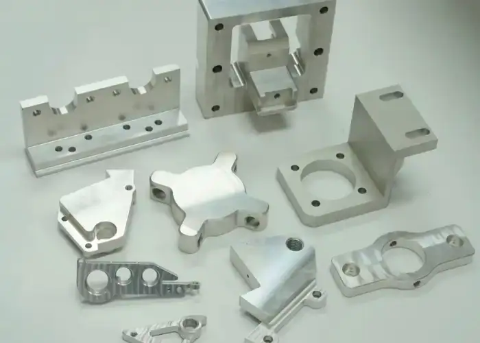
Aluminum CNC Parts
Aluminum is one of the most common CNC machining materials because it combines low density, good strength, corrosion resistance, and excellent machinability.
Aluminum CNC parts are widely used in aerospace, robotics, electronics, medical devices, automotive systems, and industrial equipment. Common grades such as 6061 are suitable for many structural and general-purpose applications.
Aluminum also supports anodizing, bead blasting, painting, and other finishes. Its relatively high machining speed makes it cost-effective for both prototypes and production parts.
Stainless Steel and Steel CNC Parts
Stainless steel is often selected when corrosion resistance, durability, and mechanical strength are important. It is commonly used in medical equipment, food-processing machinery, marine systems, and industrial assemblies.
Compared with aluminum, stainless steel normally requires lower cutting speeds and more attention to heat and tool wear. Some grades can also work-harden if cutting conditions are not controlled.
Carbon and alloy steels provide additional strength and hardness options. The appropriate grade depends on wear resistance, heat treatment requirements, welding needs, and service conditions.
Brass, Copper, and Titanium CNC Components
Brass offers good machinability and is frequently used for fittings, connectors, valves, and precision mechanical components. It can produce clean surfaces and detailed features efficiently.
Copper provides excellent electrical and thermal conductivity but requires careful cutting because some grades are relatively soft and ductile.
Titanium combines high strength, low density, and corrosion resistance. However, poor thermal conductivity concentrates heat around the cutting edge, increasing tool wear and machining time. It is therefore typically more expensive to machine than aluminum.
Engineering Plastic CNC Parts
POM, PEEK, PTFE, nylon, polycarbonate, and other engineering plastics can also be machined into accurate CNC parts.
Compared with metals, plastics require greater attention to cutting heat, clamping force, thermal expansion, and moisture behavior. Excessive heat or pressure can distort the component.
CNC machining plastics is particularly useful for functional prototypes, insulating components, fixtures, low-volume production, and applications that require chemical resistance or low friction.
How to Choose the Right Material for a CNC Part
Material selection should begin with actual operating requirements. Load, temperature, chemical exposure, weight, conductivity, wear, and environmental conditions should all be considered.
Machinability is also important. A high-performance material may increase tool wear and machining time even if the raw material price itself is not especially high.
The best material is therefore not automatically the strongest option. It should provide sufficient performance without adding unnecessary manufacturing difficulty or cost.
Which CNC Machining Processes Are Used for Parts?
The machining process depends mainly on part geometry. CNC milling handles prismatic and complex surfaces, CNC turning is efficient for rotational components, while drilling, threading, and multi-axis machining complete features that are difficult to produce with a single basic operation.
CNC Milling for Complex and Prismatic Parts
CNC milling uses rotating cutting tools to remove material from a stationary workpiece. It can produce flat surfaces, pockets, slots, holes, contours, and three-dimensional shapes.
Three-axis milling is suitable for many standard CNC parts. Four- and five-axis machines provide additional access to angled or multi-sided features.
Reducing repositioning can also improve feature-to-feature accuracy because more surfaces remain referenced to the same setup.
CNC Turning for Cylindrical Parts
CNC turning rotates the workpiece while a cutting tool shapes the outside or inside diameter. It is ideal for shafts, bushings, pins, spacers, threaded parts, and similar rotational components.
Modern lathes can also include live tooling for milling, drilling, and off-center features.
For suitable parts, combining turning and milling in one setup reduces handling and can improve alignment between features.
Drilling, Tapping, and Thread Machining
Drilling is used to create holes, while tapping forms internal threads. Thread milling is another option when larger diameters, difficult materials, or greater process control are involved.
Depth and accessibility matter. A shallow standard hole may be straightforward, while a small, deep hole may require special tools and careful chip evacuation.
Using standard hole diameters and thread specifications generally reduces machining cost and simplifies inspection.
Multi-Axis Machining for Complex CNC Components
Multi-axis machining allows the tool or workpiece orientation to change during machining, giving access to several surfaces without manual repositioning.
It is often used for aerospace components, medical parts, complex housings, impellers, and other geometrically demanding CNC components.
The main benefits are better access, fewer setups, and improved geometric relationships between features. However, programming and equipment costs are higher, so multi-axis machining should be used where it provides real manufacturing value.
When Multiple CNC Processes Are Combined
Many CNC parts cannot be produced efficiently with only one process. A turned component may require drilled cross-holes, milled flats, or threaded features.
Combining operations can reduce secondary setup time and improve consistency. Mill-turn machines are particularly useful when both rotational and prismatic features must be controlled together.
The process plan should be based on geometry and tolerance relationships rather than forcing the entire part onto a single machine type.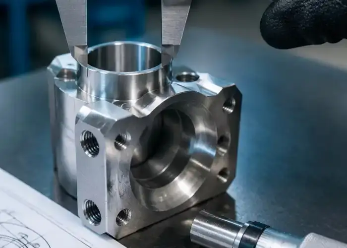
How Does the CNC Part Manufacturing Process Work?
CNC part manufacturing follows a controlled sequence from engineering review to final inspection. Each stage confirms that design, material, tooling, setup, machining, and quality requirements agree before production progresses.
Step 1: Review the CAD Model and Engineering Drawing
The manufacturer begins by reviewing the 3D model and technical drawing.
Critical dimensions, geometric tolerances, material, threads, surface finish, heat treatment, and finishing requirements are identified before programming starts.
Any ambiguous or difficult features should be clarified early because design questions discovered after machining begins can cause delays and rework.
Step 2: Confirm Material, Machine, and Manufacturing Strategy
The required material is confirmed, including grade, stock form, and dimensions.
A suitable machine is then selected according to part size, geometry, tolerance, and required axes.
The manufacturing strategy also considers whether the part needs several operations, multiple setups, or secondary processes.
Step 3: Plan Workholding, Datums, and Setups
Workholding must secure the part while keeping important surfaces accessible.
The machinist establishes datums so dimensions can be machined and inspected from consistent references.
For complex parts, setup planning is particularly important because each repositioning step can affect tolerance relationships.
Step 4: Select Cutting Tools and Generate Toolpaths
Cutting tools are selected according to the workpiece material, feature geometry, and required surface quality.
CAM software is then used to create roughing, semi-finishing, finishing, drilling, and threading operations.
The resulting toolpaths should minimize unnecessary movement while maintaining safe clearances and stable tool engagement.
Step 5: Machine and Inspect the First Part
The first part is produced under controlled conditions to verify the entire process.
Critical dimensions are measured using suitable inspection equipment. Tool wear, vibration, chip formation, and surface condition are also evaluated.
Small dimensional deviations may be corrected with tool offsets. Larger issues may require changes to the program, cutting parameters, or workholding.
Step 6: Adjust the Process and Run Production
Once the first part is approved, machining can move into production.
Tool-change intervals, inspection frequency, and offset correction rules may be standardized for repeat batches.
Process stability is important because temperature, tool wear, and material variation can gradually affect part dimensions.
Step 7: Apply Finishing and Complete Final Inspection
After machining, parts may require anodizing, plating, polishing, bead blasting, painting, or other finishing operations.
Critical dimensions may need to be rechecked after finishing because coatings can affect surface size and fit.
Final inspection confirms that the finished CNC parts meet drawing, cosmetic, and functional requirements before shipment.
What Surface Finishes Are Used for CNC Parts?
Surface finishing can improve corrosion resistance, wear performance, appearance, electrical behavior, or surface texture. The correct treatment depends on the base material, operating environment, dimensional requirements, and intended function of the CNC part.
As-Machined Finish
An as-machined surface retains the tool marks created during CNC cutting.
It is often suitable for internal components and functional prototypes where appearance is not critical.
Avoiding secondary finishing can reduce cost and lead time, especially when the machining surface already meets functional requirements.
Anodizing and Chemical Conversion Coating
Anodizing is commonly used on aluminum CNC parts to improve corrosion resistance and surface hardness while also providing decorative color options.
Chemical conversion coatings provide corrosion protection and can maintain electrical conductivity more effectively than conventional anodizing in certain applications.
Because coatings add measurable thickness, tight-fit dimensions should be considered during machining.
Bead Blasting and Polishing
Bead blasting creates a uniform matte texture and can reduce the visual appearance of minor machining marks.
Polishing produces a smoother or more reflective surface and may be used for cosmetic, cleaning, or friction-related requirements.
Both treatments can affect edges and dimensions if applied aggressively, so critical features should be protected when necessary.
Plating, Painting, and Powder Coating
Plating can improve wear, corrosion resistance, conductivity, or appearance depending on the coating material.
Painting and powder coating provide broad color options and environmental protection.
Coating thickness must be considered on threaded surfaces, mating fits, and other dimensionally sensitive areas.
How to Choose the Right Finish for a CNC Part
Finish selection should start with function rather than appearance alone.
Parts exposed to corrosion may require protective treatment, while sliding components may need wear or friction control.
For cosmetic parts, texture and color consistency may be more important. The chosen finish should always be compatible with the substrate and tolerance requirements.
What Determines CNC Part Quality?
CNC part quality depends on the complete process, including machine condition, cutting parameters, tool wear, workholding, material stability, finishing, and inspection. Reliable quality comes from controlling variation rather than relying only on the nominal accuracy of the machine.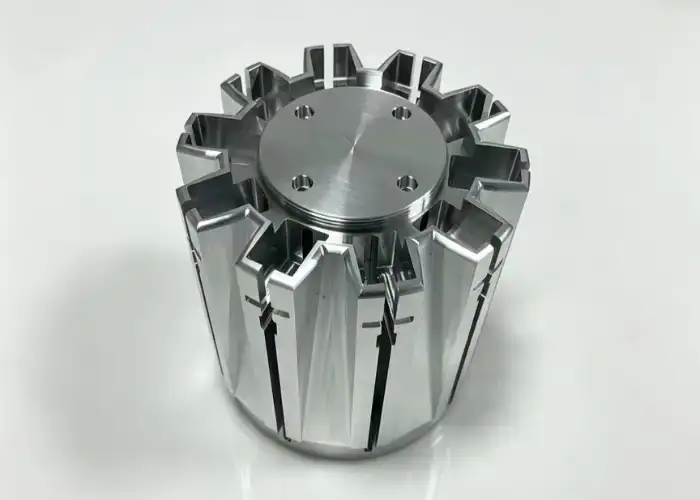
Dimensional Accuracy and Tolerance Control
Dimensional accuracy depends on machine positioning, cutting forces, temperature, tool condition, and setup.
Tight tolerances usually require more finishing passes and more detailed inspection.
A capable process should repeatedly produce dimensions inside tolerance rather than producing one correct part by adjustment alone.
Surface Finish and Burr Control
Surface quality is influenced by cutter condition, spindle speed, feed rate, stepover, toolpath direction, and machine rigidity.
Burrs can interfere with assembly, sealing, threads, and cosmetic appearance.
Deburring should remove unwanted edges without damaging critical dimensions or intentionally sharp features.
Tool Wear and Cutting Parameter Stability
As cutting tools wear, the effective cutting geometry changes.
This can gradually affect dimensions and surface finish even when the CNC program itself remains unchanged.
Production processes should therefore include tool-life monitoring and replacement criteria for critical operations.
Workholding and Setup Repeatability
The fixture must hold each part in a repeatable position while resisting cutting forces.
Excessive clamping can distort thin components, while insufficient clamping can allow movement or vibration.
Repeatable workholding becomes especially important when custom CNC parts are manufactured across several production batches.
First Article and In-Process Inspection
First article inspection verifies the initial production part before a larger batch continues.
During production, selected critical features can be measured periodically to detect dimensional trends.
This approach allows corrections before tool wear or process variation results in a full batch of nonconforming parts.
CMM, Surface Roughness, and Final Inspection
Complex geometric tolerances may require coordinate measuring machines, optical equipment, or specialized gauges.
Surface roughness can be measured when the drawing specifies a numerical finish requirement.
Final inspection combines dimensional verification with visual and documentation checks to confirm that the completed parts meet customer requirements.
Custom CNC Parts and One-Off CNC Parts
CNC machining is particularly suitable for custom and one-off production because parts can be manufactured directly from engineering data without dedicated molds. This allows designs to be tested, revised, and produced in small quantities with relatively low tooling commitment.
One-Off CNC Parts for Prototypes and Validation
One off CNC parts are commonly used for functional testing, assembly validation, engineering trials, and replacement applications.
Producing a single part in the intended final material allows engineers to evaluate real strength, fit, thermal behavior, and performance.
This provides more useful engineering feedback than a visual prototype when the component must perform mechanically.
Custom CNC Parts for Low-Volume Production
Low-volume CNC production is useful when demand does not justify injection molding, casting, or other dedicated tooling.
The same machining program can be reused across small batches, while fixtures can be improved as production becomes more stable.
This provides flexibility for products with changing demand or frequent design revisions.
Moving From Prototype to Repeat Production
After prototype approval, manufacturers can optimize toolpaths, fixtures, tooling, and inspection methods for repeat production.
Features that were expensive or unstable during prototype machining can also be reviewed before production volumes increase.
This transition helps reduce cycle time while preserving the approved dimensions and functional requirements.
When Dedicated Fixtures Become Cost-Effective
Simple prototypes can often use standard vises, soft jaws, or modular workholding.
As production quantity increases, dedicated fixtures may reduce loading time and improve positioning repeatability.
The fixture investment becomes worthwhile when the reduction in setup time and process variation offsets the initial cost.
What Affects CNC Part Manufacturing Cost?
CNC part cost is driven mainly by material, machining time, complexity, tolerance, setup requirements, finishing, quantity, and inspection. The lowest-cost design is usually the one that meets functional requirements without introducing unnecessary manufacturing difficulty.
Material Type and Stock Size
Material price affects cost directly, but machinability also matters.
Titanium may require slower cutting and more tool changes than aluminum, while oversized stock creates additional material removal.
Choosing stock dimensions close to the finished geometry can reduce both material waste and machining time.
Part Geometry and Machining Complexity
Complex features generally require more programming, smaller tools, slower cutting, or additional setups.
Deep pockets, thin walls, small radii, and difficult tool access are common cost drivers.
Simplifying noncritical geometry can often reduce machining time significantly.
Tolerance and Surface Finish Requirements
Tight tolerances may require additional passes, more frequent measurement, controlled environments, and higher-precision inspection equipment.
Very fine surface finishes can also increase machining and secondary processing time.
Specifications should therefore reflect actual functional needs.
Number of Setups and Tool Changes
Every setup adds machine downtime and introduces another positioning step.
Parts requiring machining from many directions generally cost more unless multi-axis equipment can reduce repositioning.
Reducing unnecessary tool changes can also improve cycle efficiency.
Production Quantity and Inspection Requirements
One-off CNC parts have higher setup cost per component because programming and preparation are spread across only one unit.
As quantity increases, setup cost is distributed over more parts, although tool wear and inspection requirements become more important.
Extensive inspection documentation can also add cost, especially when every dimension must be recorded.
How to Reduce Cost Without Sacrificing Part Quality
Cost reduction should focus on eliminating unnecessary manufacturing work rather than lowering functional quality.
Using practical tolerances, larger corner radii, standard threads, accessible features, common materials, and fewer setups can significantly improve manufacturing efficiency.
Early communication with the manufacturer can identify these opportunities before the design is finalized.
How to Choose a CNC Parts Manufacturer
A capable CNC parts manufacturer should combine suitable equipment with material knowledge, process engineering, inspection capability, reliable communication, and production flexibility. The goal is not only to machine one acceptable part, but to reproduce the required quality consistently.
Machining Equipment and Process Capability
The manufacturer should have machines suited to the size and geometry of the required components.
Three-axis milling may be enough for standard parts, while five-axis machining or mill-turn equipment may be more appropriate for complex designs.
Machine capability should match the project rather than simply being technologically advanced.
Material and Tolerance Experience
Different materials require different machining strategies.
Experience with aluminum does not automatically translate to titanium, stainless steel, PEEK, or thin-wall plastics.
A supplier familiar with the required material and tolerance range can usually identify manufacturing risks earlier.
Quality Control and Inspection Capability
Inspection equipment should match the drawing requirements.
Calipers and micrometers may be sufficient for basic dimensions, while geometric tolerances may require CMM inspection or specialized gauges.
A documented quality process also supports consistent repeat production.
Lead Time and Production Flexibility
Reliable lead time depends on material availability, machining complexity, finishing, and inspection.
A manufacturer that can support prototypes, one-off CNC parts, and low-volume production makes it easier to maintain continuity as the project develops.
Production flexibility is especially valuable when quantities or designs change.
Engineering Communication and Design Support
Clear communication can prevent many manufacturing problems before production starts.
A capable supplier should be able to identify difficult tolerances, inaccessible features, thin walls, unusual materials, or finishing conflicts.
Practical design-for-manufacturing feedback can reduce both cost and technical risk without changing the intended function of the part.
FAQs
Do CNC Parts Always Need a Technical Drawing?
Not always. A 3D model may be sufficient for basic geometry, but a drawing is recommended when the part has critical tolerances, threads, surface finishes, geometric controls, or inspection requirements that cannot be communicated clearly through the model alone.
Can CNC Parts Be Manufactured Without Surface Finishing?
Yes. Many functional parts are used in the as-machined condition when corrosion resistance, appearance, or special surface properties are not required. Eliminating unnecessary finishing can reduce both cost and lead time.
When Should a One-Off CNC Part Use a Dedicated Fixture?
Most one-off parts do not require dedicated fixtures unless the geometry is difficult to hold or the tolerance relationships demand highly controlled positioning. Standard workholding is usually more economical for prototype quantities.
How Early Should a CNC Parts Manufacturer Review the Design?
Ideally, the manufacturer should review the design before it is released for production. Early feedback can identify difficult tolerances, inaccessible features, material issues, and unnecessary machining complexity while changes are still inexpensive.
Conclusion
CNC part manufacturing combines design, material selection, machining strategy, workholding, finishing, and inspection into one controlled process. Reliable precision comes from managing these factors together rather than depending only on machine accuracy. Practical tolerances, accessible features, suitable materials, stable setups, and appropriate inspection can improve part quality while reducing manufacturing cost and production risk.
At TiRapid, we provide precision CNC machining and manufacturing services for prototypes, custom CNC parts, one-off components, and low-volume production. Our team supports metals and engineering plastics with practical process planning, controlled machining, surface finishing, and dimensional inspection to help deliver reliable parts for demanding engineering applications.
















