
Electronic testing equipment measures electrical parameters, verifies component performance, and evaluates product reliability. Its mechanical components influence assembly, probe positioning, connector alignment, and measurement stability. Housings, mounting plates, test fixtures, and heat-dissipation parts require different materials and machining methods. A suitable CNC machining solution should match the equipment’s structure, testing functions, and component specifications to support reliable assembly and efficient production.
Common CNC-Machined Components for Electronic Testing Equipment
Different components serve specific purposes, so their machining requirements should be defined according to their functions.
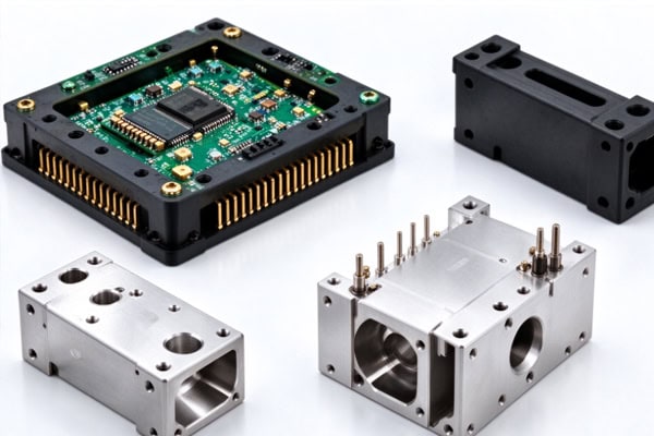
Equipment Housings and Mounting Components
Housings and mounting structures protect internal modules and establish the positioning of electronic assemblies.
- Instrument Housings and Covers: Control external dimensions, mounting-hole positions, and mating surfaces to support proper assembly.
- Mounting Plates and Brackets: Maintain the required hole spacing, support heights, and reference surfaces.
- Probe and Connector Mounts: Position probes and connectors in relation to the components being tested.
Clear dimensional references help reduce alignment errors during installation.
Test Fixtures and Functional Components
Test fixtures hold electronic products in consistent positions during inspection and measurement. Their design should account for locating accuracy, probe access, clamping methods, and repeated use.CNC machining can produce fixture plates, locating blocks, probe guide plates, support bases, and custom positioning components. For electrostatic-sensitive devices, the fixture material and grounding arrangement should also meet the equipment’s protection requirements.A fixture designed around the actual testing process helps maintain repeatable positioning and reliable contact.
Material Selection and Machining Processes
Material choice should reflect mechanical strength, electrical properties, thermal requirements, and the component’s operating environment. Machining methods should then be selected according to its shape and critical features.
Select Materials According to Component Function
Different materials provide different combinations of weight, strength, conductivity, insulation, and machinability.
- Aluminum Alloys: Suitable for many housings, mounting plates, and fixture bodies where low weight and machinability are important.
- Stainless Steel: Appropriate for selected components requiring strength or corrosion resistance.
- Copper Alloys: Can be used for conductive parts and components that transfer heat.
- Engineering Plastics: Suitable for insulating supports, separators, and selected fixture components. Where electrostatic protection is required, choose a material with the specified electrical properties.
Material specifications should be confirmed before production, especially when a component must meet both mechanical and electrical requirements.
Match Machining Methods to Part Geometry
The machining route should prioritize critical dimensions, stable workholding, and access to the required features.
- Milling and Drilling: Produce mounting surfaces, hole patterns, slots, and component pockets.
- Precision Hole Machining: Controls probe-hole diameter, position, and perpendicularity according to the fixture design.
- Turning: Produces cylindrical parts, sleeves, and spacers.
- Finishing and Deburring: Improves the specified surface condition and removes burrs that could affect assembly or probe movement.
For thin-walled parts and components with multiple precision features, the machining sequence should minimize clamping deformation. Appropriate process planning helps maintain dimensional stability.
Precision Control and Quality Inspection
Inspection should focus on the dimensions and surfaces that directly affect assembly, probe contact, and heat transfer. Acceptance criteria should be established before machining begins.
Define Critical Dimensions and Inspection Items
Different components require different inspection priorities. The following table summarizes common checks.
| Component Type | Critical Features | Inspection Focus |
| Equipment Housings | Overall dimensions, mounting holes | Assembly fit |
| Mounting Plates | Hole spacing, reference surfaces | Positioning accuracy |
| Test Fixtures | Locating features, support heights | Repeatable positioning |
| Probe Guide Plates | Hole diameter, hole position, perpendicularity | Probe alignment |
| Heat-Dissipation Components | Contact-surface flatness, surface roughness, fin dimensions | Contact quality and dimensional accuracy |
Calipers and micrometers can measure suitable linear dimensions, while coordinate-measuring or optical equipment may be needed for more complex features. Probe-hole tolerances should match the probe specifications, test-point dimensions, and engineering drawings. Flatness and surface roughness should be checked on heat-transfer contact surfaces when required by the design.
Control Surface Finishing and ESD Requirements
Surface treatments can affect dimensions, corrosion resistance, and electrical contact. These effects should be considered when selecting the finishing process.For ESD-sensitive applications, verify that the material and finished component retain the required electrical properties. Grounding points and electrical contact areas may need special treatment or masking. After finishing, inspect critical dimensions and remove burrs or surface defects that could interfere with assembly.Defining these requirements in advance helps avoid rework and ensures the finished components meet their intended use.
Choosing a CNC Machining Supplier
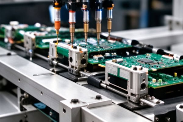
Supplier evaluation should focus on technical capability, inspection arrangements, communication, and delivery requirements.
Confirm Technical Capability and Project Support
When requesting a quotation, provide 2D drawings, 3D models, material specifications, critical tolerances, and estimated quantities. For test fixtures, include probe-hole layouts, locating features, and any ESD-related requirements.For products still under development, confirm whether the supplier can support prototypes, design changes, and small-batch production. Clear technical communication helps identify manufacturing difficulties before production starts.
Confirm Quality and Delivery Requirements
Before placing an order, agree on the specifications and acceptance criteria.
- Confirm material grades and required documentation.
- Identify critical dimensions, surface treatments, and electrical requirements.
- Specify inspection reports or first-article checks when needed.
- Agree on packaging, acceptance procedures, and delivery schedules.
A clear agreement makes quotations easier to compare and helps control production risks.
CNC machining for electronic testing equipment requires the right combination of material selection, dimensional control, surface finishing, and application-specific design. By identifying critical features and inspection requirements before production, equipment manufacturers can reduce assembly adjustments and improve component consistency. TiRapid provides CNC precision machining and custom component manufacturing services for electronic testing equipment, supporting projects from prototype development to small-batch production.
















